 This article is adapted from Section 3 of the User Manual for the Pine Modulated Speed Rotator (MSR).
Related Links: MSR User Manual, MSR Rotator Support Page, Pine Research Instrumentation
Table of Contents
3.1 Site Preparation
The rotator system should be located on a sturdy table or laboratory bench with ample clearance around the perimeter of the rotator enclosure. The front of the rotator should be unobstructed, and there should be at least clearance on each side and behind the rotator, for a total table space of . The location should also include enough space for the control unit and vertical clearance to easily raise and lower the motor unit.
3.2 Unpacking and Setting Up the Rotator
The numbers in parentheses in the installation instructions (below) correspond to the numbering used in the tables and figures found in Section 2 of this manual.
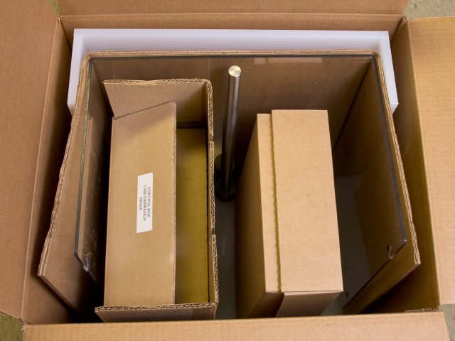
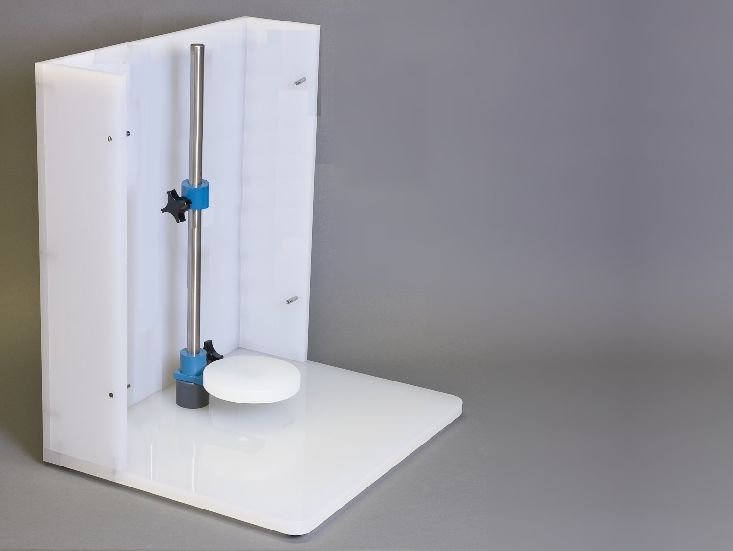
- Inspect the contents of the shipping carton. Remove the top piece of cardboard to reveal the two smaller boxes in the carton. The control unit (10) is packed inside the larger box, and the smaller box holds additional components. Remove both boxes and set aside. Then, carefully remove the enclosure window (7) and the enclosure base (4) from the box. The center post (1) is pre-installed in the enclosure base.
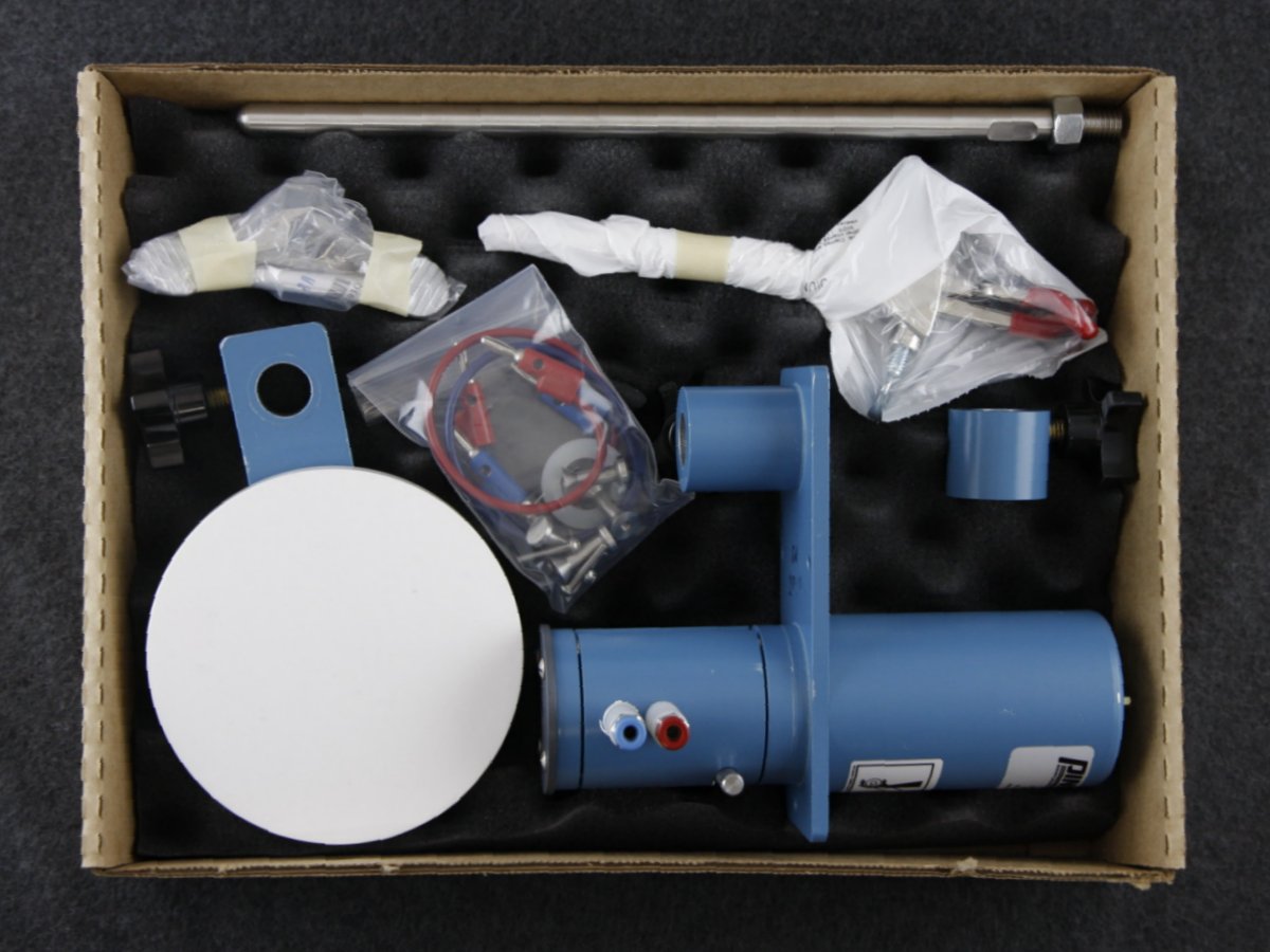
- Open the smaller box. It should contain the motor unit (2), the support collar (5), the cell platform (3), the side post (6), a standard three-pronged laboratory clamp (with right-angle mount), and a small bag containing two banana cables and some additional assembly hardware.
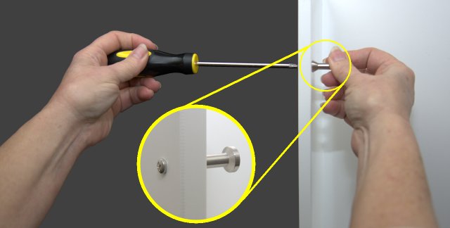
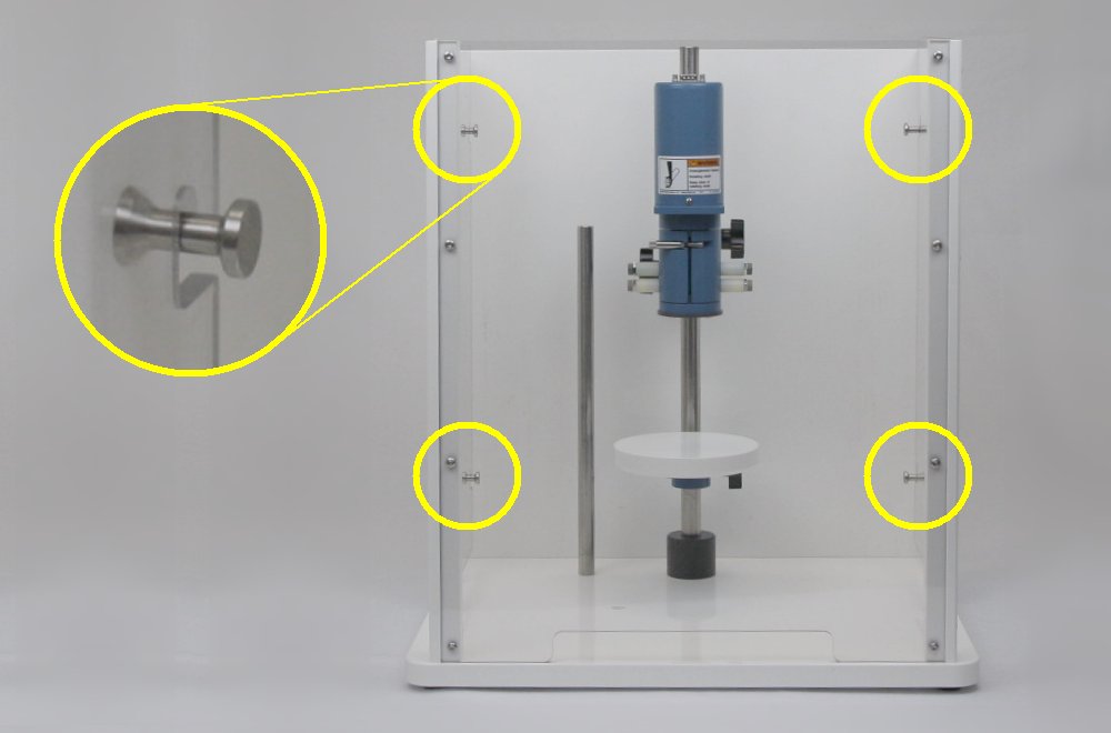
- Locate the small bag of hardware. Remove the four pins and four screws. Place each screw in one of the pre-drilled holes along the side walls of the enclosure, two on the left and two on the right. Install the pins onto the screws. Properly installed pins will point inwards as shown.
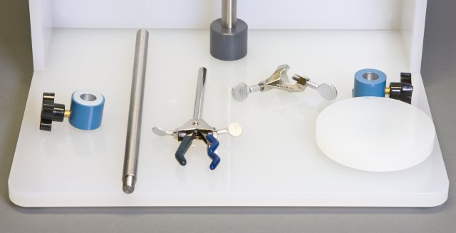
- Locate the support collar (5), side post (6), and three-pronged laboratory clamp (with right-angle mount), cell platform (3), and the large plastic washer (usually shipped in the hardware bag).
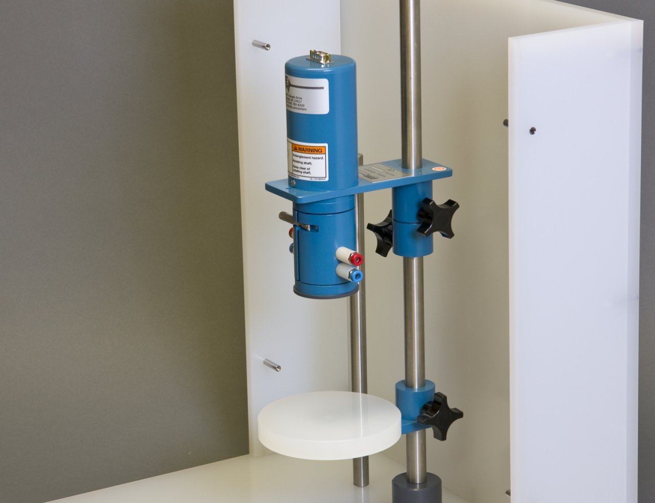
- Slide the cell platform (3) onto the center post and position it near the bottom of the center post (1) with the platform facing up. Tighten the knob to secure the cell platform to the center post. Next, slide the support collar (5) on to the center post and position it slightly above the midpoint of the center post with the knob on the left side. Tighten the knob to secure the support collar to the center post. Slide the plastic washer on the center post and allow it to rest on top of the support collar.
- Carefully slide the motor unit (2) on to the center post (1) until it rests on the support collar (5). Tighten the knob to secure the motor unit to the center post.
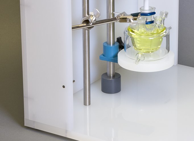
- There are several holes in the floor of the enclosure base (4), which are threaded to accept the side post (6). Choose one of these holes and install the side post in it. Then, mount the laboratory clamp on to the side post.
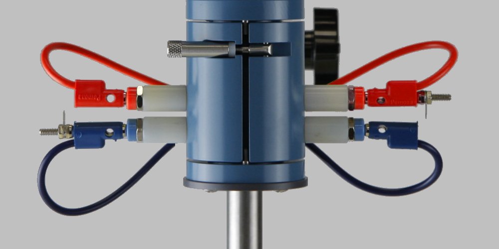
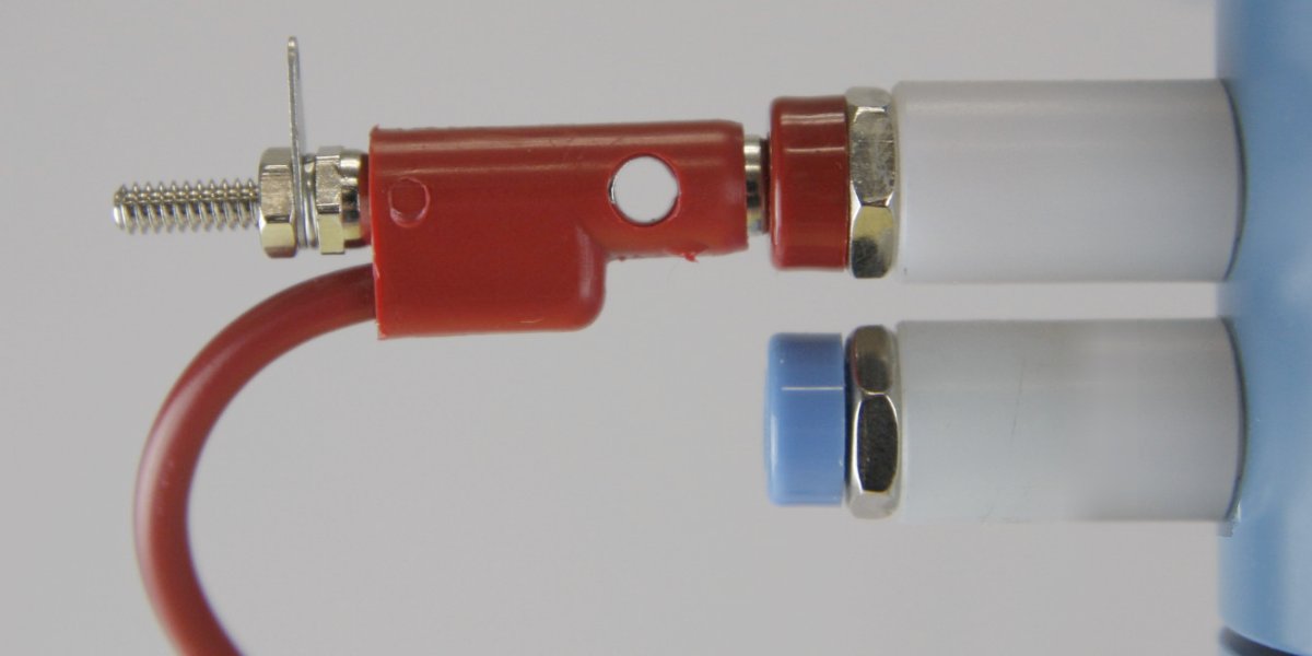
- There are two short banana cables (red and blue) which serve as jumpers between the left and right brush connections. Use the red cable to connect the upper (red) pair of brush connections, and use the blue cable to connect the lower (blue) pair of brush connections, running the wires behind the assembly as shown.
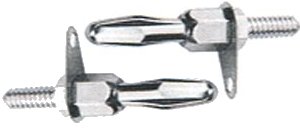
- Insert one banana plug stud into the red banana cable, and insert the other banana plug stud into the blue banana cable. These flat studs are an ideal place to make connections using alligator clips.
The upper (red) jacks make electrical contact with a rotating disk electrode (RDE) or a rotating cylinder electrode (RCE) tip.
When using a rotating ring-disk electrode (RRDE), the upper (red) jacks make contact with the disk, and the lower (blue) jacks make contact with the ring.
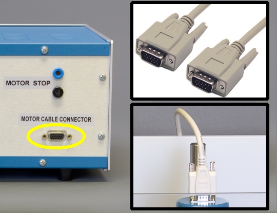
- Remove the control unit (10) from the box and place it next to the enclosure base. Plug the male end of the motor control cable (8) into the motor cable connector on the back of the control unit, and plug the female end of the cable into the top of the motor unit.
- Attach the enclosure by hooking it on to the four pins. The enclosure will rest securely on the enclosure base.
- An appropriate power cord (10 amp rating) is provided with the rotator. Use this cord to connect the control unit to the local power supply.
The local power supply should provide an earth ground connection for the third prong on the power cord.
CAUTION:
The connectors on both ends of the motor control cable MUST be firmly secured by tightening the pair of screws on each connector.
Failure to secure the connectors will result in improper control of the rotation rate.
ATTENTION:
Les connecteurs situés aux deux extrémités du câble de commande du moteur DOIVENT être fermement attachés en serrant les deux vis de chaque connecteur.
Une mauvaise fixation des connecteurs entraînera un mauvais contrôle de la vitesse de rotation.
WARNING:
Failure to connect the third prong of the power cord to a proper earth ground may impair the protection provided by the system.
AVERTISSEMENT:
L’absence de connexion de la troisième broche du cordon d’alimentation à une prise de terre appropriée peut altérer la protection fournie par le système.
CAUTION:
A detachable main power cord is provided with the rotator. Do not replace this cord with an inadequately rated cord.
ATTENTION:
Un cordon d’alimentation amovible est fourni avec le rotateur. Ne remplace pas ce cordon par un cordon de calibre inadéquat.
