 This article is adapted from Section 7 of the User Manual for the Pine Modulated Speed Rotator (MSR).
Related Links: MSR User Manual, MSR Rotator Support Page, Pine Research Instrumentation
7.1 Mechanical Parts and Hardware
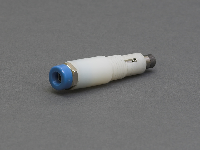
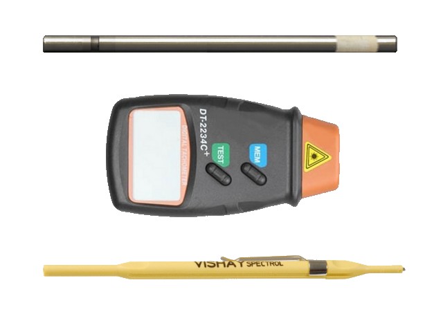
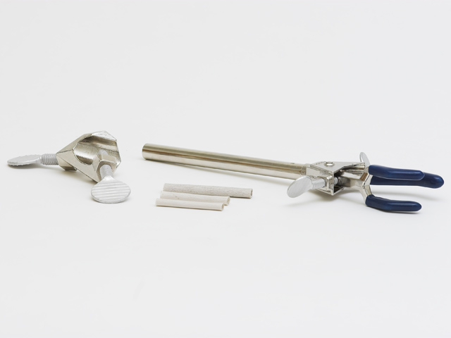
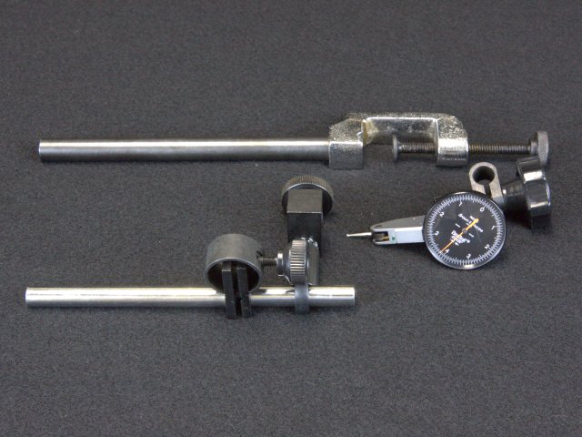
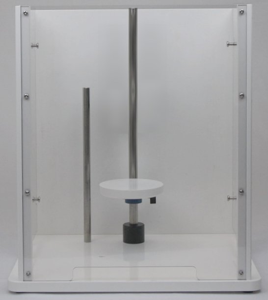
From brush replacement kits to cell platforms and everything in between, many of the spare parts for the MSR Rotator are conveniently located on the same page. All of these parts are subject to normal wear during routine use.
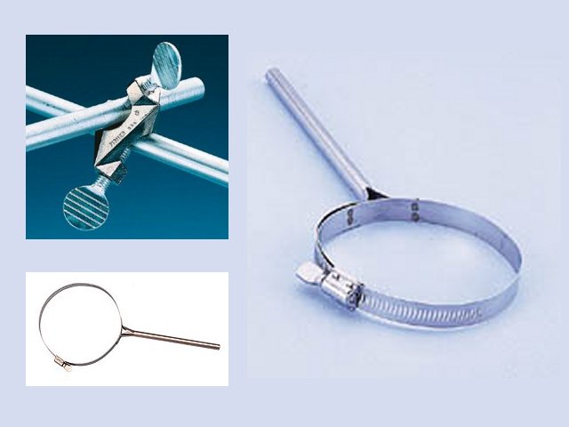
Other normal wear may occur during routine use on the following moving parts (product pages can be accessed by clicking the text):
7.2 Power Cords
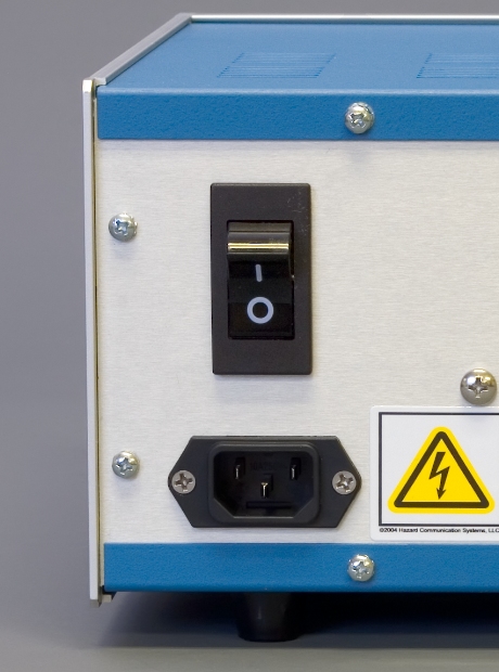
Figure 7.1: Standard C-18 Connection on Power Entry Module
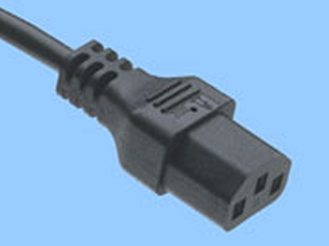
The power entry module on the back panel of the control unit accepts any power cord compatible with a standard C18 plug (see: Figure 7.1). A wide range of power cord options can be accessed via the button below.
7.3 Power Supplies
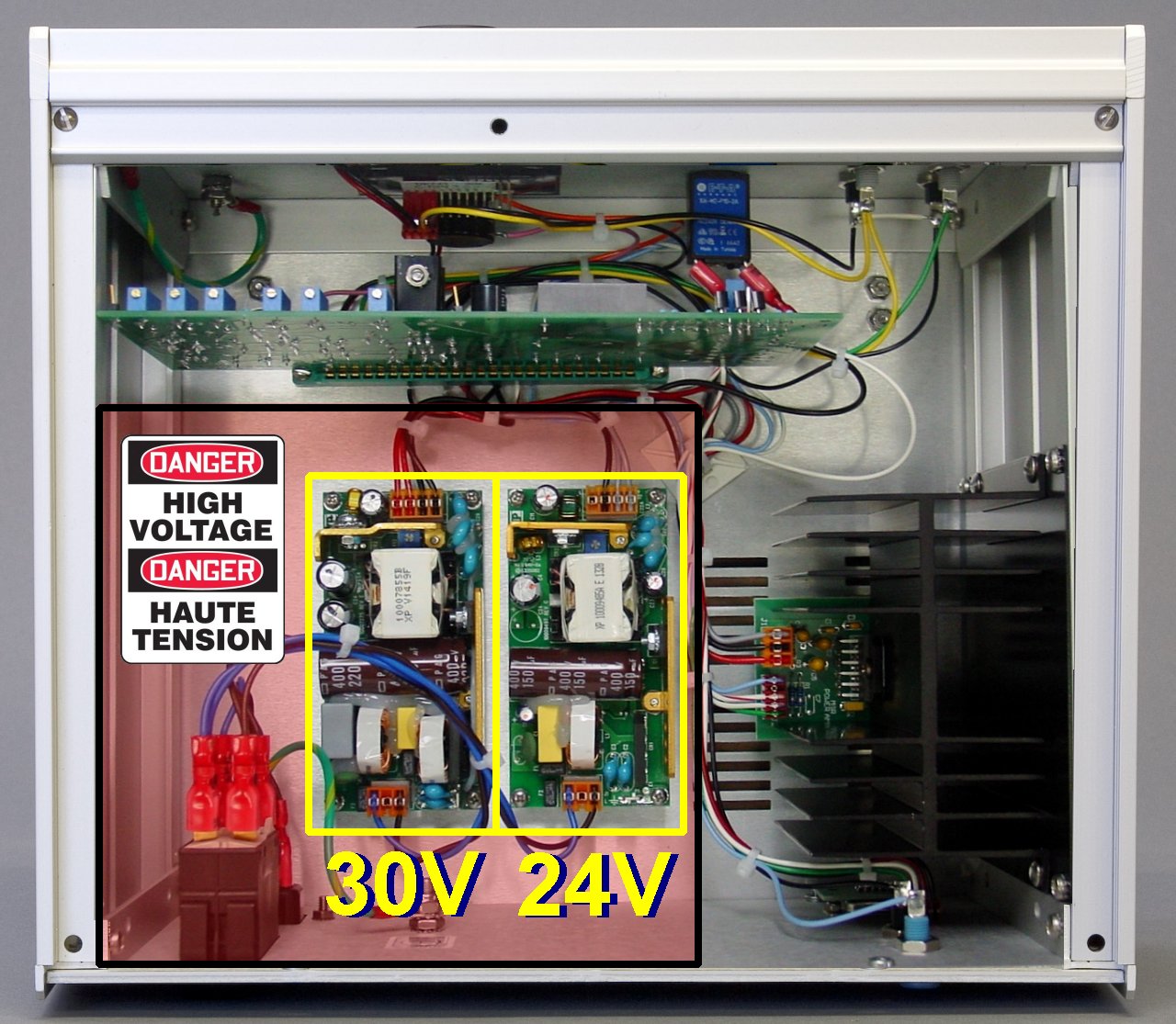
The rotator control unit has two internal power supplies. One of these power supplies is and the other is . These power supplies are located within the high voltage section of the control unit (see: Figure 7.2).
Figure 7.2: Location of High Voltage Power Entry and Internal Power Supplies
WARNING:
Risk of electric shock.
Disconnect power before servicing the control unit.
The shaded region in Figure 7.2 (above) shows the location of the high voltage power entry and the two internal power supplies.
AVERTISSEMENT:
Risque de décharge électrique.
Déconnectez l’alimentation avant de procéder à l’entretien de l’unité de commande.
La région ombragée de la figure 7.2 (ci-dessus) présente l’emplacement de l’entrée de puissance à haute tension et des deux alimentations internes.
In the (rare) event that it is necessary to replace one of the internal power supply units, it is important to carefully identify which type of power supply is to be replaced. First, determine which supply ( or ) is to be replaced (see: Figure 7.2).
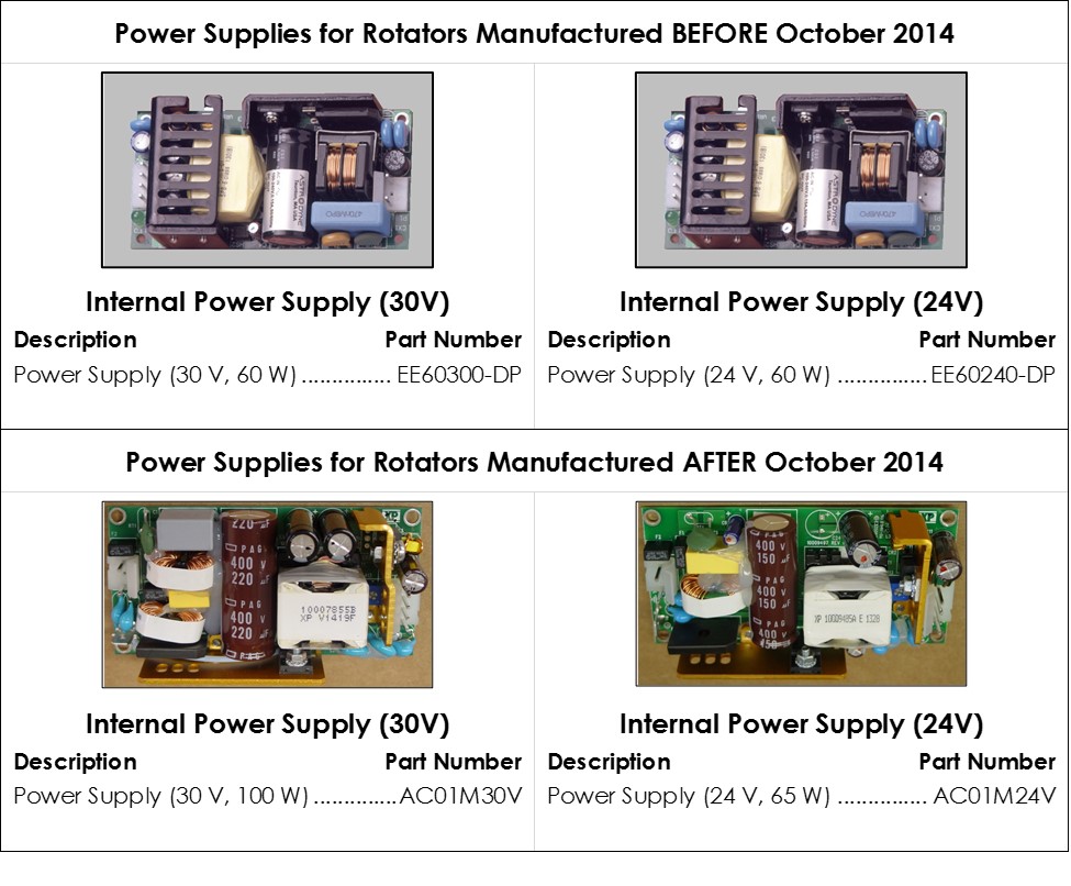
Next, carefully examine the power supply to determine which brand of power supply is to be replaced. Early rotators (prior to October 2014) use power supplies manufactured by Astrodyne, FranMar International or TDK Lambda. Later rotators (after October 2014) use power supplies manufactured by XP Power. Depending upon when the rotator was manufactured, choose the appropriate replacement part shown below.
Figure 7.3: Replacement Internal Power Supplies
WARNING:
Risk of electric shock.
Disconnect all power before servicing the rotator.
AVERTISSEMENT:
Risque de décharge électrique.
Déconnectez toutes les sources d’alimentation avant de procéder à l’entretien du rotateur.
WARNING:
Rotating shaft. Entanglement hazard.
Turn off the power to the rotator and disconnect the power cord from the power source before continuing with this procedure.
AVERTISSEMENT:
Arbre en rotation. Danger d’enchevêtrement.
Éteignez le rotateur et débranchez le cordon d’alimentation de la source d’alimentation avant de poursuivre cette procédure.
