1Background
For neuroelectrochemical measurements, and specifically Fast-Scan Cyclic Voltammetry (FSCV), the current amplifier is typically located physically close to the site where the measurement is made to optimally amplify signal and not noise along the length of the cable going back to the instrument. This current amplifier, called a headstage amplifier, can be of two general types called working-driven or reference-driven.
In a working-driven system, the reference electrode is grounded. The FSCV potential waveform (ramp) is connected to the non-inverting input of the operational amplifier, while the working electrode is connected to the inverting input. In this arrangement, the voltage at the microelectrode will follow the ramp applied to the inverting input.
INFO: With a working-driven headstage amplifier (the Pine Research default), HDCV will show a current response that follows the applied waveform, even when no electrodes are connected (connector just in air) to the headstage amplifier cable. As described later, this is the expected behavior.
In a reference-driven system, the working electrode is virtually grounded. The FSCV potential waveform (ramp) is connected to the inverting input of the operational amplifier, while the working electrode is connected to the non-inverting input. In this arrangement, the voltage at the microelectrode is independent of the ramp applied to the non-inverting input.
Why are there two types of headstage amplifier? Historically, some of the first FSCV reports used a reference-driven headstage system. As such, many of the original core of FSCV users might be more familiar with this type of response. Here are some specific reasons why Pine Research has chosen to offer working-driven headstages, instead:
- For multichannel, working-driven headstage allows each working electrode to have a different waveform. A reference-driven headstage would require that each working electrode have the same waveform.
- Reference-driven virtually grounds the working electrode whereas working driven grounds the reference. Virtual references can float and are more influenced by surrounding grounding (loops), altering results.
- There is some anecdotal evidence that a working driven system is safer to use in-vivo with animals models.
- The resultant signals are the same, once the waveform is subtracted from the signal, so either type of headstage will provide the same response (on the same instrument).
IMPORTANT: Pine Research headstages are working-driven amplfiers. While Pine Research asserts our headstage cables are "universal" for use with several FSCV systems, the user is cautioned to be aware of what style (reference-driven or working-driven) their breakout box/potentiostat expects.
2Working-Driven Headstage
Pine Research currently offers working driven headstage amplifiers. In a working-driven system, the reference electrode is grounded. The FSCV potential waveform (ramp) is connected to the non-inverting input of the operational amplifier, while the working electrode is connected to the inverting input. In this arrangement, the voltage at the microelectrode will follow the ramp applied to the inverting input.
In this two-electrode configuration, current arising from electron-transfer reactions, such as the oxidation of dopamine, passes between reference and working electrodes. The measured current passes through the headstage amplifer, where it is converted to voltage, and sums with the the ramp voltage at the inverting input. Mathematically,
where

is the output voltage,

is input current,

is feedback resistor (gain), and

is the CV ramp voltage. By rearrangement, the signal voltage (proportional to the current across the

feedback resistor in the

headstage) is then
HDCV software, which supports the WaveNeuro FSCV Potentiostat system, performs software subtraction of the ramp according to this relationship, resulting in only the true differential current measurement.
An overly-simplified block diagram shows how the working-driven headstage operates and what is shown in the output (see Figure 1).
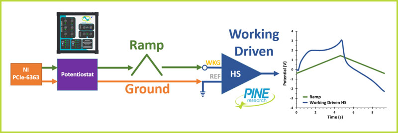
Figure 1. Working-Driven Headstage Block Diagram (General)
As described and predicted by the above mathematical relationships, for the adenosine waveform, the response (blue curve in Figure 1) is actually the current response + ramp waveform (green curve in Figure 1).
In Figure 2, the blue curve was signal+ ramp (working-driven), the gray curve is the CV ramp (waveform) and the dashed black line is the mathematical results of blue - gray curves. The red curve was a redundant check. Pine Research electrical engineering made a custom reference-driven headstage for the WaveNeuro (which results in the data being reversed as the WaveNeuro expects a working driven amplifier). The response of this reference-driven headstage should be equal to the working-driven minus the ramp, which is illustrated by the overlap of the red and dashed black lines. The concluding statement for the data provided in Figure 2 is that despite the functional differences between working-driven and reference-driven amplification for FSCV, the results are the same, despite their appearance on the scope.
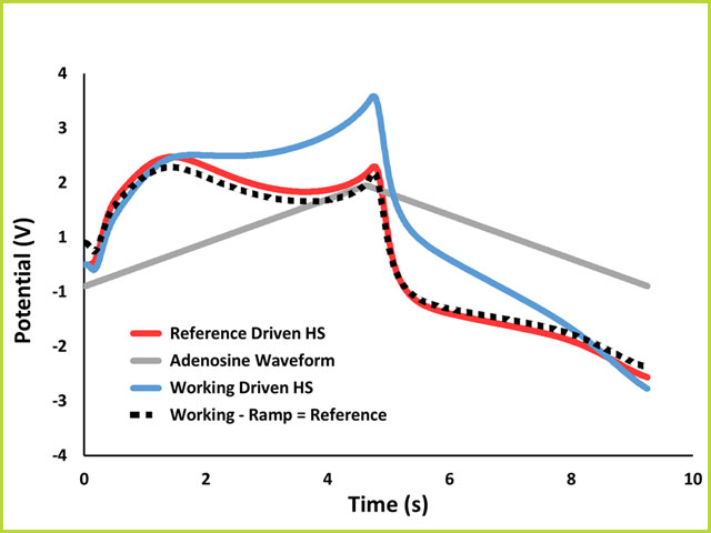
Figure 2. Comparison of Working-Driven and Reference-Driven Headstage Responses on a WaveNeuro FSCV Potentiostat
R.M. Wightman et. al. have reported on this topic in depth.
If, after reviewing this document, you have any questions about our neuroelectrochemical research products, please do not hesitate to contact us.
3Reference-Driven Headstage
In many ways, the reference-driven response is more direct in that the signal observed is the raw signal (not superimposed onto the waveform). Still, as mentioned in Section 1, there are distinct advantages to using a working-driven system, which is why Pine Research has selected working-driven headstage products and designed the WaveNeuro to expect working-driven headstage amplifiers.
One notable difference in the reference-driven headstage is that the response appears to provide a higher degree of morphology, which many FSCV users have used to develop methodologies for specific analytes of interest. Further, some FSCV researchers have developed protocols with regard to the quality of lab-made carbon-fiber microelectrodes and the shape observed on the scope during an FSCV applied waveform. For these reasons, we will describe the reference-driven response here, even though Pine Research does not have any products that support this type of headstage amplifier.
An overly-simplified block diagram shows how the reference-driven headstage operates and what is shown in the output (see Figure 3).
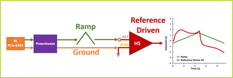
Figure 3. Reference-Driven Headstage Block Diagram (General)
As described and predicted by the above mathematical relationships, for the adenosine waveform, the response (red curve in Figure 3) is simply the raw current signal, which has not been added to the waveform (green curve in Figure 3).
In Figure 4, the blue curve was signal (reference-driven), the gray curve is the CV ramp (waveform) and the dashed black line is the mathematical results of blue + gray curves. The red curve was a redundant check (the working-driven response from Figure 2). As expected, the reference-driven response plus waveform provides the same response as the working-driven headstage response (comparison of red and dotted black curves in Figure 4). The concluding statement for the data provided in Figure 4 is that despite the functional differences between working-driven and reference-driven amplification for FSCV, the results are the same, despite their appearance on the scope.
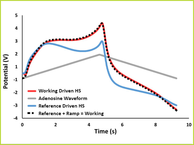
Figure 4. Comparison of Reference-Driven and Working-Driven Headstage Responses on a WaveNeuro FSCV Potentiostat
4Summary
Without a carbon fiber microelectrode in solution or even electrodes attached to the system, an electrochemical signal is observed on the Scope in HDCV. When using Pine Research headstage amplifiers with the WaveNeuro FSCV potentiostat, researchers will make such an observation. The reason for this is primarily because the system uses working-driven headstage amplifiers.
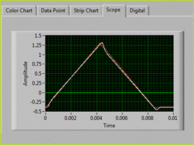
Figure 5. Working-Driven Headstage Response in Air in HDCV on Scope Tab
The measured current (white trace in Figure 5) closely follows the applied waveform (red trace in Figure 5), which is a normal response for the WaveNeuro and is caused by hardware (electronic) configuration, namely, the design choice to offer working-driven headstages. FSCV is typically performed with a two-electrode system, whose electrodes are called working and reference. With a standard Pine Research FSCV setup, the potential waveform is applied to the working electrode and the reference electrode is held at ground, a reference point sometimes referred to as “analog ground." In contrast, other systems (especially early FSCV systems) used reference-driven headstage amplifiers, where the potential waveform is applied to the reference electrode and the working electrode is held at virtual ground. When performing real FSCV experiments, the data are typically displayed as background-subtracted cyclic voltammograms; therefore, the summation of the waveform onto the current response is removed via subtraction and has no bearing on the resultant data. The responses from reference-driven and working-driven systems are equivalent, despite visual differences in their raw data response (prior to background subtraction).
There are several advantages to using working-driven headstage amplifiers. Primarily, the definition of “analog” ground at the reference electrode reduces noise and simplifies the grounding strategy for coupled instruments. Also, the application of the FSCV waveform to the working electrode enables multiple electrodes with different waveforms to be used in one electrochemical cell, at the same time (such as with the WaveNeuro Two
and WaveNeuro Four
).
5References


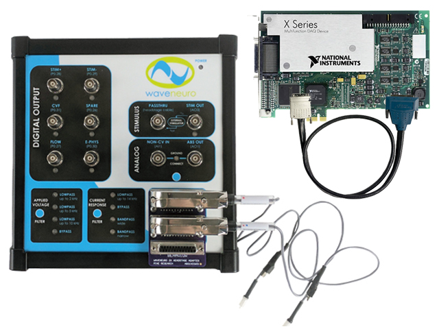 WaveNeuro Two FSCV Potentiostat (Plus Bundle)
and WaveNeuro Four
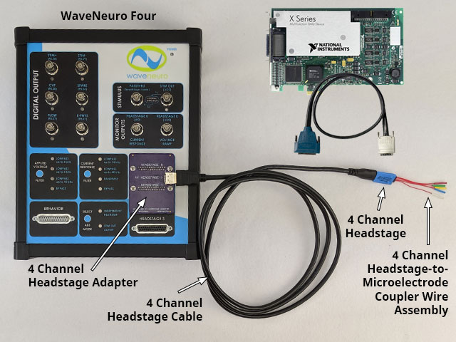 WaveNeuro Four 4-Ch Headstage Kit Plus Bundle
).


