WaveDriver Dummy Cell Descriptions
Last Updated: 5/22/19 by Neil Spinner
1WaveDriver Dummy Cell Descriptions
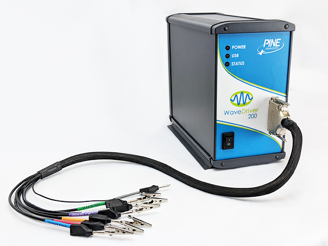
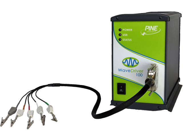
A dummy cell is a network of known resistors, capacitors, and inductors that can be used to test and/or calibrate a potentiostat to ensure that it is working properly. Each Pine Research WaveDriver potentiostat comes with a dummy cell included; however, the exact dummy cell depends on the model of WaveDriver purchased. The EIS Calibration & Dummy Cell (Pine Research part number AFDUM5) is included with the WaveDriver 200 EIS Bipotentiostat/Galvanostat
 WaveDriver 200 EIS Bipotentiostat/Galvanostat
and the WaveDriver 100 EIS Potentiostat/Galvanostat.
 WaveDriver 100 EIS Potentiostat/Galvanostat
The Universal Dummy Cell (Pine Research part number AFDUM3) is included with the WaveDriver 40 DC Bipotentiostat/Galvanostat.
 WaveDriver 40 DC Bipotentiostat/Galvanostat
 WaveDriver 200 EIS Bipotentiostat/Galvanostat
and the WaveDriver 100 EIS Potentiostat/Galvanostat.
 WaveDriver 100 EIS Potentiostat/Galvanostat
The Universal Dummy Cell (Pine Research part number AFDUM3) is included with the WaveDriver 40 DC Bipotentiostat/Galvanostat.
 WaveDriver 40 DC Bipotentiostat/Galvanostat
1.1EIS Calibration & Dummy Cell
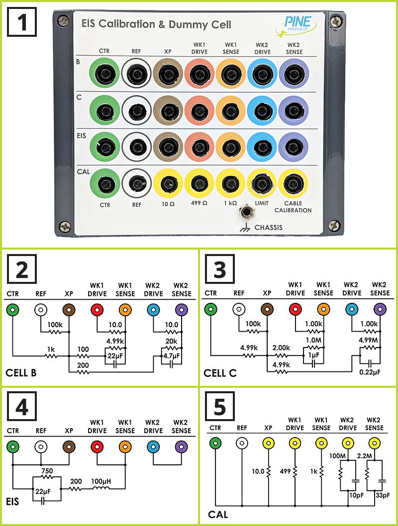
The EIS Calibration & Dummy Cell contains four separate circuit networks (see Figure 1).

| 1 | EIS Calibration & Dummy Cell | Pine Research part number AFDUM5 |
| 2 | Row "B" Circuit Schematic | Used to test DC electrochemical methods |
| 3 | Row "C" Circuit Schematic | Used to test DC electrochemical methods |
| 4 | Row "EIS" Circuit Schematic | Used to test AC electrochemical methods |
| 5 | Row "CAL" Circuit Schematic | Used for various calibration procedures |
Figure 1. EIS Calibration & Dummy Cell (with Schematic Diagrams)
The circuits for rows “B” and “C” of the dummy cell are used for testing the DC capabilities of the WaveDriver. These two rows have the same circuit topology; however, the values of the resistors and capacitors in the two circuits are different.
The circuit for the “EIS” row contains resistors, a capacitor, and an inductor. This circuit provides a predictable EIS response which can be used to verify the AC behavior of the instrument. The results are also useful for learning how to use the EIS circuit fitting feature in the AfterMath software.
The bottom “CAL” row on the dummy cell provides several different loads that can be used to verify the AC behavior of the instrument. The “cable calibration” load is a special circuit which is used to calibrate the cell cable capacitance.
1.2Universal Dummy Cell
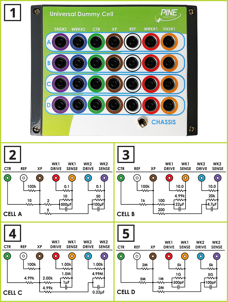
The Universal Dummy Cell contains four separate circuit networks (see Figure 2).

| 1 | Universal Dummy Cell | Pine Research part number AFDUM3 |
| 2 | Row "A" Circuit Schematic | Used to test DC electrochemical methods |
| 3 | Row "B" Circuit Schematic | Used to test DC electrochemical methods |
| 4 | Row "C" Circuit Schematic | Used to test DC electrochemical methods |
| 5 | Row "D" Circuit Schematic | Used to test DC electrochemical methods |
Figure 2. Universal Dummy Cell (with Schematic Diagrams)
The circuit rows of the Universal Dummy Cell are used for testing the DC capabilities of the WaveDriver. All four rows have the same circuit topology; however, the values of the resistors and capacitors in each circuit row are different.


