Legacy Potentiostats
Back to Legacy Potentiostats Back to Legacy Product Support Back to Knowledgebase HomeAFCBP1 Communication Troubleshooting
Last Updated: 4/30/19 by Neil Spinner
1Description
This technical note addresses communication issues that can arise when using the Pine Research AFCBP1 bipotentiostat interfaced to a PC, which controls the bipotentiostat through the AfterMathTM Data Organization Software.
 AfterMath Downloads
There are several layers of software and hardware between AfterMath and the CBP bipotentiostat. Each layer must be functioning properly for AfterMath to communicate correctly and efficiently with the instrument. When troubleshooting communication issues, a systematic approach must be used to diagnose the problem. Refer to this technical note for the suggested approach.
1.1Device Driver Software
The proper device driver software must be installed on the computer. The device driver is from National Instruments and is called “DAQmx”. Older versions of the driver were called “NIDAQ”. These drivers are available as downloads from National Instruments; however, most customers should have the device driver on a DVD that was shipped to them along with the interface board. Pine Research maintains links to the National Instruments download area. An easy way to tell if DAQmx is present on a computer system is to look for a utility program called “MAX” (Measurement and Automation Explorer). This is typically found on the desktop of any computer which has DAQmx installed. If not, it should be located in the START menu under the “National Instruments” folder.
1.2Proper Board Installation
The physical interface board must be installed in the computer in a full-size PCI slot. Sometimes, after a computer has been moved, the interface board may partially slide out of the slot. Always check to assure that the board is secured in the PCI slot and held in place by a screw.
- When installing a new board in a new computer, it is generally best to first install the DAQmx driver, then turn off the computer, then install the interface board, and then turn the computer back on. Doing the steps in this sequence helps to assure that Windows properly recognizes the new board after it is installed
1.3Windows Recognition of Interface Board
Confirm that Windows recognizes and can communicate with the interface board. This is done by using the Device Manager to look at a list of the hardware devices presently installed on the computer. The interface board should appear somewhere in the list. If it doesn’t, then Windows can’t see the board, which means that DAQmx can’t see the board. This means that ultimately AfterMath will not be able to see the board.
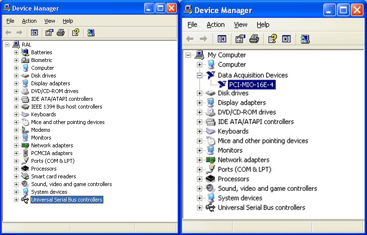
- An example of how the interface board appears in the Device Manager can be seen in Section 1.3.1
- If Windows stubbornly refuses to see the board, it is sometimes necessary to remove the board, restart Windows, shut down Windows, reinstall the board in a (preferably different) PCI slot, and restart Windows
- Windows can sometimes be tricked into “rediscovering” the board by using the “Scan for Hardware Changes” option in the “Actions” menu of the Device Manager
1.3.1Interface Board in Windows Device Manager
The Windows Device Manager allows you to visualize the status of all the various hardware components of your personal computer or laptop. The Device Manager maintains a list of all active hardware devices, sorted by category.
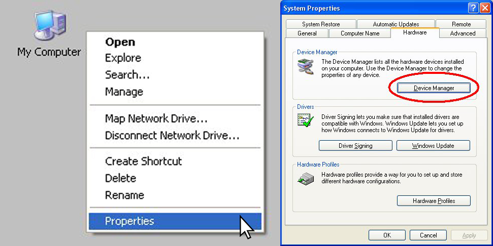
One of the easiest ways to access the Device Manager is to right-click on the “My Computer” icon on the desktop and choose the “Properties” item from the menu. Then, choose the Hardware tab and click on the Device Manager button (see Figure 1).

Figure 1. Device Manager Location
The main view offered by the Device Manager is a list of all of the hardware components installed in your computer. This list is organized into various categories, and each computer will have a unique list depending upon which devices are installed. Examples from two different computers are shown below (see Figure 2).

Figure 2. Device Manager List
1.4DAQmx Communication to Interface Board
Confirm that “DAQmx” can “see” the interface board. This is done by using the MAX utility (Measurement and Automation Explorer). The interface board should appear as one of the attached devices (often under the “Data Neighborhood” or “Legacy Devices” category).
- There are many different versions of the MAX utility. National Instruments provides an overview of what actions can be accomplished using the MAX utility
-
It is possible to use the “Test Panels” feature of the MAX utility to see if the board is “awake” or malfunctioning. Typically, running one of the “Counter” tests is the easiest approach. Just turn on one of the counters (Counter 0 or Counter 1) and a big green indicator on the Test Panel should turn on. This is a pretty good sign that the board is alive and well
1.5AfterMath Communication with AFCBP1
Confirm that AfterMath can “see” the interface board. When AfterMath starts, it senses the presence of the installed board and a “Pine AFCBP1” entry will appear in the lower-left panel of the AfterMath window. AfterMath will attempt to cold start the instrument and establish some initial “idle” conditions.
- If AfterMath can see the AFCBP1, but it is not possible to perform any experiments, then a “permissions file” is probably missing from the AfterMath installation. Permissions files can be obtained by contacting Pine Research directly. Permissions files are usually located in the following folder location:
C:/Program Files (x86)/Pine/AfterMath- If AfterMath appears to be in a continuous loop, repeatedly trying to “cold start” the instrument, then the cable is probably loose (see Section 1.6), or the instrument is not in the proper “External Control” state (see Section 1.7)
1.6Cable Connections
Verify that the interface cable is secure on both ends. It is very common after moving the instrument or the computer for the cable to come loose from one of the two end connectors.
- If the cable is secure, but communications problems persist, remove the cable and examine both ends of the cable for bent pins
- It is rare (but possible) that the interface port cable located inside the potentiostat may be loose. If this is suspected, disconnect the potentiostat from the power source, remove the cover of the potentiostat, and examine the internal ribbon cables which connect from the back panel down to the main analog circuit board
1.7AFCBP1 Control Mode
Verify that the potentiostat is turned on and that the Control Mode is set to “External”.
- The “Control Mode” button is located on the lower-left part of the front panel. It must be pushed and held for about one second to change the control mode to “External”


