1Technique Overview
Cyclic Step Chronoamperometry (CSCA) is a potential step method and is also known as cyclic constant potential bulk electrolysis, cyclic controlled potential amperometry, and cyclic potential pulse electrolysis. In its most simple case, CSCA is the measurement of current vs. time due to a change (step, pulse) in potential that can follow a program of up to four defined steps (forward or reverse) and can further be repeated as desired.
Cyclic Step Chronoamperometry (CSCA) is a widely used method in electrochemistry, due in part to its relative ease of implementation and analysis. CSCA is highly sensitive, as most electrochemical methods are; however, CSCA is poorly selective. In an unstirred cell, in response to a potential step perturbation, electrochemically active species will diffuse to the surface of the working electrode as a function of the potential applied. At the onset of a forward potential step, a large current arising from ion flux to the electrode surface to balance the change in potential gives rise to a capacitive current, which decays rapidly (just like any RC circuit
). The concentration of electrochemically active species near the electrode surface decays with distance from the electrode and the arrival of species to the surface is diffusion limited; therefore, Faradaic current near the electrode surface decays over time as the mass transport limit is reached. The same process, but opposite reaction, arises in the reverse step. These currents provide a typical exponential decay curve, which is described by the Cottrell equation.
CSCA is a unique form of simple chronoamperometry in that users can select up to four distinct steps. These steps can be forward, reverse, or both direction pulses, as defined. Then, the entire sequence (up to four steps) can be repeated as an entire cycle

times. In the case of reactions that are irreversible, one might perform CSCA to understand the qualitative concentration of electroactive species within the diffusional limit of the working electrode as a function of time (cycles).
CSCA is a technique that is often used to elucidate mechanisms related to coupled homogeneous reactions preceding or following an electrode reaction. The simplest coupled homogeneous reactions are Electrochemical-Chemical (EC) and Chemical-Electrochemical (CE) reactions. Bard and Faulkner give a more detailed description of using CSCA to elucidate mechanisms.
2Fundamental Equations
The following is a basic description of the theory behind CSSCA. Please see the literature for a more detailed description of the technique.
Consider the general reaction
with a formal potential

. In general, the potential step applied to the working electrode should be sufficiently more negative than

such that reduction of

to

is complete at the surface of the electrode (
i.e., surface concentration of

at the electrode surface is

). When this occurs, the current is diffusion-limited, much like the current that flows in cyclic voltammetry
after the potential of the electrode sweeps past

.
When the current is diffusion-limited in CA, as stated in the description of chronamperometry,
the time-dependent current transient in a diffusion-limited chronoamperometry experiment is governed by the Cottrell equation
where

is current,

is the number of electrons transferred in the half reaction,

is Faraday's Constant (96,485 C/mol)
,

is the area of the electrode,

is the diffusion coefficient,

is the initial concentration, and

is time. In DPSCA, the time of the transition must be considered. The current transient for the second step, provided it produces diffusion-limited current, is governed by the equation first described by Kambara
where

is the transition time and the other parameters are as above.
3Experimental Setup in AfterMath
To perform a cyclic step chronoamperometry experiment in AfterMath, choose Cyclic Step Chronoamperometry (CSCA) from the Experiments menu (see Figure 1).
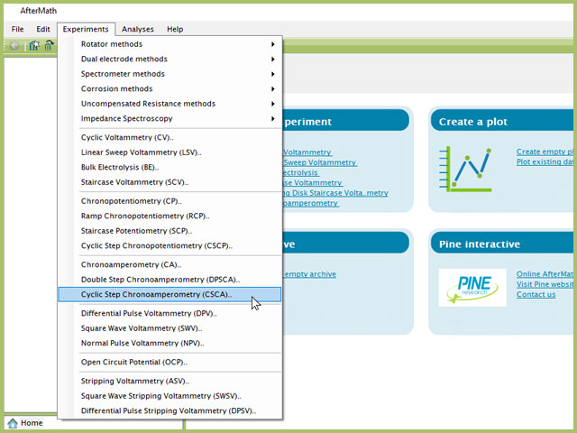
Figure 1. Cyclic Step Chronoamperometry (CSCA) Expeirment Menu Selection in AfterMath
Doing so creates an entry within the archive, called CSCA Parameters. In the right pane of the AfterMath application, several tabs will be shown (see Figure 2).
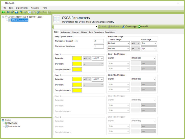
Figure 2. Cylic Step Chronoamperometry (CSCA) Experiment in AfterMath
As with most Aftermath methods, the experiment sequence is
Induction Period → Electrolysis Period (Step 1 → 2 → 3 → 4) → Relaxation Period → Post-Experiment Idle Conditions
Like many experiments, the Induction and Relaxation Periods are on the Advanced Tab. The parameters for a CSCA experiment are fairly simple compared to other methods in AfterMath.
In general, enter minimum required parameters on the Basic tab and press "Perform" to run an experiment. AfterMath will perform a quick audit of the parameters you entered to ensure their validity and appropriateness for the chosen instrument, followed by the initiation of the experiment. In some cases, users may desire to adjust additional settings such as filters, post-experiment conditions, and post-experiment processing before clicking the "Perform" button. Continue reading for detailed information about the fields on each unique tab.
3.1Basic Tab
TIP: Click the AutoFill button ("I Feel Lucky" prior to May 2019) on the top bar in AfterMath to automatically fill all required parameters with reasonable starting values. While the values provided may not be appropriate for your specific system, they are reasonable parameters with which to start your experiment, especially if you are new to the method.
The basic tab contains fields for the fundamental parameters necessary to perform a CSCA experiment. AfterMath shades fields with yellow when a required entry is blank and shades fields pink when the entry is invalid (see Figure 3).
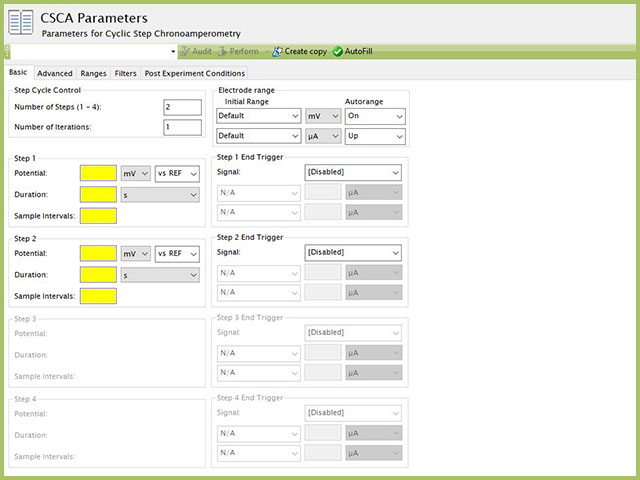
Figure 3. Cyclic Step Chronoamperometry (CSCA) Experiment in AfterMath
During the induction period (whose options are set on the Advanced Tab),
a set of initial conditions are applied to the electrochemical cell and the cell equilibrates at these conditions. Data are not collected during the induction period, nor are they shown on the plot during this period.
After the induction period, the potential applied to the working electrode is stepped to the specified value for the duration of the step, which is called the electrolysis period (on CSCA, the electrolysis periods are found within individual groups, labeled Step 1, Step 2, Step 3, and Step 4).
NOTE: The "Number of Steps" default in AfterMath is 2. Up to four individual steps can be entered, based on the value entered in this initial field. As shown in Figure 3, when 2 steps are selected in the Step Cycle Control group, only Step 1 and Step 2 are available for input, while Step 3 and Step 4 are grayed out. Changing the number of steps to 3 and 4 will enable the corresponding step input fields lower in the form.
The potentiostatic circuit of the instrument maintains constant applied potential relative to the reference electrode while simultaneously measuring the current at the working electrode. During the electrolysis period, potential and current at the working electrode are recorded at regular intervals as specified on the Basic tab for the first potential step (Step 1) followed by each successive step, as indicated by "Number of Steps (1 - 4) in the Step Cycle Control group. There is no pause between the two steps and potential is nearly instantaneously stepped from the one electrolysis potential to the next.
Sampling intervals input box requests a number of data points (intervals) for the given step, spread across the step duration during electrolysis. With duration, a sampling rate can be defined as,
Users should enter a number of intervals that their analysis requires. Commonly, CSCA experiments are sampled at a lower rate (1 sample/s). Not all sampling rates are allowed due to differences in hardware (WaveNow series vs. WaveDriver series, for example).
NOTE: Not all sampling rates are possible. When users enter a number of intervals that is not allowed, AfterMath will prompt the user with an "Interval too short" error. Change the number of intervals and try again. In general, integer values at moderate rates are most often possible.
The Electrode Range group contains the initial current and potential range fields.
These field settings within the Electrode Range group explicitly define the initial current and/or potential ranges used by the potentiostat during the experiment. Additionally, a field for Autorange control for both potential and current appear on this tab. Autorange employs algorithms to adjust the current and potential ranges, as needed, to the most appropriate ranges available to match the measured signal(s). More information on autorange is available elsewhere on the knowledgebase.
Each Step contains the end trigger group, which is unique for each step. By default, the trigger is disabled, as indicated by the [Disabed] selection in the Signal dropdown menu. Each step can end sooner than the defined duration if the trigger limit happens before the step duration has completed. For CSCA, available signals for the trigger are Potential or Current. The most common selection is Current since CSCA is a potentiostatic experiment. In the example below, Step 1 has a current end trigger. The electrolysis will run for 180 s unless the measured current is at or above 250 µA, which will cause the step to stop. If the measured current never reaches 250 µA within 180 s, the entire duration will proceed. More details and examples of using experiment end triggers are found within the knowledgebase.
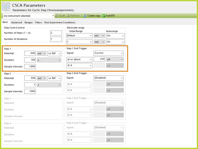
Figure 4. Cyclic Step Chronoamperometry (CSCA) Trigger Setting Example
The experiment concludes with a relaxation period.
During the relaxation period, a set of final conditions (specified on the Advanced tab) are applied to the electrochemical cell and the cell equilibrates at these conditions. Data are not collected during the induction period, nor are they shown on the plot during this period.
A plot of the typical experiment sequence, containing labels of the fields on the Basic tab, helps to illustrate the sequence of events in a CSCA experiment (see Table 1 and Figure 5).
The table below lists the group and field names and symbol for each parameter associated with this experiment (see Table 1).
| Group Name |
Field Name |
Symbol |
| Step Cycle Control |
Number of Steps |
 |
| Step Cycle Control |
Number of Iterations |
 |
| Step n (N = 1, 2, 3, 4) |
Potential |
 |
| Step n (N = 1, 2, 3, 4) |
Duration |
 |
| Step n (N = 1, 2, 3, 4) |
Number of Sample Intervals |
 |
Table 1. Basic Tab Group Names, Field Names, and Symbols.
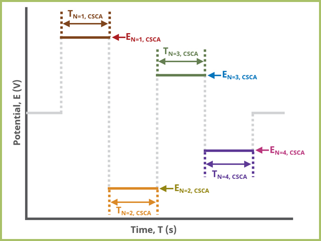
Figure 5. Cyclic Step Chronoamperometry (CSCA) Basic Tab Field diagram
At the end of the relaxation period, the post-experiment idle conditions
are applied to the cell, the post-experiment processing tasks perform, and the instrument returns to the idle state. The default plot generated from the data is current vs. time.
3.2Advanced Tab
The CSCA Advanced tab contains four groups Induction Period, Relaxation Period, Expeirment End Trigger, and iR Compensation (see Figure 6).
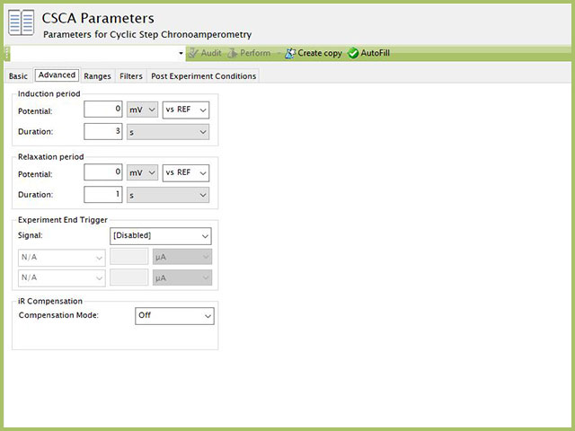
Figure 6. Cyclic Step Chronoamperometry (CSCA) Experiment Advanced Tab
Induction Period is the first step in a CSCA experiment if the Duration is >0 s. During the induction period, the specified potential is applied to the cell for the specified duration. During this period, data are not collected. The Induction Period is believed to "calm" the cell prior to intentional perturbation. More on Induction Period is found within the knowledgebase.
Relaxation Period is the last step in a CSCA experiment if the Duration is >0 s. During the relaxation period, the specified potential is applied to the cell for the specified duration. During this period, data are not collected. The Relaxation Period is believed to "calm" the cell after intentional perturbation. More on Relaxation Period is found within the knowledgebase.
In a CSCA experiment, each step can have a potential or current trigger (Basic Tab). These triggers apply only to the specified step. Additionally, a user may want to apply a trigger across the entire experiment of all steps. Additionally, users may wish to use charge (the integration of current with respect to time, a post-processed data stream) as a trigger, which is not available for each individual step. In this case, the Experiment End Trigger will apply in the same manner as on the Basic Tab, but the trigger here ignores individual steps. If a trigger is set on the Advanced tab, it applies to the overall experiment. This means that if the trigger condition is met during any of the steps, the experiment will (prematurely) end, including all remaining steps that may not yet have begun. Use caution with this trigger to avoid unanticipated termination of CSCA experiments. Details on the End Trigger settings are found elsewhere in the knowledgebase.
Detailed description of the iR Compensation Mode is provided elsewhere on the knowledgebase.
This mode is used to correct for uncompensated resistance in the electrochemical cell.
3.3Ranges, Filters, and Post Experiment Conditions Tab
In nearly all cases, the groups of fields on the Ranges tab are already present on the Basic tab. The Ranges tab shows an Electrode Range group and depending on the experiment shows either, or both, current and potential ranges and the ability to select an autorange function. The fields on this tab are linked to the same fields on the Basic tab (for most experiments). Changing the values on either the Ranges tab or on the Basic tab changes the other set. In other words, the values selected for these fields will always be the same on the Ranges tab and on the Basic tab. More on ranges is found within the knowledgebase,
, as is for autorange.
The Filters tab provides access to potentiostat hardware filters, including stability, excitation, current response, and potential response filters. Pine Research recommends that users contact us
for help in making changes to hardware filters. Advanced users may have an easier time changing the automatic settings on this tab. Filter settings fields are shown for WK1 (working electrode #1) as well as for WK2 (working electrode #2) regardless of the potentiostat connected to AfterMath. More information on filters is available elsewhere on the knowledgebase.
By default, the potentiostat disconnects from the electrochemical cell at the end of an experiment. There are other options available for what these post-experiment conditions can be and are controlled by setting options on the Post Experiment Conditions tab. Complete details on the fields and settings on this Post Experiment Conditions tab are provided elsewhere on the knowledgebase.
4Applications from the Literature
Kwon and Evans
combined cyclic voltammetry, electrochemical quartz crystal microbalance (EQCM) and cyclic step chronoamperometry to characterize electron-beam deposited carbon film electrodes in LiClO4-containing mixed electrolytes. In this research, CSCA was used at four different potentials, starting first with OCP. The duration of each step was 100s, which was done to minimize the effect of viscosity-induced frequency affecting the EQCM measurements. The CSCA results from each step were used to determine the mass change per mole of electrons transferred (MPE) and as expected, results in different values based on each potential step. As compared to cyclic voltammetry, the authors reported that CSCA data were more unambiguous than CV data, resulting in a better estimation of MPE of the carbon film layer and further helped elucidate that the initial film formed during growth of the solid electrolyte interphase (SEI) layer is Li2O.
Li et. al employed CSCA to evaluate charge transport dynamics in a supercapacitor construct.
The results from the CSCA research showed that for the materials in this system, the azomethine nitrogen group (-N=CH-) in polyNi(salphen) with arrangement of the π-conjugated system upon the electron transfer path at intramolecular of the macrocycle instead of the Ni2+/Ni3+ process generate the energy storage capacity by reversible charge transfer. Due to the combining effect of the electrochemical double layer capacitor (EDLC) and pseudocapacitive of the polyNi(salphen) caused by faradaic capacitance, the specific capacitances of the composite electrodes exhibit 60% higher than that of rGO/MWCNTs support electrodes.
Zuo et. al studied the temperature effect of formic acid oxidation at palladium electrodes using CSCA.
In addition to cyclic voltammetry, the researches employed CSCA since, in the cyclic voltammetric study, both the reaction potential and reaction time change simultaneously and it is not easy to disentangle the origins of the CV features. The use of CSCA provided a more direct method of electrochemically interrogating the system.
5References
-
Bard, A. J.; Faulkner, L. A. Electrochemical Methods: Fundamentals and Applications, 2nd ed. Wiley-Interscience: New York, 2000.
-
Cottrell, F. G. Residual current in galvanic polarization regarded as a diffusiona problem. Z. Phys. Chem., 1903, 42, 385–431.
-
Tomihito, K. Polarographic Diffusion Current Observed with Square Wave Voltage. I. Effect Produced by the Sudden Change of Electrode Potential. Bull. Chem. Soc. Jpn., 1954, 27(8), 523-526.
-
Kwon, K.; Evans, J. W. Comparison between cyclic voltammetry and chronoamperometry when coupled with EQCM for the study of the SEI on a carbon film electrode. Electrochim. Acta, 2003, 49(6), 867-872.
-
Li, X.; Deng, F.; Li, J.; Li, Z.; Kang, F. Fast and reversible redox reaction of polyNi(salphen)@reduced graphene oxide/multiwall carbon nanotubes composite for supercapacitors. Electrochim. Acta, 2018, 284, 355-365.
-
Uwitonze, N.; Zhou, D.; Lei, J.; Chen, W.; Zuo, X. Q.; Cai, J.; Chen, Y-X. The high Tafel slope and small potential dependence of activation energy for formic acid oxidation on a Pd electrode. Electrochim. Acta, 2018, 283, 1213-1222.


