


Instrument User Guides
Back to Instrument User Guides Back to Applications Back to Knowledgebase HomeWaveDriver 40 Bipotentiostat/Galvanostat User Guide
Last Updated: 1/6/22 by Alex Peroff
Download as PDF1Preface
1.1Scope
This user guide describes the WaveDriver 40 Bipotentiostat/Galvanostat system.
 WaveDriver 40 DC Bipotentiostat/Galvanostat
The target audience for this user guide is a professional scientist or engineer (or student of science and engineering) with a basic knowledge of scientific measurement, data presentation, and electrochemistry. Practical aspects of making electrochemical measurements using the WaveDriver 40 instrument are discussed.
WaveDriver 40 DC Bipotentiostat/Galvanostat
The target audience for this user guide is a professional scientist or engineer (or student of science and engineering) with a basic knowledge of scientific measurement, data presentation, and electrochemistry. Practical aspects of making electrochemical measurements using the WaveDriver 40 instrument are discussed.A small portion of this guide is dedicated to the subject of using the AfterMath software package
 AfterMath Downloads
to control the WaveDriver 40 instrument. This information about AfterMath is limited primarily to the subject of installing the software, connecting to the instrument, and verifying that the system works correctly. More extensive descriptions of how to use AfterMath software may be found in the Software category of the Pine Research Knowledgebase.
Software
AfterMath Downloads
AfterMath User Guide
AfterMath Downloads
AfterMath User Guide
1.2Copyright
This publication may not be reproduced or transmitted in any form, electronic or mechanical, including photocopying, recording, storing in an information retrieval system, or translating, in whole or in part, without the prior written consent of Pine Research Instrumentation, Inc.
1.3Trademarks
All trademarks are the property of their respective owners. Windows is a registered trademark of Microsoft Corporation (Redmond, WA). WaveDriver®, WaveVortex® and AfterMath® are registered trademarks of Pine Research Instrumentation, Inc. (Durham, NC).
1.4Use Limitation
The WaveDriver 40 instrument is not designed for use in experiments involving human subjects and/or the use of electrodes inside or on the surface of the human body.
Any use of this instrument other than for its intended purpose is prohibited.
1.5Harmful or Corrosive Substances
The operator of the WaveDriver 40 should have prior experience working in a chemical laboratory and knowledge of the safety issues associated with working in chemical laboratory. Electrochemical experiments may involve the use of harmful or corrosive substances, and the operator should wear personal protective equipment while working with these substances. At a minimum, the operator should wear the following items to avoid contact with harmful or corrosive substances:
- Eye protection (safety goggles, face shield, etc.)
- Laboratory coat (flame resistant and solvent resistant)
- Solvent-resistant gloves
- Closed-toe shoes
Additional personal protective clothing and equipment may be required depending upon the nature of the chemicals used in an experiment. A complete discussion of chemical laboratory safety practices is beyond the scope of this user guide, and the reader is directed to a chemical safety bibliography for additional information.
 American Chemical Society Committee on Chemical Safety Hazards Identification and Evaluation Task Force Identifying and Evaluating Hazards in Research Laboratories: Guidelines Developed by the Hazards Identification and Evaluation Task Force of the ACS Committee on Chemical Safety American Chemical Society, 2015.
Council, N. R. Prudent Practices in the Laboratory: Handling and Management of Chemical Hazards, Updated Version, 2011.
American, C. S. C. o. C. S. Safety in Academic Chemistry Laboratories, 7 ed. American Chemical Society: State College, PA, 2003.
Council, N. R. Prudent Practices in the Laboratory: Handling and Management of Chemical Hazards, Updated Version, 2011.
American, C. S. C. o. C. S. Safety in Academic Chemistry Laboratories, 7 ed. American Chemical Society: State College, PA, 2003.
L’opérateur du WaveDriver 40 doit avoir une expérience préalable de travail dans un laboratoire de chimie et la connaissance des mesures de sécurité associées aux travaux dans un laboratoire de chimie. Les expériences en électrochimie peuvent impliquer l'utilisation de substances nocives ou corrosives, et l'opérateur doit porter des équipements de protection individuelle lorsqu'il travaille avec ces substances. Au minimum, l'opérateur doit porter les articles suivants pour éviter le contact avec les substances nocives ou corrosives:
- Protection des yeux (lunettes de sécurité, masque de protection facial, ect.)
- Blouse de laboratoire (résistante au feu et résistante aux solvants)
- Gants de protection résistants aux solvants
- Chaussures fermées
Des vêtements et équipements de protection individuelle supplémentaires peuvent être requis en fonction de la nature des produits chimiques utilisés dans une expérience. Une discussion complète des pratiques de sécurité de laboratoire chimique est au-delà de la portée de ce guide de l'utilisateur, et le lecteur est dirigé vers une bibliographie de sécurité chimique pour des informations supplémentaires.
American Chemical Society Committee on Chemical Safety Hazards Identification and Evaluation Task Force Identifying and Evaluating Hazards in Research Laboratories: Guidelines Developed by the Hazards Identification and Evaluation Task Force of the ACS Committee on Chemical Safety American Chemical Society, 2015.
Council, N. R. Prudent Practices in the Laboratory: Handling and Management of Chemical Hazards, Updated Version, 2011.
American, C. S. C. o. C. S. Safety in Academic Chemistry Laboratories, 7 ed. American Chemical Society: State College, PA, 2003.
Council, N. R. Prudent Practices in the Laboratory: Handling and Management of Chemical Hazards, Updated Version, 2011.
American, C. S. C. o. C. S. Safety in Academic Chemistry Laboratories, 7 ed. American Chemical Society: State College, PA, 2003.
1.6Service and Warranty Information
For questions about proper operation of the WaveDriver 40 system or other technical issues, please contact Pine Research directly.
 Contact
If the WaveDriver 40 system or one of its components or accessories must be returned to the factory for service, please contact Technical Service (see above) to obtain a Return Material Authorization (RMA) form. Include a copy of this RMA form in each shipping carton and ship the cartons to the Factory Return Service Address (below).
| FACTORY RETURN SERVICE ADDRESS |
| Pine Instrument Company ATTN: RMA # <RMA number> 104 Industrial Drive Grove City, PA 16127, USA |
| LIMITED WARRANTY |
| The WaveDriver 40 Bipotentiostat/Galvanostat instrument (hereafter referred to as the “INSTRUMENT”) offered by Pine Research Instrumentation (hereafter referred to as “PINE”) is warranted to be free from defects in material and workmanship for a one (1) year period from the date of shipment to the original purchaser (hereafter referred to as the “CUSTOMER”) and used under normal conditions. The obligation under this warranty is limited to replacing or repairing parts which shall upon examination by PINE personnel disclose to PINE's satisfaction to have been defective. The customer may be obligated to assist PINE personnel in servicing the INSTRUMENT. PINE will provide telephone support to guide the CUSTOMER to diagnose and effect any needed repairs. In the event that telephone support is unsuccessful in resolving the defect, PINE may recommend that the INSTRUMENT be returned to PINE for repair. This warranty being expressly in lieu of all other warranties, expressed or implied and all other liabilities. All specifications are subject to change without notice. |
| The CUSTOMER is responsible for charges associated with non-warranted repairs. This obligation includes but is not limited to travel expenses, labor, parts and freight charges. |
1.7Instrument Markings
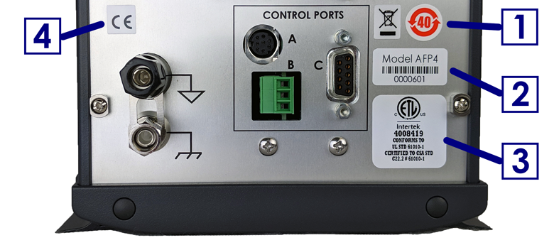
Labels located on the back panel of each individual WaveDriver 40 include information about the make, model, and serial number of the instrument. These labels also indicate any certifications or independent testing agency marks which pertain to the instrument (see Figure 1).
 |
||
| 1 | Environmental Labels | These labels indicate that the instrument has an Environment Friendly Use Period (EFUP) of forty years and that the instrument should be treated as recyclable electronic equipment at the end of its useful life. |
| 2 | Serial Number Label | This label indicates the model and serial number of the instrument and includes a machine-readable bar code. |
| 3 | NRTL Mark |
WaveDriver systems which bear the ETL/Intertek mark are listed by Intertek to UL 61010-1 (issued 11-MAY-2012; Ed. 3), CSA C22.2 #61010-1 (issued 11-MAY-2012; Ed. 3), and IEC 61010-1 (issued 10-JUN-2010; Corrigendum 1: 11-MAY-2011). Intertek is a Nationally Recognized Testing Laboratory (NRTL) recognized by the United States Occupational Safety and Health Administration (OSHA). |
| 4 | European CE Mark |
WaveDriver systems which comply with one or more EU directives bear the CE mark. See the "CE Declaration of Conformity" attached to the end of this user guide for more details. |
Figure 1. WaveDriver 40 Instrument Markings
1.7.1Serial Number
For purposes of uniquely identifying a particular instrument, there is a label on the back panel of each WaveDriver 40 instrument that indicates the model number and the serial number. The serial number is also encoded with a machine-readable barcode on the same label (see Figure 1).
1.7.2Model Numbers
The relationship between the model name and model number for the WaveDriver 40 system is described below (see Table 1). The model number has the format “AFPNXY” where N is a single numeric digit, and X and Y are either blank or uppercase alphabetic characters. Pine Research part numbers for various components of the system (such as power cords, cell cables, and accessories) are described in more detail later (see Section 5 and Section 7).
| Model Number: | A | F | P | N | X | Y | Model Name: |
| A | F | P | 4 | WaveDriver 40 | |||
| A | F | P | 3 | WaveDriver 200 | |||
| A | F | P | 5 | WaveDriver 100 |
Table 1. WaveDriver Instrument Model Numbers and Model Names
The WaveDriver 200
 WaveDriver 200 EIS Bipotentiostat/Galvanostat
is similar to the WaveDriver 40, but it may also be used to perform Electrochemical Impedance Spectroscopy (EIS) methods. The WaveDriver 100
WaveDriver 200 EIS Bipotentiostat/Galvanostat
is similar to the WaveDriver 40, but it may also be used to perform Electrochemical Impedance Spectroscopy (EIS) methods. The WaveDriver 100
 WaveDriver 100 EIS Potentiostat/Galvanostat
is a potentiostat/galvanostat (meaning it has only one working electrode channel, unlike the WaveDriver 40 which is a bipotentiostat and has two), and it may also be used to perform EIS methods.
WaveDriver 100 EIS Potentiostat/Galvanostat
is a potentiostat/galvanostat (meaning it has only one working electrode channel, unlike the WaveDriver 40 which is a bipotentiostat and has two), and it may also be used to perform EIS methods.
WaveDriver 200 EIS Bipotentiostat/Galvanostat
is similar to the WaveDriver 40, but it may also be used to perform Electrochemical Impedance Spectroscopy (EIS) methods. The WaveDriver 100
WaveDriver 100 EIS Potentiostat/Galvanostat
is a potentiostat/galvanostat (meaning it has only one working electrode channel, unlike the WaveDriver 40 which is a bipotentiostat and has two), and it may also be used to perform EIS methods. 1.8Icons (Icônes)
Special icons are used to call attention to safety warnings and other useful information found in this document (see Table 2, Table 3, and Table 4).
Des icônes spéciales (voir Tableau 2, Tableau 3, et Tableau 4) sont utilisées pour attirer l’attention sur des avertissements de sécurité et d’autres renseignements utiles disponibles dans ce document.
| Icon | Meaning |
|
|
STOP: For a procedure involving user action or activity, this icon indicates a point in the procedure where the user must stop the procedure. |
| ARRÊT: Dans une opération impliquant l’action ou l’activité d’un utilisateur, cette icône indique l’étape où l’utilisateur doit arrêter l’opération. | |
|
|
NOTE: Important or supplemental information. |
| REMARQUE: Renseignements importants ou complémentaires. | |
|
|
TIP: Useful hint or advice. |
| CONSEIL: Astuce ou conseil utile. |
Table 2. Special Icons used in this Document
(Tableau 2. Icônes spéciales utilisées dans ce document)
(Tableau 2. Icônes spéciales utilisées dans ce document)
| Icon | Meaning |
|
|
WARNING: Indicates information needed to prevent injury or death to a person or to prevent damage to equipment. |
| AVERTISSEMENT: Indique les informations nécessaires pour prévenir les blessures ou le décès d'une personne ou pour éviter d'endommager l'équipement. | |
|
|
ROTATING SHAFT HAZARD: Indicates information needed to prevent injury or death to a person due to a high-speed rotating shaft. |
| DANGER LIÉ À LA ROTATION DE L’ARBRE: Indique les informations nécessaires pour prévenir les blessures ou le décès d'une personne à cause de la vitesse élevée de rotation de l’arbre. | |
|
|
RISK OF ELECTRICAL SHOCK: Indicates information needed to prevent injury or death to a person due to electrical shock. |
| RISQUE DE DÉCHARGE ÉLECTRIQUE: Indique les informations nécessaires pour prévenir les blessures ou le décès d'une personne à cause d’une décharge électrique. |
Table 3. Safety Warning Icons used in this Document
(Tableau 3. Icônes d'avertissement de sécurité utilisées dans ce document)
(Tableau 3. Icônes d'avertissement de sécurité utilisées dans ce document)
| Icon | Meaning |
|
|
CAUTION: Indicates information needed to prevent damage to equipment. |
| ATTENTION: Indique les informations nécessaires pour éviter d'endommager l'équipement. | |
|
|
RISK OF ELECTROSTATIC DAMAGE: Indicates information needed to prevent damage to equipment due to electrostatic discharge. |
| RISQUE DE DOMMAGES ÉLECTROSTATIQUES: Indique les informations nécessaires pour éviter d'endommager l'équipement à cause d’une décharge électrostatique. | |
|
|
TEMPERATURE CONSTRAINT: Indicates when an operation or use of equipment is limited to a specified temperature range. |
| CONTRAINTES DE TEMPÉRATURE: Indique lorsqu’une opération ou un usage de matériel est limité à une plage de températures spécifique. |
Table 4. Other Safety Warning Icons used in this Document
(Tableau 4. Autres Icônes d'avertissement de sécurité utilisées dans ce document)
(Tableau 4. Autres Icônes d'avertissement de sécurité utilisées dans ce document)
1.9Safety Labels (Étiquettes de sécurité)
Specific safety warnings are found on labels attached to the instrument (see Figure 2).
Les avertissements de sécurité spécifiques suivants se trouvent sur les étiquettes apposées sur l'instrument (voir Figure 2).
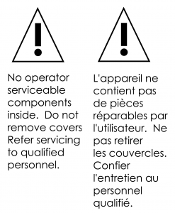
Figure 2. Safety Warning Labels on Back Panel of Instrument
1.10General Safety Warnings (Avertissements de sécurité généraux)
The following safety warnings pertain to general use of the instrument. More specific safety warnings are found in later sections of this document which pertain to particular operations and procedures involving the instrument.
Des avertissements de sécurité plus spécifiques se trouvent dans les sections suivantes de ce document, concernant les opérations et les procédures particulières relatives à l'instrument.
1.11Electrostatic Discharge Information
Electrostatic discharge (ESD) is the rapid discharge of static electricity to ground. An ESD event occurs when two bodies of different potential approach each other closely enough such that static charge rapidly passes from one object to the next. Sensitive electronics in the path of the discharge may suffer damage. Damaging ESD events most often arise between a statically charged human body and a sensitive electronic circuit. The human body can easily accumulate static charge from simple movement from one place to another (i.e., walking across a laboratory).
Potentiostat users must always be aware of the possibility of an ESD event and should employ good practices to minimize the chance of damaging the instrument. Some examples of good ESD prevention practices include the following:
- Self-ground your body before touching sensitive electronics or the electrodes. Self-grounding may be done by touching a grounded metal surface such as a metal pipe.
- Wear a conductive wrist-strap connected to a good earth ground to prevent a charge from building up on your body.
- Wear a conductive foot/heel strap or conductive footwear in conjunction with standing on a grounded conductive floor mat.
- Increase the relative humidity in the air to minimize static generation.
The WaveDriver 40 has been tested and found to be compliant with the European EMC product specific Standard EN 61326-1:2013 for immunity and emissions. The immunity standard includes testing for ESD to IEC 61000-4-2:2008.
1.12Hazardous Material Information
Disclosure tables in both English and Mandarin are provided (see Table 5 and Table 6) which detail information pertaining to the list of hazardous substances classified under the Restriction of Hazardous Substances Directive (RoHS).
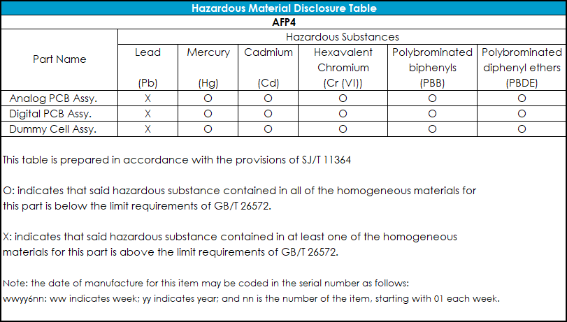
Table 5. WaveDriver 40 Hazardous Materials Disclosure (English)
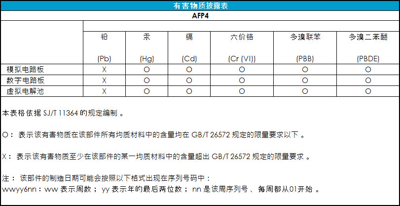
Table 6. WaveDriver 40 Hazardous Materials Disclosure (Mandarin)
1.13Software License
Purchase of a WaveDriver 40 instrument includes a license to use the AfterMath software package
AfterMath Downloads
to control the instrument and analyze data collected using the instrument. Pine Research understands that the WaveDriver 40 is used in a laboratory environment where multiple computers are present and where data acquired using one computer might be analyzed using a different computer. The software license describes how AfterMath may be used with the WaveDriver 40 in a laboratory with multiple computers. You can find the AfterMath software license here.
AfterMath Software License
2Product Specifications
2.1Instrument Description
The WaveDriver 40
WaveDriver 40 DC Bipotentiostat/Galvanostat
is a benchtop instrument that is controlled by a personal computer (via a USB cable) using the AfterMath software package
AfterMath Downloads
developed by Pine Research. The WaveDriver 40 may be operated as a potentiostat, a galvanostat, or as a bipotentiostat. The instrument is most often used to control the potential (or current) at one or two working electrodes located in an electrochemical cell along with a counter electrode and a suitable reference electrode. Popular DC electrochemical test methods (such as Cyclic Voltammetry,
Cyclic Voltammetry (CV)
Chronoamperometry,
Chronoamperometry (CA)
, Pulse and Square Wave Voltammetry,
Normal Pulse Voltammetry (NPV)
Square Wave Voltammetry (SWV) etc.) may be performed using the WaveDriver 40.
WaveDriver 40 DC Bipotentiostat/Galvanostat
is a benchtop instrument that is controlled by a personal computer (via a USB cable) using the AfterMath software package
Square Wave Voltammetry (SWV) etc.) may be performed using the WaveDriver 40.
The working electrodes feature three potential ranges (±2.5 V, ±10.0 V and ±15.0 V) and eight current ranges (from ±1.0 A down to ±100.0 nA), making the WaveDriver 40 suitable for use with a wide variety of electrochemical cells. Because the WaveDriver 40 can control two independent working electrodes (i.e., it can operate as a two-channel potentiostat or bipotentiostat), the instrument may be used with dual electrode configurations such as the rotating ring-disk electrode (RRDE).
2.2Software Description
The AfterMath scientific data analysis and instrument control software developed by Pine Research is included with each WaveDriver 40 instrument.
AfterMath Downloads
AfterMath offers several important benefits:
- Instrument Control. When started, AfterMath automatically detects all compatible instrumentation attached to the computer and provides complete control over each instrument. AfterMath can simultaneously control multiple instruments, and multiple experiments may be queued on each individual instrument. Even as new experiments are queued or running in the background, data acquired in previous experiments may be manipulated by the user.
- Flexible Plotting. AfterMath has a powerful "drag-n-drop" feature that allows traces from one plot to be quickly and easily copied and moved to other plots. Preparing an overlay plot from several voltammograms is straightforward. AfterMath provides precise control over line sizes, point markers, colors, axis limits, axis labels, and tick marks. One or more text boxes may be placed anywhere on a plot, and the text may be formatted with any combination of fonts, font sizes, or colors as desired.
- Scientific Units. Unlike graphing software designed for business and marketing applications, AfterMath is designed with scientific data in mind. Proper management of scientific units, metric prefixes, scientific notation, and significant figures are built into AfterMath. For example, if an operation divides a potential measured in millivolts by a current measured in nanoamperes, then AfterMath properly provides the result as a resistance measured in megaohms.
- Data Archiving. A unique and open XML-based file format allows data from several related experiments to be stored together in one single archive file. Keeping related experiments together in an archive file eliminates the need to manage multiple individual data files on the hard drive. The internal archive hierarchy can contain as many subfolders, reports, plots, notes, experimental parameters, and data sets as desired.
- Tools and Transforms. Flexible tools can be placed on any graph to precisely measure quantities like peak height and peak area. Multiple tools can be placed on a plot, and all such tools remain exactly where they are placed, even if the data archive is saved to a disk and reloaded at a later time. Fundamental mathematical operations (addition, multiplication, integration, logarithm, etc.) can be applied to any trace on any plot.
2.3Instrument Specifications
The WaveDriver 40 instrument offers the following electrode control modes: potentiostatic (POT), galvanostatic (GAL), open circuit potential (OCP), and zero resistance ammeter (ZRA). Uncompensated resistance (Ru) measurement and compensation is available via current interrupt and positive feedback techniques.
2.3.1WaveDriver 40 Bipotentiostat/Galvanostat Specifications
All product specifications for the WaveDriver 40 can be found at the link provided here:
Product Specifications
2.4Standard Electrochemical Methods
The WaveDriver 40 bipotentiostat together with the AfterMath software package
AfterMath Downloads
can perform many electrochemical techniques. Further descriptions about how to configure and execute these techniques can be found in AfterMath software documentation.
Methods and Techniques
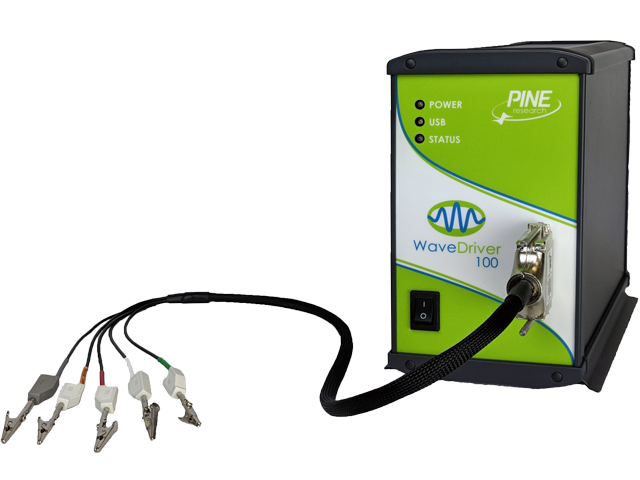
2.5System Components
The WaveDriver 40 bipotentiostat system, as shipped from the production facility, includes all parts, cables, and software necessary for its initial use (see Table 7).
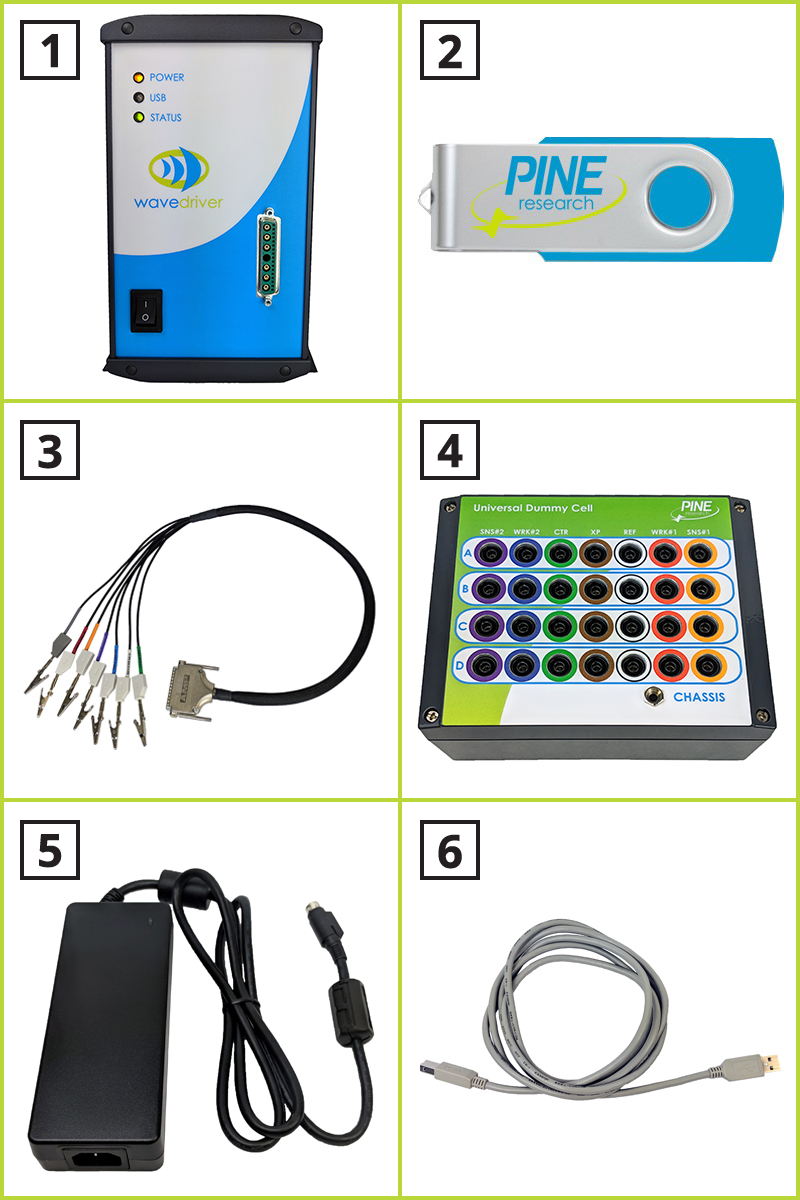
| 1 | Instrument | WaveDriver 40 Bipotentiostat/Galvanostat |
| 2 | USB Flash Drive | Contains AfterMath software, drivers, and license files |
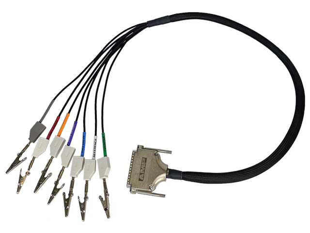
| 3 | Cell Cable | General purpose cell cable with six coaxial electrode cables and one instrument chassis connector (see Section 5 for details) |
| 4 | Universal Dummy Cell | A network of test circuits used to verify proper instrument operation (see Section 2.8 for details)
|
| 5 | Power Supply | Input Requirements: 100 to 240 VAC, 1.4 to 0.7 A, 50 to 60 Hz; Output Power: 24 VDC, 5.0 A; Power supply (included) has a C14 type input connector compatible with a variety of international power cords (sold separately, see Section 7) |
| 6 | Interface (USB) Cable | Communication cable between computer and WaveDriver 40 (USB type A male to type B male) |
Table 7. Main Components Included with WaveDriver 40 Bipotentiostat
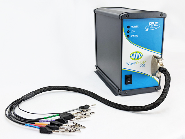
2.6Front Panel
The front panel of the WaveDriver 40 has three LED indicators, the power switch, the cell cable port, and a logo indicating Pine Research as the manufacturer of the instrument (see Table 8). The three LEDs indicate power, communications activity (USB), and overall instrument status. Various colors and blink patterns are used by the LED indicators (see Table 9).
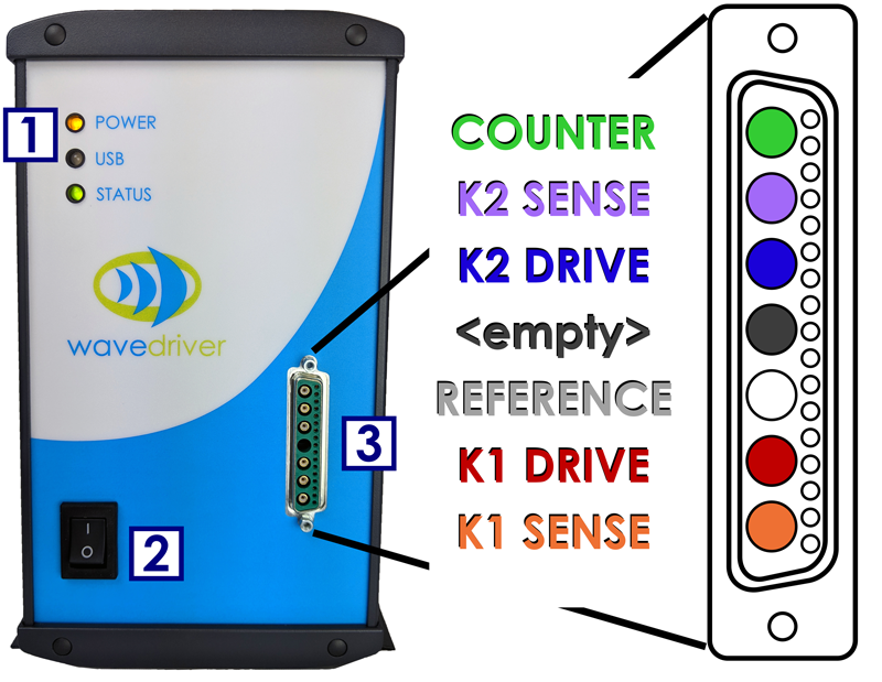
| 1 | LED Indicator Lights | LEDs indicate status of the instrument |
| 2 | Power Switch | Controls whether power is “on” (|) or “off” (⭘) |
| 3 | Cell Cable Port | Provides connection between instrument and cell cable |
Table 8. Front Panel of the WaveDriver 40 Bipotentiostat
| LED | LED Color/State | Indication |
| Power |  not illuminated not illuminated |
When the power LED is not illuminated, the instrument power switch is in the “off” position (or the power supply is not providing power). |
 solid yellow solid yellow |
When the power LED is solid yellow, the power supply is providing power to the instrument and the power switch is in the “on” position. | |
| USB |  blinking green blinking green |
When the USB LED is blinking (or flickering), data transfer is occurring between the instrument and the computer. |
| not illuminated |
When the USB LED is not illuminated, no data is being transferred between the instrument and computer. | |
| Status | slow blinking green |
When the status LED is green and blinking slowly (one second illuminated, one second not illuminated), successful communication has occurred between the instrument and the AfterMath software, and the instrument is presently idle (i.e., not performing an experiment). |
| fast blinking green |
When the status LED is green and blinking quickly (half second illuminated, half second not illuminated), the instrument is performing an experiment. | |
 blinking orange blinking orange |
When the status LED is orange and blinking, the instrument is performing a self-test (immediately after being powered on), or the instrument is waiting for the AfterMath software to establish initial communication with the instrument. | |
 solid or blinking red solid or blinking red |
When the status LED is red (either blinking or solid), there is a serious problem with the instrument. Contact Technical Service for assistance.
|
Table 9. Overview of WaveDriver 40 Bipotentiostat LED Indicator Lights
2.7Back Panel
The back panel of the WaveDriver 40 features several input and output connections to facilitate connection to other instruments and devices (see Figure 3 and Table 10 below). Pinouts for the three control ports (labeled “A”, “B”, and “C” in the “CONTROL PORTS” box on the back panel – see Figure 3) are also provided (see Figure 4). Control ports A and B are specifically designed to control an electrode rotator, while control port C is a non-specific digital control port.
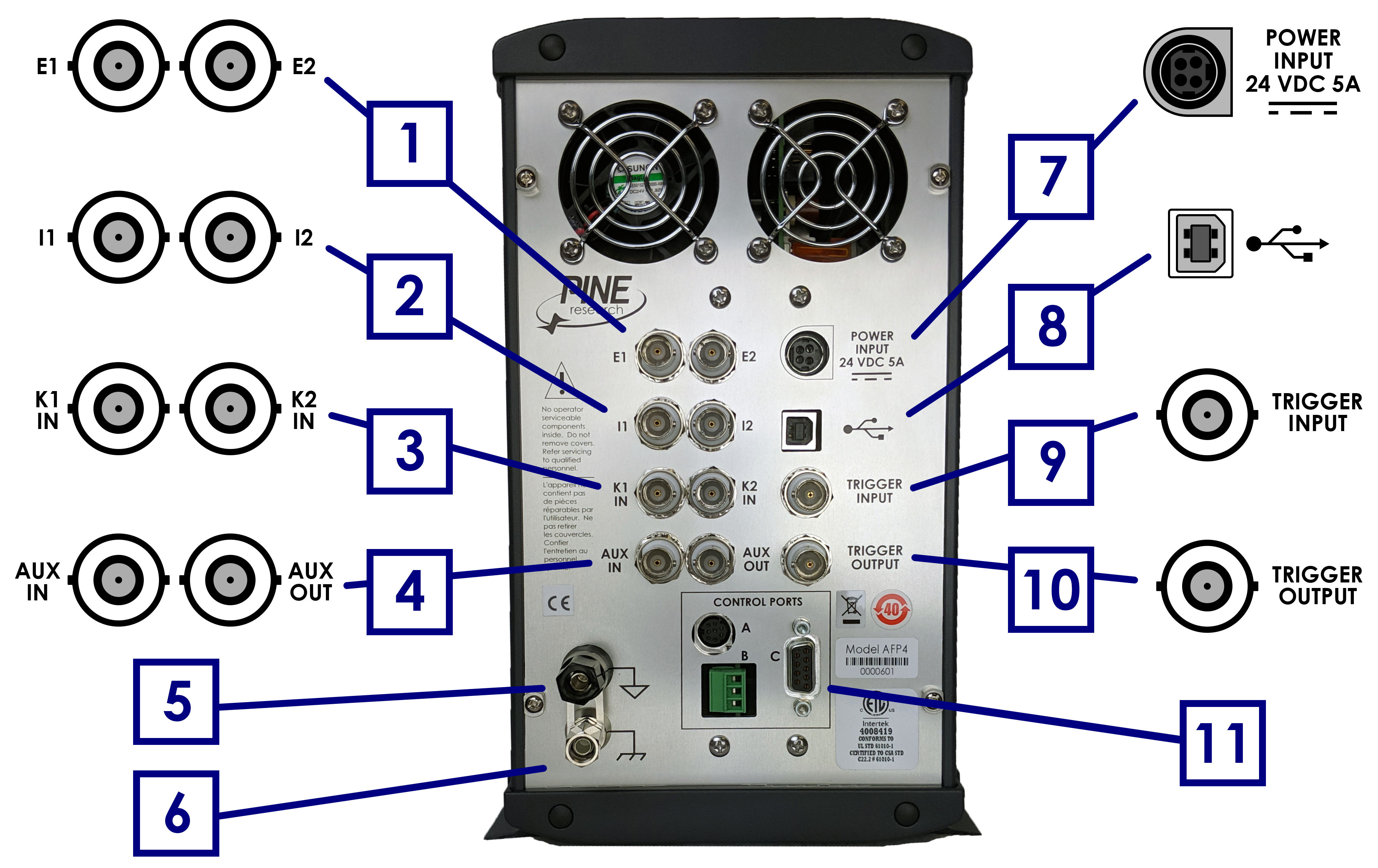
Figure 3. WaveDriver 40 Back Panel Connections
| Number in Fig. 3 | Name | Description |
| 1 | E1 | BNC female, potential output from first working electrode (K1) |
| E2 | BNC female, potential output from second working electrode (K2) | |
| 2 | I1 | BNC female, current output from first working electrode (K1) |
| I2 | BNC female, current output from second working electrode (K2) | |
| 3 | K1 IN | BNC female, ±10 V differential input, 20 kΩ impedance, ±0.5% accuracy; sums an external waveform to first working electrode (K1) |
| K2 IN | BNC female, ±10 V differential input, 20 kΩ impedance, ±0.5% accuracy; sums an external waveform to the second working electrode (K2) | |
| 4 | AUX IN | BNC female, ±10 V differential input, 313 μV resolution, 20 kΩ impedance, 0.2% accuracy; available only when K2 electrode not in use |
| AUX OUT | BNC female, ±10 V bipolar output, 313 μV resolution, 0.2% accuracy; available only when K2 electrode not in use | |
| 5 | DC Common Terminal | |
| 6 | Chassis Terminal | |
| 7 | Power Input | A low voltage (24.0 VDC, 5.0 A) power input connector |
| 8 | USB Input | USB jack (type B) for computer communication |
| 9 | Trigger Input | BNC female, TTL compatible |
| 10 | Trigger Output | BNC female, TTL compatible |
| 11 | Rotator Control Port A | 7-pin mini-DIN input for rotator control – includes analog and digital signal grounds, digital rotator enable signal (+15 V max), auxiliary digital output signal, and analog rotation rate control signal |
| Rotator Control Port B | 3-pin terminal block connector for rotator control – includes analog signal ground, digital rotator enable signal (open drain – TTL compatible, +15 V max), and analog rotation rate control signal (±10 V, ±2.5 V) | |
| Digital Port C | 9-pin D-Sub connector that includes digital signal ground, two digital output signals, and two digital input signals |
Table 10. WaveDriver 40 Back Panel Connector Descriptions
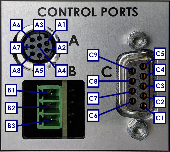 |
|||
| Pin | Signal | Pin | Signal |
| A1 | Unused | B3 | Digital rotator enable signal |
| A2 | Auxiliary digital output signal | C1 | Unused |
| A3 | Unused | C2 | Digital signal input 2 |
| A4 | Analog rotation rate control signal | C3 | Digital signal input 3 |
| A5 | Digital signal ground | C4 | Digital signal output 2 |
| A6 | Unused | C5 | Digital signal output 3 |
| A7 | Digital rotator enable signal | C6 | +5 V digital output |
| A8 | Analog signal ground | C7 | Digital signal ground |
| B1 | Analog rotation rate control signal | C8 | Digital signal ground |
| B2 | Analog signal ground | C9 | Digital signal ground |
2.8Dummy Cell Description
A dummy cell is a network of known resistors and capacitors that can be used to test a potentiostat to ensure that it is working properly. The dummy cell included with the WaveDriver 40 is called the Universal Dummy Cell, and its details and description can be found here:
WaveDriver Dummy Cell Descriptions
3System Installation
Setting up the WaveDriver 40 system in a laboratory consists of three basic steps: (1) physical installation, (2) software installation, and (3) system testing and cell cable calibration. The entire process usually requires about sixty minutes. The physical and software installation steps are described in this section (below), and the system testing and cell cable calibration procedures are described in the next section (see Section 4).
3.1Physical Installation
The WaveDriver 40 is a benchtop instrument designed for use in a typical laboratory environment. Physical installation involves positioning the instrument and the computer that controls the instrument in a suitable location and connecting the instrument to a source of electrical power (i.e., the AC Mains) and to the computer via a USB cable.
3.1.1Location
The instrument should be placed on a sturdy lab bench or table in such a way that there is unobstructed access to the instrument’s front panel; this ensures space for the cell cable connection and allows the user to easily operate the power switch and see the LED lights. There should also be at least two inches (50 mm) of clearance around the sides (left, right, and back) and above (top) the instrument. Particular care should be given to selecting a clean and dry location. The vent fans on the back panel must not be blocked so that adequate ventilation is available for cooling the circuitry inside the instrument.
During normal use, the instrument is connected to an electrochemical cell via a cell cable plugged into the front panel of the instrument. Thus, it is important to ensure that the lab bench or table also has sufficient workspace for securely mounting the electrochemical cell and for routing the cell cable between the instrument and the electrochemical cell.
3.1.2Glovebox Installation
The WaveDriver 40 and/or the electrochemical cell can be placed inside a glovebox to perform specialized experiments. More information can be found here:
Potentiostat Glovebox Installation
3.1.3Connecting the Power Supply to the Instrument
The power supply provides the DC power required by the instrument (24 VDC, 5.0 A) via a low voltage cable. One end of the low voltage cable is permanently connected to the power supply, and the other end is connected to the POWER INPUT port located on the back panel of the instrument (see Figure 5).
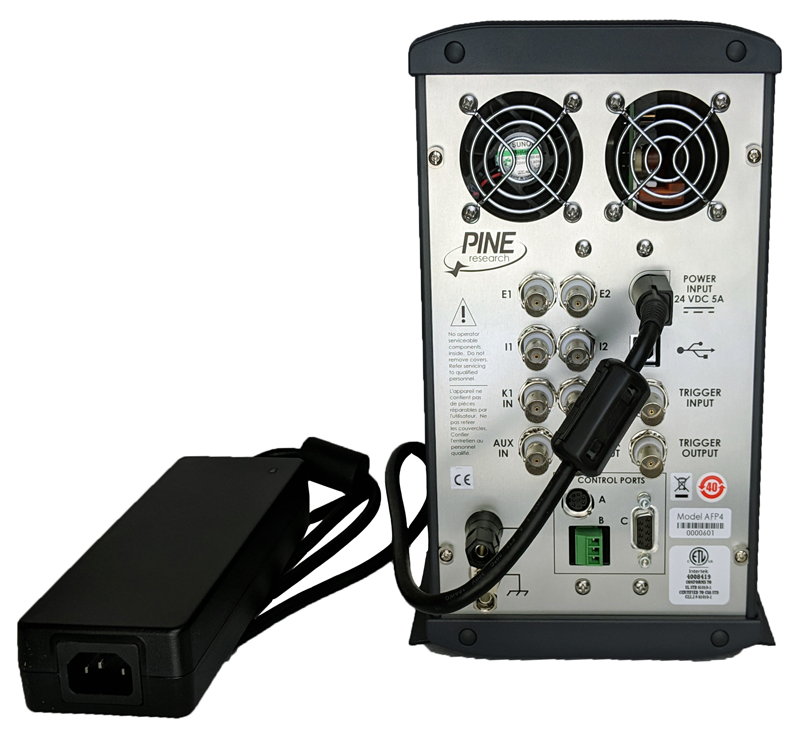
When connecting the low voltage power cable to the POWER INPUT port on the back panel, take note that the connector will only fit into the port using one particular orientation. The side of the cable connector which is completely flat must be oriented to the right when plugging the connector into the port.
When properly installed, the low voltage power cable will securely latch into the POWER INPUT port. When unplugging the low voltage power cable from the port, it is important to release this latch correctly. Grip the connector firmly near the flat part of the connector. Then, pull the connector straight out (do not twist the connector).
3.1.4Connecting the Power Supply to the AC Mains
The WaveDriver 40 power supply is connected to the AC Mains via an AC power cord.
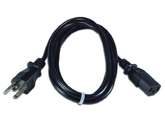 Standard 10 Amp Power Cords
The AC power cord must be rated to carry at least 10 Amps. One end of the AC power cord is connected to the standard C14 connector on the power supply, and the other end is connected to the AC Mains (wall outlet). Pine Research offers power cords suitable for use in a variety of different countries and regions (see Section 7).
Standard 10 Amp Power Cords
The AC power cord must be rated to carry at least 10 Amps. One end of the AC power cord is connected to the standard C14 connector on the power supply, and the other end is connected to the AC Mains (wall outlet). Pine Research offers power cords suitable for use in a variety of different countries and regions (see Section 7).The local source of electrical power (i.e., the AC Mains) must be a branch circuit protected by a circuit breaker rated between 10 and 15 Amps. The AC voltage supplied by the AC Mains must be between 100 and 240 VAC, and the AC frequency must be between 50 and 60 Hz. The power supply and AC power cord must be positioned such that the user has unobstructed access to these items. The user must be able to disconnect the instrument from the power supply and disconnect the power supply from the AC mains (wall outlet) without any obstructions.
3.2AfterMath Software Installation
AfterMath is designed to be installed on a personal computer (PC) using a Windows-based operating system, and is not compatible with Apple products or operating systems at this time. AfterMath system requirements can be found here:
AfterMath System Requirements
3.2.1Step-by-Step Software Installation Instructions
AfterMath installation media is included with the WaveDriver 40. The installation media contains the latest release of AfterMath available at the time of purchase, the device drivers for communicating with the instrument, and the permissions files that implement the software license. Installation instructions for AfterMath software can be found here:
AfterMath Installation Guide
3.2.2Permissions File Verification
On the installation media, there are license files, or “permissions files”, which authorize a computer running AfterMath to control specific instruments. Information on permissions files can be found here:
AfterMath Installation Guide
3.3USB Cable Connection
The WaveDriver 40 connects to a computer using the USB cable supplied with the instrument (Type A male to Type B female USB cable). Information on the USB cable connection can be found here:
AfterMath Installation Guide
3.4Installation Checklist
The next section of this guide will describe testing and calibrating a fully-installed WaveDriver 40. Before proceeding, ensure the following installation steps have been completed:
- The WaveDriver 40 instrument is located in a secure, dry location with adequate space
- Electrical power is connected to the WaveDriver 40
- AfterMath software is installed on the computer
- The WaveDriver 40 instrument is connected to a computer via the USB cable
4System Testing
This section describes how to test the WaveDriver 40 system. By connecting the bipotentiostat to a well-behaved network of resistors and capacitors (using the Universal Dummy Cell),
WaveDriver Dummy Cell Descriptions
the bipotentiostat circuitry can be tested to assure that it is working properly.
4.1Test Setup
Testing a WaveDriver 40 involves several steps. This section can be viewed in detail on the following post:
Testing Potentiostat Setup
4.2Single Channel (K1) DC Test
The single channel DC test for the WaveDriver 40 involves several steps. This section can be viewed in detail on the following post:
WaveDriver Single Channel (K1) DC Test
4.3Dual Channel (K1 and K2) DC Test
The dual channel DC test for the WaveDriver 40 involves several steps. This section can be viewed in detail on the following post:
WaveDriver Dual Channel (K1 and K2) DC Test
5Cell Cable Connections
This section describes how to connect several different kinds of electrochemical cells to the WaveDriver 40. Before proceeding, the user should be familiar with general concepts associated with electrochemical cells and experimentation. Using the WaveDriver 40 Cell Cable (part number ACP3E01),
 WaveDriver Bipotentiostat Cell Cable
connections can be made to simple two-terminal cells (such as batteries, fuel cells, solar cells, amperometry sensors, capacitors, resistors, and inductors), traditional three-electrode voltammetry cells (including those which contain a rotating disk electrode or a rotating cylinder electrode), compact voltammetry cells, and to more complex dual working electrode cells (including rotating ring-disk electrode cells).
WaveDriver Bipotentiostat Cell Cable
connections can be made to simple two-terminal cells (such as batteries, fuel cells, solar cells, amperometry sensors, capacitors, resistors, and inductors), traditional three-electrode voltammetry cells (including those which contain a rotating disk electrode or a rotating cylinder electrode), compact voltammetry cells, and to more complex dual working electrode cells (including rotating ring-disk electrode cells). 5.1Cell Cable Color Code
The front panel of the WaveDriver 40 has a large cell connection port containing several signal lines that may be connected to the various working, counter, and reference electrodes that may be present in an electrochemical cell. It is important to understand that some of the signal lines are low impedance DRIVE lines while others are high impedance SENSE lines. In general, the DRIVE lines are used to drive current through the electrochemical cell while the SENSE lines are used to carefully measure the potential at various electrodes.
More details on the WaveDriver 40 cell cable, including color code descriptions and cable pinout, can be found on the following post:
WaveDriver Bipotentiostat Cell Cable
5.2Experimental Configurations
With the proper cell cable configuration, several kinds of electrochemical systems can be connected to the WaveDriver 40. The following discussion of cell cable configurations assumes prior familiarity with the concepts associated with each type of electrochemical cell.
The WaveDriver 40 Cell Cable has a D-Shell connector that fits the cell cable port located on the front panel of the instrument. There are two thumbscrews on the D-Shell connector that tighten into the cell cable port to provide a secure connection (see Figure 6).
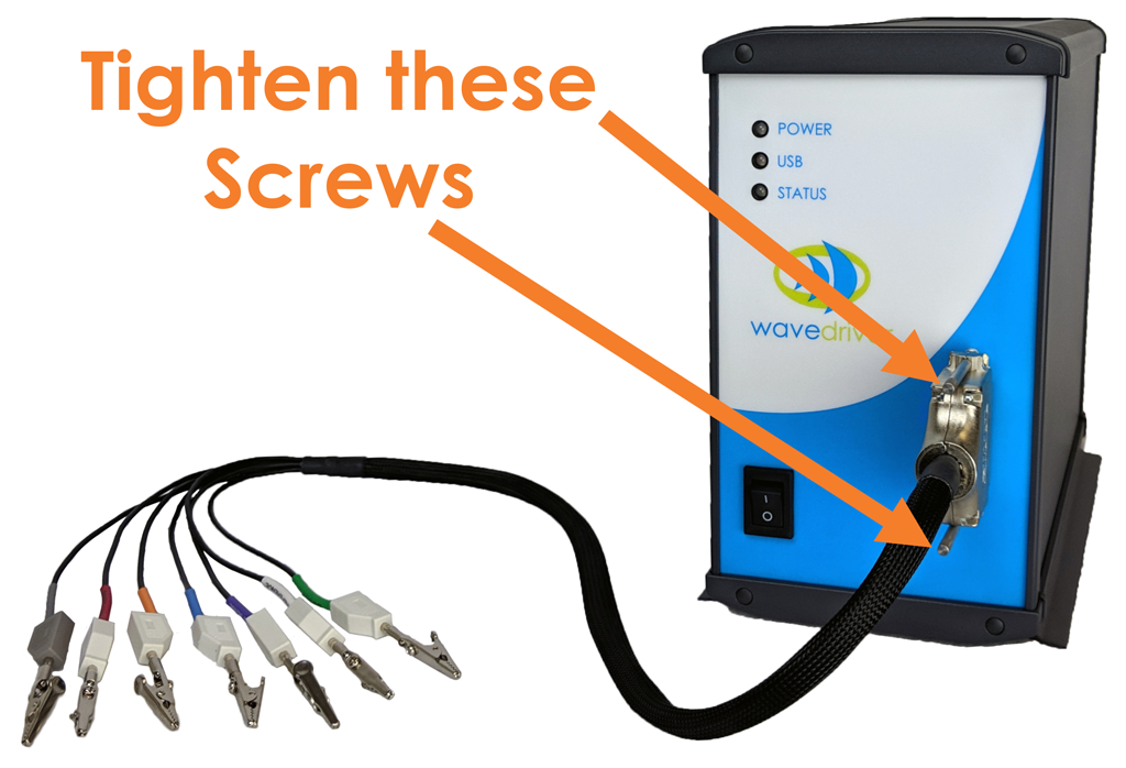
Figure 6. Secure Connection of the WaveDriver 40 Cell Cable to the Cell Port
As the cell cable emerges from the D-Shell connector, a conductive mesh shield runs along most of the length of the cable. This mesh shield is electrically-connected to the chassis of the instrument and provides additional protection from environmental noise and ESD events.
At the cell end of the cable, multiple signal lines emerge from the mesh sleeve and terminate in banana plugs. All of these signal lines (except for the GRAY chassis line) are coaxial. The outer (shield) portion of each coaxial line further protects sensitive signals from environmental noise. Alligator clips (included) may optionally be installed on the banana plugs as needed.
When the WaveDriver 40 is not being used as a bipotentiostat (i.e., when there is not a second working electrode present in the cell), the banana plugs for the BLUE and VIOLET leads should be stacked together and set aside (see Figure 7). To prevent these leads from coming into contact with any conductive surface, they can optionally be placed inside a plastic bag.
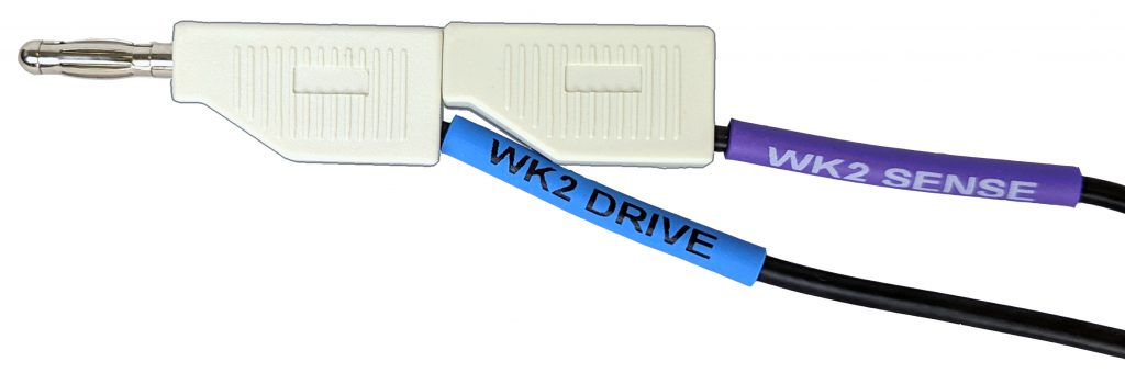
Figure 7. Unused K2 Electrode Lines
5.2.1Two-Electrode Setups
Typical examples of two-electrode setups are solid-state experiments that probe electrochemical behavior across a single interface, experiments that involve ion-selective electrodes (where the open circuit potential is measured between an ion-selective electrode and a reference electrode), and rechargeable batteries consisting of an anode and cathode. Simple experiments with common electronic components (resistors, capacitors, and inductors) also use a two-electrode arrangement.
More details on two-electrode setups can be found on the following post:
Two-Electrode Setups
5.2.2Three-Electrode Cells
In a traditional three-electrode cell, three different electrodes (working, counter, and reference) are placed in the same electrolyte solution. During three-electrode experiments, charge flow (current) primarily occurs between the working electrode and the counter electrode while the potential of the working electrode is measured with respect to the reference electrode. The WaveDriver 40 Cell Cable can be configured for three-electrode experiments by appropriate connection of the drive and sense lines.
More details on three-electrode setups can be found on the following post:
Three-Electrode Setups
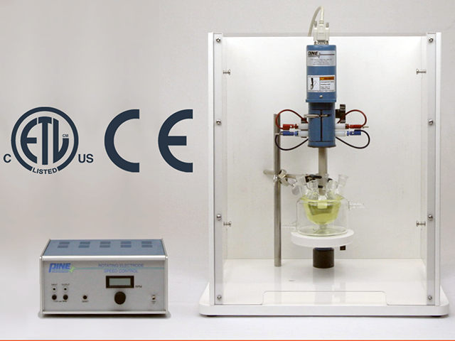
5.2.3Rotating Disk and Rotating Cylinder Electrodes (RDE and RCE)
The WaveDriver 40 may be used in conjunction with an electrode rotator to perform Rotating Disk Electrode (RDE) or Rotating Cylinder Electrode (RCE) experiments. These experiments are hydrodynamic variations of traditional three-electrode voltammetry.
Three-Electrode Setups
Rotating the working electrode (which may have a disk or cylinder geometry) at a controlled rate establishes convective mass transfer of electrolyte solution (and dissolved electroactive species) towards the electrode surface. Connecting the potentiostat to a hydrodynamic experiment involves not only making connections to the electrodes (working, counter, and reference) but also providing a rotation rate control signal to the electrode rotator.
More details on RDE and RCE setups can be found on the following post:
Rotating Disk and Rotating Cylinder Electrode Setups (RDE and RCE)
5.2.4Rotating Ring-Disk Electrodes (RRDE)
A rotating ring-disk electrode (RRDE) cell contains a total of four electrodes – two working electrodes (disk and ring), one counter electrode, and one reference electrode. During an RRDE experiment, the WaveDriver 40 operates as a bipotentiostat, measuring the currents at the disk and ring electrodes (charge flows between the ring, the disk, and the counter electrode) while simultaneously measuring the potentials of the disk and ring electrodes with respect to the single reference electrode.
More details on RRDE setups can be found on the following post:
Rotating Ring-Disk Electrode Setups (RRDE)
5.2.5Rotation Rate Control
Many electrode rotators can accept rotation rate control signals from a potentiostat. The WaveDriver 40 instrument provides both a digital “on/off” signal and an analog rotation rate signal that can be used to control the motor on an electrode rotator. These signals output from a connector on the back panel of the WaveDriver 40 (see Table 10). Special cables are available from Pine Research that may be used to connect these signals to various electrode rotator models.
More details regarding automated control of Pine Research rotators can be found here,
Automated Control of Electrode Rotators
while directions on altering the input rotation rate for the MSR rotator can be found here:
Changing Input Rotation Rate on MSR Rotator
Connecting a Pine Research WaveDriver 40 to a Pine Research MSR rotator
 Modulated Speed Rotator (MSR)
requires a special cable (part number AKCABLE4).
Modulated Speed Rotator (MSR)
requires a special cable (part number AKCABLE4).
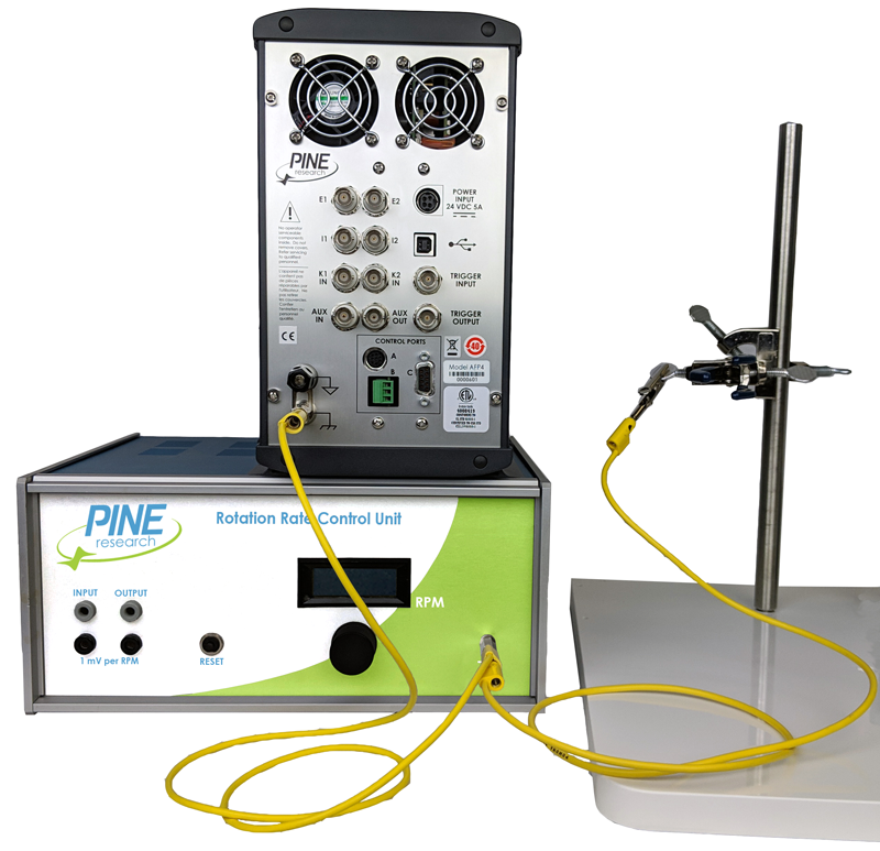
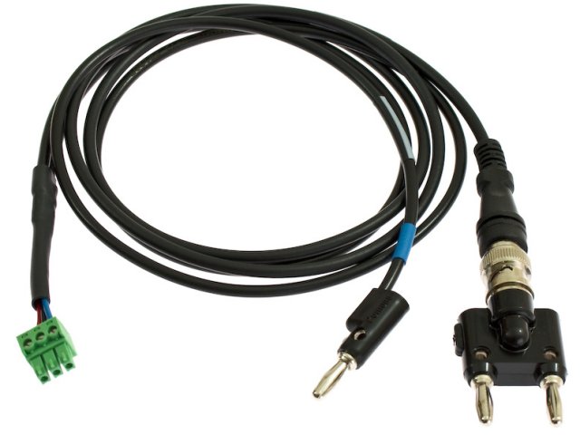 MSR Rotation Rate Control Cable (3-pin)
One end of this cable has a small green connector which fits into Control Port “B” on the back panel of the WaveDriver 40. The other end of the cable connects to the MSR control unit at two locations (see Figure 8). The coaxial portion of the cable connects to the pair of INPUT jacks on the front panel of the control unit. The other part of the cable terminates at a banana plug which is connected to the MOTOR STOP jack on the back panel of the control unit.
MSR Rotation Rate Control Cable (3-pin)
One end of this cable has a small green connector which fits into Control Port “B” on the back panel of the WaveDriver 40. The other end of the cable connects to the MSR control unit at two locations (see Figure 8). The coaxial portion of the cable connects to the pair of INPUT jacks on the front panel of the control unit. The other part of the cable terminates at a banana plug which is connected to the MOTOR STOP jack on the back panel of the control unit.
Modulated Speed Rotator (MSR)
requires a special cable (part number AKCABLE4).
MSR Rotation Rate Control Cable (3-pin)
One end of this cable has a small green connector which fits into Control Port “B” on the back panel of the WaveDriver 40. The other end of the cable connects to the MSR control unit at two locations (see Figure 8). The coaxial portion of the cable connects to the pair of INPUT jacks on the front panel of the control unit. The other part of the cable terminates at a banana plug which is connected to the MOTOR STOP jack on the back panel of the control unit.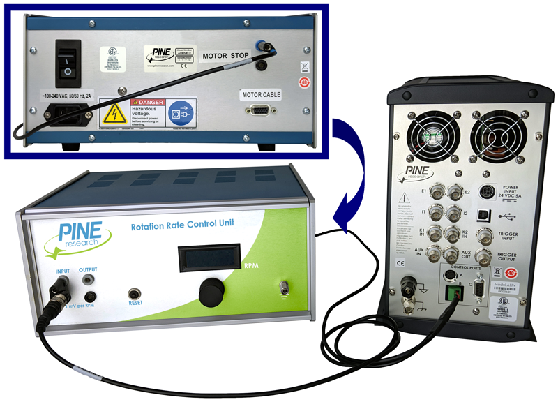
Connecting a Pine Research WaveDriver 40 to a Pine Research WaveVortex 10 rotator
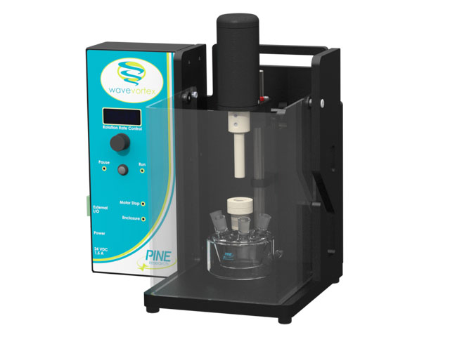 WaveVortex 10 Electrode Rotator
requires a special cable (part number AKCABLE7-03).
WaveVortex 10 Electrode Rotator
requires a special cable (part number AKCABLE7-03).
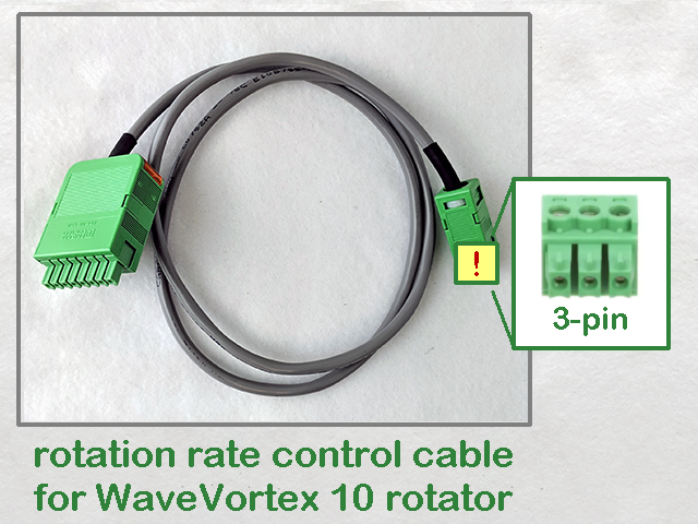 WaveVortex 10 Rate Control Cable (3-pin)
One end of this cable has a small green connector which fits into Control Port “B” on the back panel of the WaveDriver 40. The other end of the cable terminates at a large green connector which fits into the control port on the side of the WaveVortex 10 control unit (see Figure 9).
WaveVortex 10 Rate Control Cable (3-pin)
One end of this cable has a small green connector which fits into Control Port “B” on the back panel of the WaveDriver 40. The other end of the cable terminates at a large green connector which fits into the control port on the side of the WaveVortex 10 control unit (see Figure 9).
WaveVortex 10 Electrode Rotator
requires a special cable (part number AKCABLE7-03).
WaveVortex 10 Rate Control Cable (3-pin)
One end of this cable has a small green connector which fits into Control Port “B” on the back panel of the WaveDriver 40. The other end of the cable terminates at a large green connector which fits into the control port on the side of the WaveVortex 10 control unit (see Figure 9).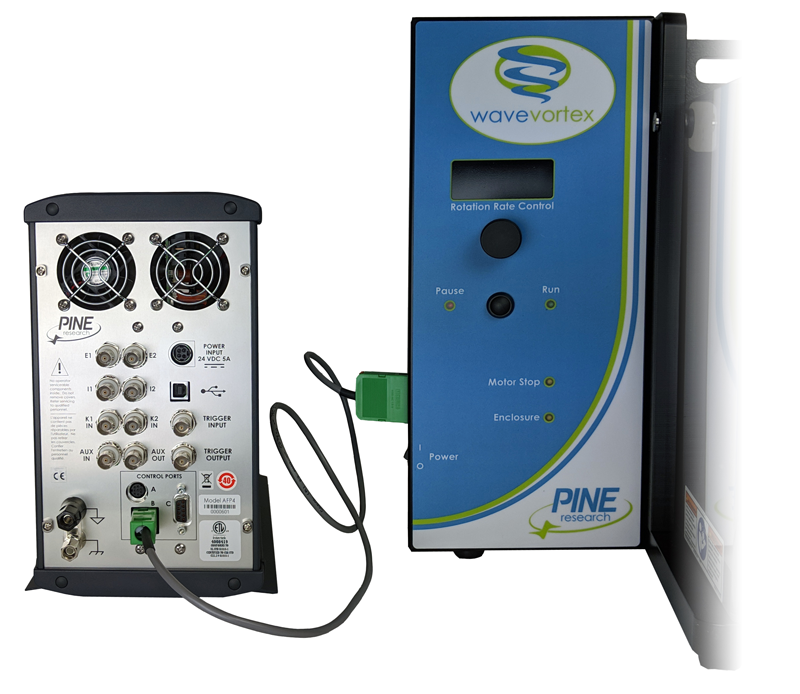
Connects WaveVortex 10 rotator to any Pine Research potentiostat with a 3-pin connector on back panel
5.2.6Compact Voltammetry Cell Cable Connections
More details on connecting a WaveDriver 40 to the Pine Research compact voltammetry cell will be available at a later date.
6Grounding Information
The general goal of an experiment grounding strategy is to reduce the level of signal noise in the electrochemical measurement caused by noise sources in the laboratory environment. To avoid issues with laboratory noise sources, it is important to properly ground all metal objects near an electrochemical setup and to make appropriate grounding connections between the potentiostat and any other electronic equipment used as part of the experiment.
Detailed information on general instrument grounding, including common noise sources (Section 6.1), grounding terminology (Section 6.2), Faraday cages (Section 6.3), metal apparatus (Section 6.4), and USB isolation (Section 6.5) can be found here:
General Instrument Grounding Information
6.1Common Noise Sources
Information on common noise sources can be found in the post detailing general instrument grounding:
General Instrument Grounding Information
6.2Grounding Terminology
A potentiostat or other piece of electronic equipment generally has three types of grounding connections that are often confused with one another: the earth ground, the chassis terminal, and the DC Common. These are discussed in more detail in the post detailing general instrument grounding:
General Instrument Grounding Information
6.3Faraday Cages
Information on Faraday cages can be found in the post detailing general instrument grounding:
General Instrument Grounding Information
6.4Metal Apparatus
Information on metal apparatus can be found in the post detailing general instrument grounding:
General Instrument Grounding Information
6.5USB Isolation
Information on USB isolation can be found in the post detailing general instrument grounding:
General Instrument Grounding Information
6.6Grounding Strategies
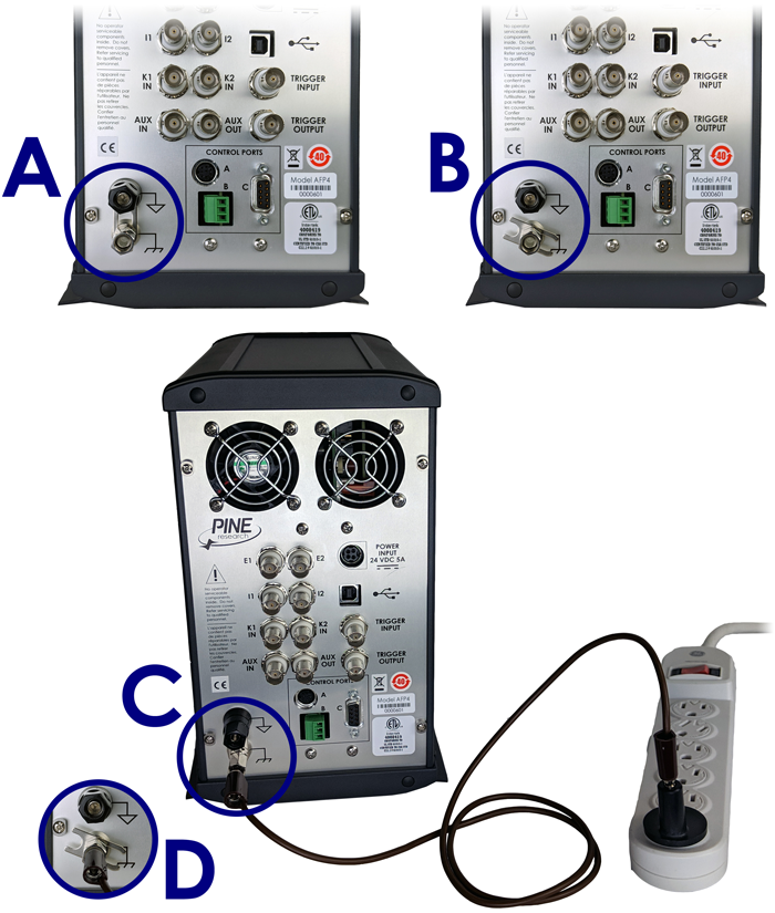
The first step in determining the optimal grounding configuration for any electrochemical experiment is to understand the grounding configuration of the potentiostat itself. There are several possible ways in which the instrument chassis, the DC Common, and the earth ground might be connected. A summary of the most common configurations is provided (see Figure 10).
 |
||||
| Configuration | DC Common | Chassis | Earth Ground | |
 |
 |
 |
||
| A | DC Common-to-Chassis (as shipped from factory) |  |
||
| B | Fully Floating |  |
||
| C | Fully Earth Grounded |  |
||
| D | Chassis-to-Earth Ground |  |
||
Figure 10. Four Common Instrument Grounding Configurations
When the WaveDriver 40 is shipped from the factory, a metal shorting bar is pre-installed on the back panel which bridges the DC Common and instrument chassis banana binding posts (see Figure 10A). This “DC Common-to-Chassis” configuration may be suitable for some electrochemical experiments; however, in other situations it may be better to disconnect this metal shorting bar to obtain a “Fully Floating” condition.
In situations where it is desirable to have a “fully floating” arrangement where the DC Common floats with respect to the instrument chassis, the shorting bar may be disconnected from the DC Common (see Figure 10B). This arrangement is often required when one of the electrodes is actually part of a third-party apparatus (such as a quartz crystal microbalance or an electroplating system), and the third-party apparatus requires that the electrode be connected to the chassis or to the earth ground or to both. In these cases, the DC Common should be allowed to float with respect to the chassis to prevent an inadvertent short-circuit between the electrode and DC Common (via the third-party apparatus).
The WaveDriver 40 is designed so that no part of the instrument circuit is connected to earth ground by default. While the external power supply does have an earth ground connection, the earth ground is not passed through the power supply to the instrument. If desired, a deliberate connection between earth ground and the instrument chassis may be made. Various cables and connectors (not included) can be used to make a connection from the chassis terminal on the back panel of the instrument to the third-prong on a nearby electrical receptacle.
If the chassis is connected to the earth ground, then depending upon the position of the shorting bar, the instrument may have a simple “Chassis–to–Earth Ground” connection (see Figure 10C), or it may be “fully earth grounded” (see Figure 10D). In many cases, connections to earth ground can introduce unknown or unwanted sources of noise in the experimental results. If the experimental setup requires that the instrument be earth grounded, then some trial-and-error may be required to determine whether or not to also connect the DC Common to earth ground.
6.7Grounding Third-Party Instrumentation
When using one or more third-party electronic instruments together with the WaveDriver 40, a common grounding strategy is to connect the chassis of the WaveDriver 40 to the chassis of the other instrument(s). All such connections should be brought together to a single point. Any other metal objects located near the electrochemical cell (e.g., ring stands, Faraday cage, clamps, etc.) should be connected to the same single point to avoid creating a possible grounding loop (see Figure 11).
When using third-party instrumentation, a decision must be made regarding whether or not to connect the chassis terminal to the earth ground. Some third-party equipment may actually force such a connection to earth ground, and sometimes this connection is hidden from view inside the third-party instrument. Trial-and-error, as well as the use of an ohmmeter, may be required to analyze and fully understand the grounding configuration when multiple instruments are used together.
Just like the WaveDriver 40, third-party instruments also have their own DC Common line which represents the common “zero volt” analog signal level within the third-party instrument’s circuit. When the WaveDriver 40 is connected to an electrode rotator control unit, a spectrometer, a quartz crystal microbalance, or other third-party instrument, a connection is almost always made between the DC Common lines of the various instruments. In these cases, it is important to be aware of whether or not the DC Common of a third-party instrument happens to also be connected to earth ground or to the instrument chassis. Such connections are sometimes hidden within the third-party instrument. Again, some trial-and-error, as well as the use of an ohmmeter, may be required to confirm whether or not the DC Common is floating with respect to the chassis (or with respect to earth ground).
7Power Cords
The standard C14 connector on the WaveDriver 40 power supply is compatible with a wide range of power cords available from Pine Research. Each of the available power cords is rated at 10 A (minimum), and each cord is designed for use in a specific country or region of the world. Representative images and Pine Research part numbers are provided here:
Standard 10 Amp Power Cords
Standard 10 Amp Power Cords
8Glossary
A glossary of selected electrochemistry terms can be found here:
Glossary
9Customer Support
After reviewing the content of this user guide, please contact Pine Research should you have any issues or questions with regard to the use of the instrument, accessories, or software.
Contact us anytime by the methods provided below:
9.1Online
Contact Pine Research any time via our website:
Contact
9.2Email
Send an email to pinewire@pineresearch.com. This is the general sales email and our team will ensure your email is routed to the most appropriate technical support staff available. Our goal is to respond to emails within 24 hours of receipt.
9.3Phone
Our offices are located in Durham, NC in the eastern US time zone. We are available by phone Monday through Friday from 9 AM EST to 5 PM EST. You can reach a live person by calling +1 (919) 782-8320.