mobile-main-menu-button
Menu

How can we help? What do you want to learn? Search our knowledgebase.

Use and Assembly of the Advanced Low Volume Membrane Kit

Last Updated: 8/21/19 by Neil Spinner

Download as PDF
ARTICLE TAGS
  • membrane kit,
  • membrane cell,
  • low volume,
  • DRP10245,
  • advanced,
  • separated cell
Article Contents/Section Navigation
  1. Abstract
  2. Advanced Low Volume Membrane Kit Assembly
    1. Membrane Kit Items and Assembly
    2. Sealing Electrodes and Purge/Sparge Tubes in Cap Kit

1Abstract

This product information document will describe how to assemble the Advanced Low Volume Membrane Kit. Advanced Low Volume Membrane Kit I The cell is designed to diffusionally isolate half-reactions using a membrane or separator, which is supplied by the researcher.  The cell is not a pressure vessel, so if any insert gas is added (e.g., using a purge/sparge tube), be sure to add a vent in the headspace.  This is true for both sides of the cell, as gas will not easily pass from one half to the other with traditional membranes.
Back To Top

2Advanced Low Volume Membrane Kit Assembly

2.1Membrane Kit Items and Assembly

The Advanced Low Volume Membrane Kit (Pine Research bundle part number [MEM-1]) Advanced Low Volume Membrane Kit I comes with the items shown below (see Figure 1).
 
Hardware included with the Advanced Low Volume Membrane Kit

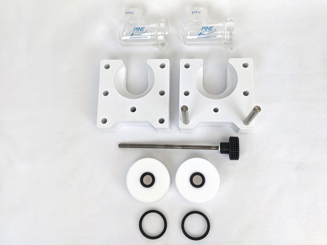
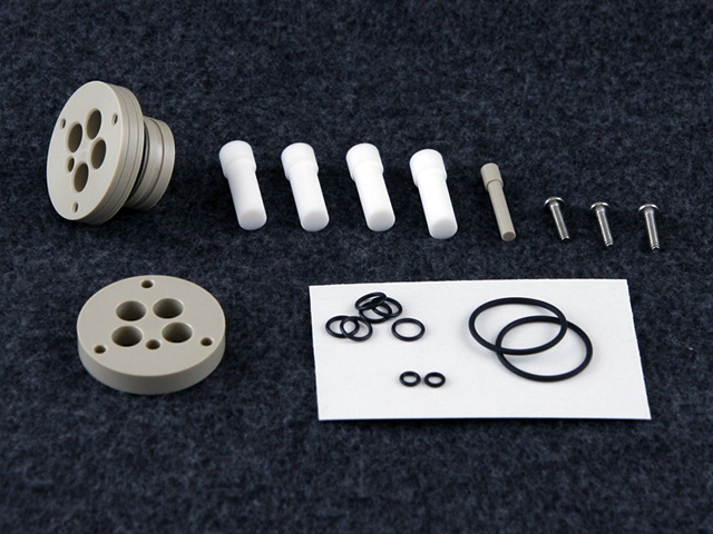
Figure 1. Hardware included with the Advanced Low Volume Membrane Kit

 
To assemble the membrane kit, first arrange the two PET frame pieces (Pine Research part number AF01CKT1021) directly facing each other as shown in the image below (see Figure 2).  One of the frame pieces has two metal centering rods and the other has corresponding holes at the bottom where the rods can be inserted.
 
Arrange the two PET frame pieces facing each other

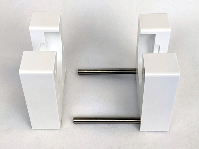
Figure 2. Arrange the two PET frame pieces facing each other

 
The kit comes with two PTFE “pucks” – one for each half cell – as well as two O-rings per puck (see Figure 3).  The standard pucks that come with the [MEM-1] bundle Advanced Low Volume Membrane Kit I (Pine Research part number AC01CKT1021M03) have a 1 cm2 opening, meaning the exposed surface area of the membrane/separator between the two half cells will be 1 cm2.  Pucks with different sized bore openings may be available upon request.
 
Half cell “pucks” (1 cm2 bore area) with O-rings

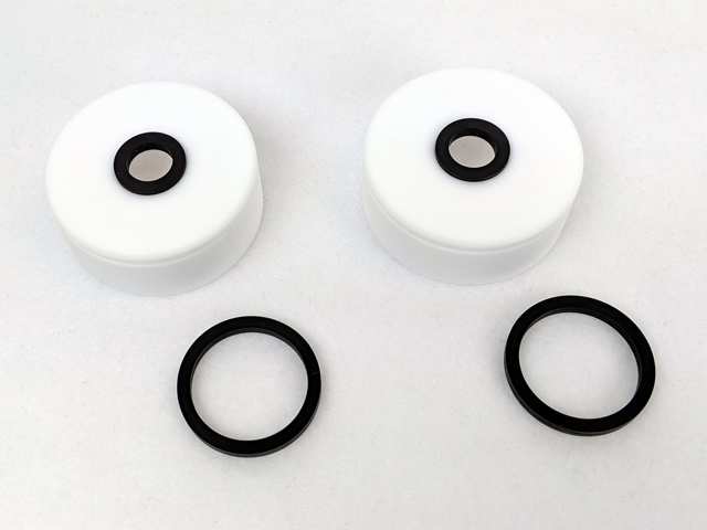
Figure 3. Half cell “pucks” (1 cm2 bore area) with O-rings

 
There are grooves on both sides of each puck where the O-rings sit.  The smaller O-ring can be placed in the groove on the outside, flat surface (see Figure 3), while the larger O-ring fits inside the cavity (see Figure 4).  Insert each glass half cell into their respective puck cavities (see Figure 5).

NOTE: Both pucks and half cells are identical, and can be used interchangeably.

Glass half cell with PTFE puck and both O-rings installed

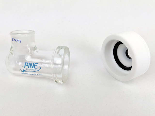
Figure 4. Glass half cell with PTFE puck and both O-rings installed

 
Glass half cells inserted into PTFE pucks

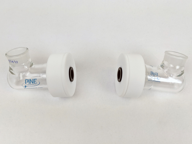
Figure 5. Glass half cells inserted into PTFE pucks

 
Place each half cell-puck combination into the slots in each PET frame piece facing each other (see Figure 6).  The pucks must be first positioned in front of the frame piece grooves and pulled back into the slots to fit properly.  The user will notice that the diameter of the puck and glass cell flange is too wide to be simply dropped straight into the frame slot from above.  This is intentional so that once it has been slipped into the groove, it will remain in place, facilitating easy assembly and centering of each cell half.
 
Half cells and pucks inserted into PET frame pieces

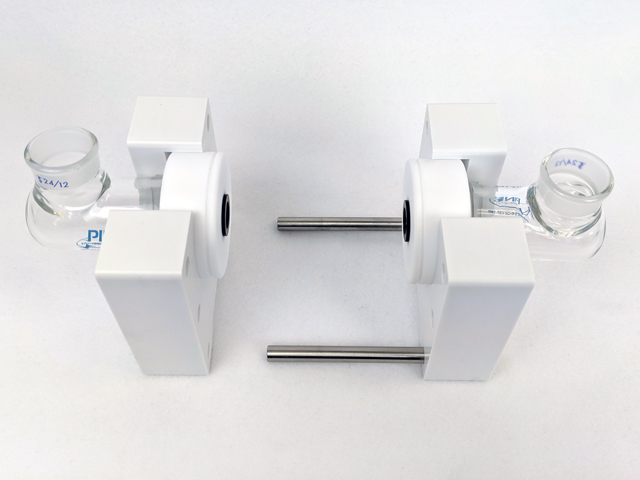
Figure 6. Half cells and pucks inserted into PET frame pieces

 
Begin moving the two frame pieces together, inserting the metal centering rods into the opposing holes as the pieces are closed together.  Insert the long metal screw into the bottom-center hole of the piece from which the metal rods also protrude (see Figure 7).  The opposing bottom-center hole on the other frame piece is threaded.  Start tightening the long screw.
 
Begin tightening the membrane kit together using the long metal screw

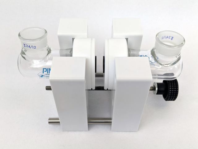
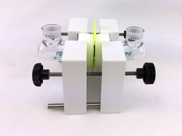
Figure 7. Begin tightening the membrane kit together using the long metal screw

 
Once the two halves are close enough together, a membrane or separator can be put in place.  Final tightening of the long screw will compress both the inner, larger O-rings onto each glass flange, as well as the two outer, smaller O-rings onto each side of the membrane/separator, fully sealing each half cell (see Figure 8).  Be careful not to overtighten the screw as this may compromise the seal and/or damage the O-rings.
 
Fully-assembled Advanced Low Volume Membrane Kit

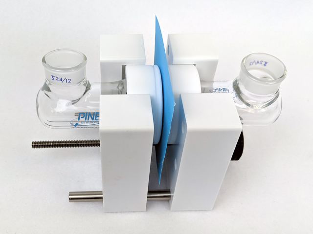
Figure 8. Fully-assembled Advanced Low Volume Membrane Kit

Back To Top

2.2Sealing Electrodes and Purge/Sparge Tubes in Cap Kit

The Low Volume Cell Cap Kit (Pine Research part number AF01CKT1004) Low Volume Cell Series Cap Kit is designed to tightly seal around all LowProfile electrodes (E1B series electrodes) E1B LowProfile Precious Metal Electrodes and purge/sparge tubes.  Once assembled, the cap kit seals into the top 24/12 joints in the membrane kit half cells.  Two cap kits, as well as four purge/sparge tubes (Pine Research part numbers RRPG261 and RRPG262), are included in the Advanced Low Volume Membrane Kit bundle. Advanced Low Volume Membrane Kit I
 
Use of this cell requires a plan prior to experimentation.  You must have identified the working, counter, and reference electrodes and have them prepared and ready to use.  Similarly, decide whether or not you will add gas into the cell and if so, plan for a vent as well (perhaps in the headspace).
 
The cap kit consists of four 7 mm holes and one 3.5 mm hole.  The kit includes appropriately-sized O-rings for use with matching probe diameters.  Pine Research offers working and counter electrodes to fit the 7 mm holes and reference electrodes to fit the 3.5 mm hole.  To take advantage of the sealing aspect of the lid, select the appropriate plug to use in any hole that does not contain a probe.
 
The basic principle of the cap kit is to seal all probes (i.e., electrodes) into the cap by wedging a soft O-ring between the upper and lower halves of the cap and clamping the halves together to seal any gaps.  Then, the assembled cap kit seals directly into the half cells.  The following images will walk through the steps to position and seal the electrodes in the cap.
 
With the thin aspect of the cap kit, insert a probe (a purge tube in this image) through the appropriate hole and add an O-ring.

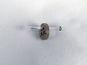
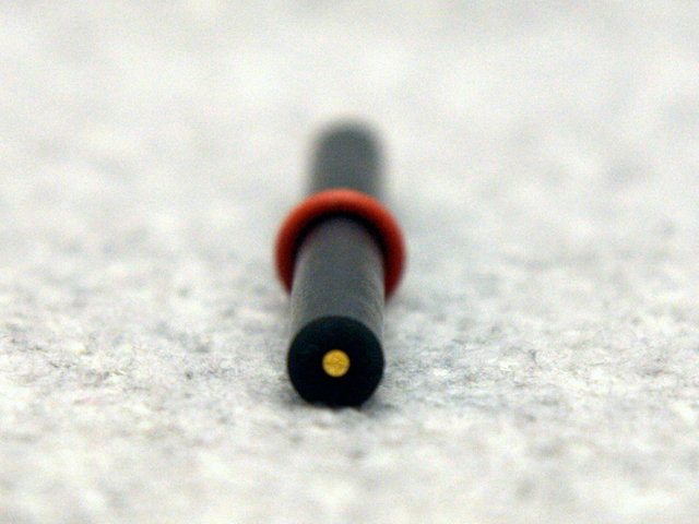
Figure 9. With the thin aspect of the cap kit, insert a probe (a purge tube in this image) through the appropriate hole and add an O-ring.

 
Repeat the probe and O-ring insertion for each type of electrode, plug, or glass tube. Take special caution to appropriately adjust the height of the O-ring to ensure the assembled cap will fit into the cell without the probes hitting the bottom of the cell surface.

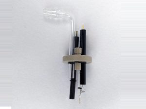
Figure 10. Repeat the probe and O-ring insertion for each type of electrode, plug, or glass tube. Take special caution to appropriately adjust the height of the O-ring to ensure the assembled cap will fit into the cell without the probes hitting the bottom of the cell surface.

 
Invert the cap so that the probes are held in place when the O-ring hits the cap. Again, adjust height appropriately.

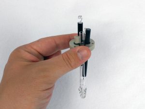
Figure 11. Invert the cap so that the probes are held in place when the O-ring hits the cap. Again, adjust height appropriately.

 
Slide the larger part of the cap kit onto the probes. Note: there is a directionality and the cap will only fit on in one orientation. Shown here is the cap kit with probes and O-rings installed, just before sealing the probes into the cap.

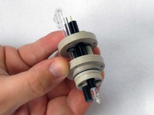
Figure 12. Slide the larger part of the cap kit onto the probes. Note: there is a directionality and the cap will only fit on in one orientation. Shown here is the cap kit with probes and O-rings installed, just before sealing the probes into the cap.

 
Install a screw to join the two cap halves. Loosely tighten one screw at a time to appropriately balance the cap seal. Note: it is useful to insert the cap kit with electrodes into the half cell at this stage, before completely tightening the three screws. This allows any displaced air or fluid in the half cell from becoming pressurized as the cap kit is pressed into place.

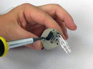
Figure 13. Install a screw to join the two cap halves. Loosely tighten one screw at a time to appropriately balance the cap seal. Note: it is useful to insert the cap kit with electrodes into the half cell at this stage, before completely tightening the three screws. This allows any displaced air or fluid in the half cell from becoming pressurized as the cap kit is pressed into place.

 
Once all three screws are loosely installed, slowly tighten each in a random order, watching the side of the cap to ensure pressure against the O-rings is applied evenly.

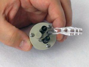
Figure 14. Once all three screws are loosely installed, slowly tighten each in a random order, watching the side of the cap to ensure pressure against the O-rings is applied evenly.

Back To Top
Questions? Find Answers.

Our knowledgebase is the central repository for written content, including help topics, theory, application notes, specifications, and software information.

Select a category below or view the Knowledgebase home page
Software

Detailed information about our Software, which includes AfterMath and retired PineChem.

Applications

Application notes discuss practical aspects of conducting specific experiments.

Theory

Fundamental electrochemical theory presented in a brief and targeted manner.

Product Specifications

Review complete product specifications and compare products within a category here.