1. Selecting an EIS Circuit
When performing an EIS Circuit Fit or Circuit Simulation in AfterMath Blue, the user has two options: (1) select a circuit from the set of Built-In Circuits; or (2) construct a User-Defined Circuit. Upon adding the new Circuit Fit or Circuit Simulation node, the Circuit Library window will appear, as shown below:
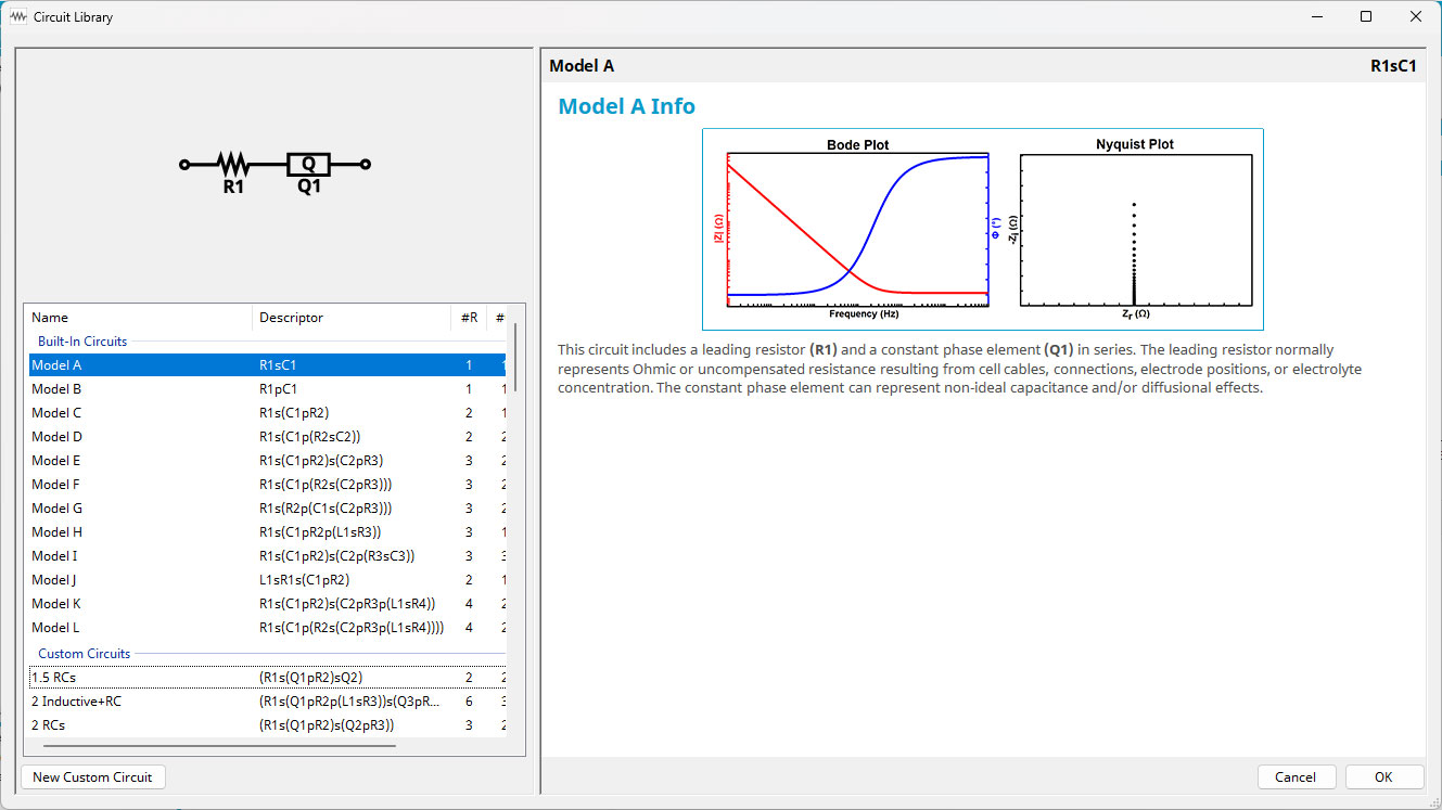
EIS Circuit Library in AfterMath Blue
Any previously-saved User-Defined Circuits will appear in the bottom section and may be selected again. Double-clicking on any circuit in either list will select that circuit for fitting or simulation.
2. User-Defined Circuits: GUI
The most common method of constructing a new User-Defined Circuit is by clicking “New Custom Circuit,” then using the graphical user interface (GUI) in the circuit designer window that appears, as shown below:
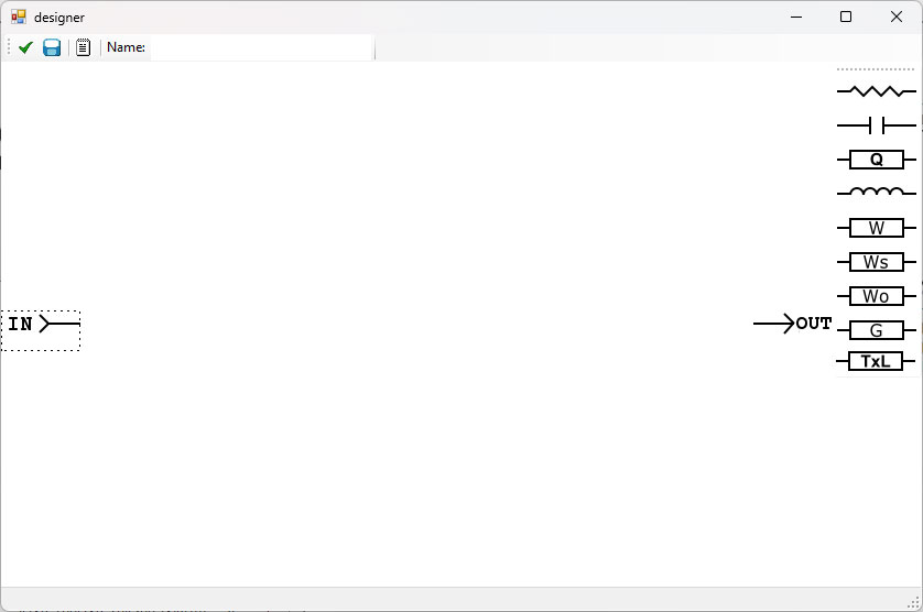
AfterMath Blue Circuit Designer Window
Circuit elements can be dragged-and-dropped from the right side into the blank space, then the left and right terminals connected as desired to form a custom circuit, as shown below:
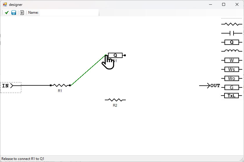
Drawing Custom Circuits with AfterMath Blue Circuit Designer GUI
Once the circuit has been drawn and all terminals connected as desired, it is good practice to verify the circuit is valid. The checkbox at the top left of the designer window can be clicked, and AfterMath Blue will indicate whether the circuit is valid (first figure below) or invalid (second figure below), including what issues must be rectified.
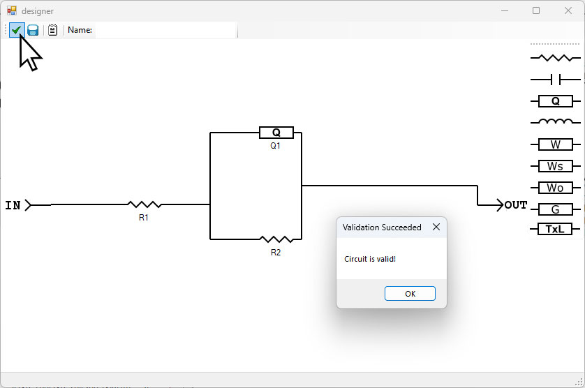
AfterMath Blue Custom Circuit Validation Check with Valid Circuit
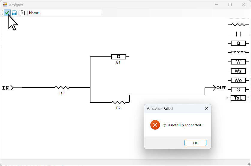
AfterMath Blue Custom Circuit Validation Check with Invalid Circuit
If the circuit is valid, it can be saved. A name must be given in the box at the top labeled “Name:,” then the save icon can be clicked, as shown below:
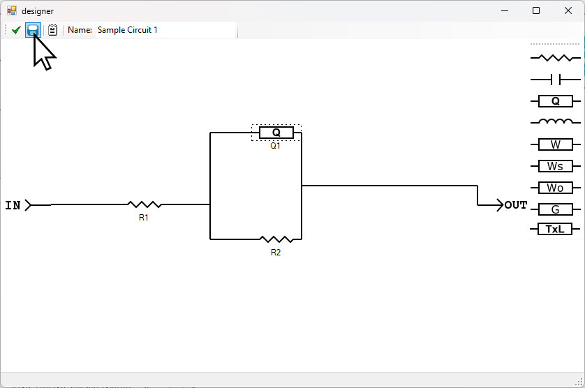
Saving Custom Circuits in AfterMath Blue
After saving the circuit, the X in the upper right of the designer window can be clicked, and then the custom circuit will be visible in the list of User-Defined Circuits, as shown below. This circuit can now be selected for fitting or simulation.
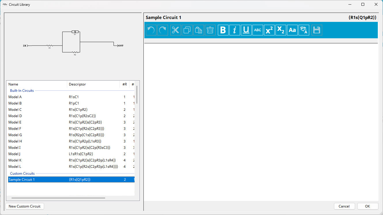
Circuit Library with Saved Custom Circuit
3. User-Defined Circuits: Descriptor Entry and Syntax
An alternate way to create a User-Defined Circuit is by using the notepad icon at the top of the designer window. When this icon is clicked, a Descriptor Entry window appears. In this window, a circuit can be added manually by typing in the appropriate syntax (see below).
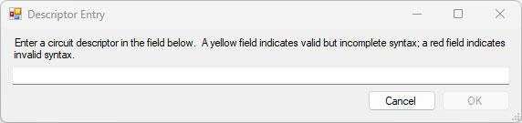
AfterMath Blue EIS Circuit Descriptor Entry Syntax Window
Each circuit in the AfterMath Blue Circuit Library, whether Built-In or User-Defined, has both a Descriptor and a Name. These fields cannot be changed for the Built-In Circuits. When creating a User-Defined Circuit using the GUI, a unique name must be given to save the circuit into the library, as shown previously. Additionally, a Descriptor will be automatically generated from the drawn circuit.
When entering a circuit descriptor to create a custom circuit, the proper syntax must be used. The Descriptor Entry will alert the user while typing a circuit whether the circuit syntax is valid but incomplete (yellow), or invalid (red). Below are the rules for circuit syntax in AfterMath Blue:
All circuit elements are accompanied by a number, and all elements must have a distinct name. For example, “R1”, “R2”, and “R3”. It is also not required to start at the index of 1 for each element. Additionally, once any custom circuit has been created, whether via the Descriptor Entry box or the GUI, any individual circuit element can be renamed as desired.
