1. Introduction
When performing electrochemical experiments in non-aqueous media, finding the ideal reference electrode can be challenging. Here, we will describe constructing and using such a non-aqueous reference electrode. We offer kits, based on silver electrode materials, in which users can develop their own non-aqueous reference electrode.
2. Reference Electrode Stability
A good and dependable reference electrode provides a stable potential and is not prone to environmental factors. Ideal reference electrodes have the following characteristics:
- A reversible reference redox pair (fast electron transfer rate)
- Good contact between the redox pair
- A stable liquid junction potential that is unaffected by temperature or local chemical composition around the frit
In practice, all reference electrodes have unstable liquid junction potentials that are affected by temperature and local chemical composition near the frit. For example, the silver chloride reference electrode, whose shorthand electrochemical reaction is written as Ag|AgCl|KCl (saturated), is the most widely used practical reference electrode. It is as stable and reliable as the saturated calomel reference electrode (SCE, whose shorthand electrochemical reaction is written as Hg|Hg2Cl2|KCl (saturated), but not as toxic. Ag/AgCl and SCE reference electrodes suffer only from an unstable liquid junction potential affected by temperature and local chemical composition near the frit. In aqueous solutions, changes in the liquid junction potential produce a drift on the order of few millivolts over a period of one year because of the high K+ and Cl– concentrations; however, when switching to non-aqueous systems, the liquid junction potential can be rather large. At the interface of two solvents, for example at the aqueous|non-aqueous interface or the interface of two different non-aqueous solvents, it can be hundreds of millivolts.
Poor contact between redox pairs can manifest itself in many ways; small electrode area diminishes contact, contact between redox pairs in different phases reduces contact (solid-solid contact has a larger effective contact area than solid-ion contact), and unstable local concentrations of one or both species reduces contact.
3. Modification for Non-Aqueous Reference Electrodes
When the stable Ag/AgCl reference electrode is used for non-aqueous systems, the electrolyte inside the Ag/AgCl reference electrode compartment (saturated KCl in water or a polar organic solvent) is often different than the main electrolyte (a salt in non-aqueous solvent). Since the reference electrode is placed in close proximity to the working electrode to reduce Ohmic drop, any leakage or mixing of the two electrolytes causes an unwanted response at the working electrode. Therefore, to avoid contamination of the main electrolyte by the reference electrolyte, a frit is used; frits slow down electrolyte mixing times. Even with the use of a frit, reference electrodes used for non-aqueous systems may encounter the following problems:
- Contamination of the external electrolyte with water, the filling solution solvent. Despite using a frit, it is still possible for internal reference electrode filling solution to diffuse to the external electrolyte solution.
- Frit pore plugging. Due to the insolubility of KCl in organic solvents, plugged pores are a common reference electrode problem. The use of a reference electrode with plugged pores will often cause potentiostat issues. For example, plugged pores allow external electromagnetic fields to cause interference, resulting in noisy data. In other words, the impedance (across the frit interface) of the reference electrode increases when pores are plugged. In extreme cases, a completely blocked reference electrode will result in the loss of potentiostat control because it loses its reference point.
- Reference electrode potential drift due to the liquid junction potential across the frit interface.
To alleviate the effects of these common problems, several methods have been proposed, each of which has its own shortcomings (see Table 1).
To illustrate, a silver/silver nitrate reference electrode, whose shorthand reaction is written as Ag|AgNO3 in CH3CN (10 mM)|frit, can be used as an alternative redox pair reference electrode. The silver/silver nitrate redox couple is similar to a primary redox standard; however, the silver/silver nitrate reference electrode suffers from certain instabilities. For example, in the presence of oxygen, Ag2O forms and disrupts the Ag/Ag+ redox pair, and Ag+ can leak into the main chamber, affecting the electrochemistry that a researcher is investigating.
Secondly, one can combine the silver/silver nitrate reference electrode with a double junction (or salt bridge) to minimize Ag+ leakage, but an increase in electrode impedance will result, possibly leading to reference electrode instability over time.
The third modification, a pseudo reference electrode, consists of a pure, freshly polished silver wire. The silver pseudo reference electrode functions because a natural oxide layer forms on the silver wire, creating a redox reaction whose shorthand notation is Ag|Ag2O|frit. As alluded to above, the silver/silver oxide pseudo reference electrode does not have a stable and reproducible redox potential and must therefore be calibrated using an internal standard. Ferrocene is one of the most common internal standards due to its solubility in non-aqueous solvents as well as its highly reversible and well-behaved kinetics. Users will often add solid ferrocene to their electrochemical cell and find the potential at which its redox character is clearly observed. Then, all other measurements are made vs. ferrocene (whose redox potential is known and reported in the literature). Of note, if ferrocene redox peaks overlap with the analyte redox peaks, a different internal standard must be used. Additionally, changes in the chemical composition of the main electrolyte may occur as electrochemical reactions occur, causing a reference potential drift. To prevent this potential drift, it is important to isolate the silver wire with a fritted tube.
4. Non-Aqueous Reference Electrode Kits
This application will focus on reference electrodes created using a silver wire. Pine Research offers Ag pseudo reference electrodes, standard size (9.5 mm OD, see Figure 1) and LowProfile size (3.5 mm OD, see Figure 2). The following discussion applies to the both electrode sizes and the following list describes the features of either size:
- A glass tube with a mounted frit
- A silver wire
- An air-tight way to mount the silver wire
- Electrolyte solution
Once the frit has made contact with electrolyte solution, it must remain in contact with electrolyte solution at all times. DO NOT let the frit become dry, as the electrolyte salt will crystallize inside it and crack the frit, rendering it leaky and useless.
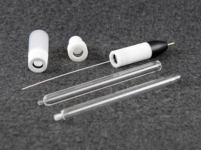
Figure 1: Standard Size (9 mm OD) Ag Non-Aqueous Reference Electrode Kit
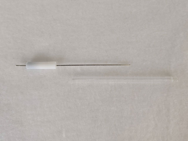
Figure 2: LowProfile Ag Non-Aqueous Reference Electrode Kit
During the course of an electrochemical experiment, electrogenerated products can deposit on the reference electrode frit. Allowing the frit to soak in electrolyte solution after an experiment serves to clean the frit. When the fritted glass tube is removed at a later time for another experiment, be sure to replace the solution inside the fritted glass tube as well as the solution inside the sealable container. Doing these two things will keep the frit clean and prevent unwanted, previous electrogenerated products from entering the electrochemical experiment.
5. Non-Aqueous Reference Electrode Study
This application looks to explore the stability across non-aqueous reference electrodes with varying frit composition, glass tube size disparity, and electrolyte filling solution. Specifically, two reference electrodes have been reviewed and discussed in this document: (A) LowProfile Glass Frit Ag Pseudo Reference Electrode (Part Numbers LowProfile Glass Frit Ag Pseudo Reference Electrode (93 mm) and LowProfile Glass Frit Ag Pseudo Reference Electrode (62 mm)); (B) Standard Size Ag Pseudo Reference Electrode with ceramic frit (Part Number AKREF0033). Several variations of electrode and filling solutions have been investigated and reported in this document (see Table 2).
5.1. Open Circuit Potential Study
With an open circuit potential (OCP) test, the stability of one reference electrode can be measured against another reference electrode. It is well-known that the Ag|AgCl|KCl (saturated)|frit reference electrode has a very stable redox potential in polar solvents like acetonitrile; that is, OCP does not vary with time. To test the stability of the reference electrodes constructed in Table 2, the Ag|AgCl|KCl (saturated)|frit reference electrode will be considered a master electrode to which the other potentials can be referenced; thus, if any variation is seen in a test reference electrode OCP, it can be contributed solely to the instability within the test reference electrode. It is interesting to note that if the solvent polarity is lowered, a high liquid junction potential drift will form at the aqueous/non-aqueous interface, rendering the Ag|AgCl|KCl (saturated)|frit reference electrode redox potential unstable; therefore, only reference electrodes that utilize acetonitrile for both the bulk electrolyte solvent and reference electrode solvent (A1, B1, and Pseudo1) can be compared to the stable Ag|AgCl|KCl (saturated)|frit reference electrode in this manner to determine their stability (see Table 2).
When OCP of reference electrodes A1, B1, and C1 are measured against the Ag|AgCl|KCl (saturated)|frit reference electrode, it is found that all three exhibit stable potentials with a drift rate of less than 0.3 mV/min (see Figure 3). For the different frits tested herein (mini-ceramic, fine glass, or ceramic), there is no significant impact on the stability of the reference electrode.
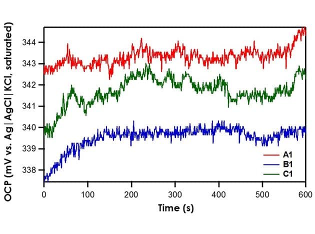
Figure 3. Relative Stability of Reference Electrodes A1, B1, and C1 with respect to the Ag|AgCl|KCl (saturated)|frit.
Recall that the shorthand for A1, B1, and C1 is Ag|AgNO3 in CH3CN (10 mM)|frit. The literature value for Ag|AgNO3 in CH3CN (10 mM)|frit vs. Ag|AgCl|KCl (saturated)|frit is 345 mV. All three reference electrodes are within ± 10 mV of the literature value, indicating that all three are stable reference electrodes. The Pseudo1 reference electrode has shorthand notation Ag|Ag2O|frit. Recall that the silver/silver oxide reaction does not have a stable redox potential; therefore, when the OCP of Pseudo1 is measured against the Ag|AgCl|KCl (saturated)|frit reference electrode, large potential drifts are initially seen (~5 mV/min) until OCP stabilizes (see Figure 4). Therefore, it is imperative to allow pseudo reference electrodes equilibrate in solution for at least an hour before use.
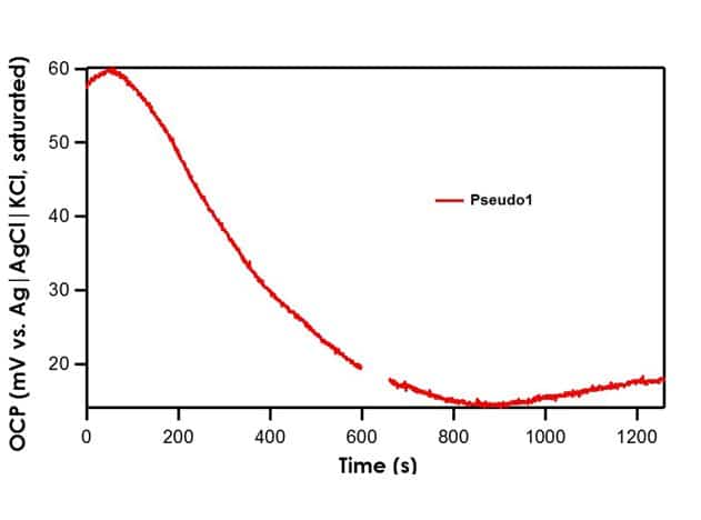
Figure 4. Relative Stability of Pseudo1 Reference Electrode with respect to the Ag|AgCl|KCl (saturated)|frit
5.2. Cyclic Voltammetry Study
OCP tests operate under a key assumption: the potential of one of the reference electrodes does not drift. Therefore, while it is possible to establish relative stability between two reference electrodes with an OCP test, it is not possible to tell if both electrodes are drifting at the same rate. A cyclic voltammetry (CV) test using ferrocene compliments OCP tests. Ferrocene undergoes a reversible, one electron oxidation to form ferrocenium

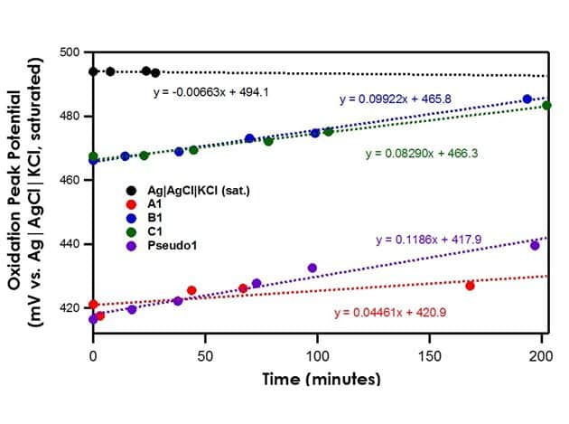
Figure 5. Oxidation Peak Position of Ferrocene with Varying Reference Electrodes in Acetonitrile
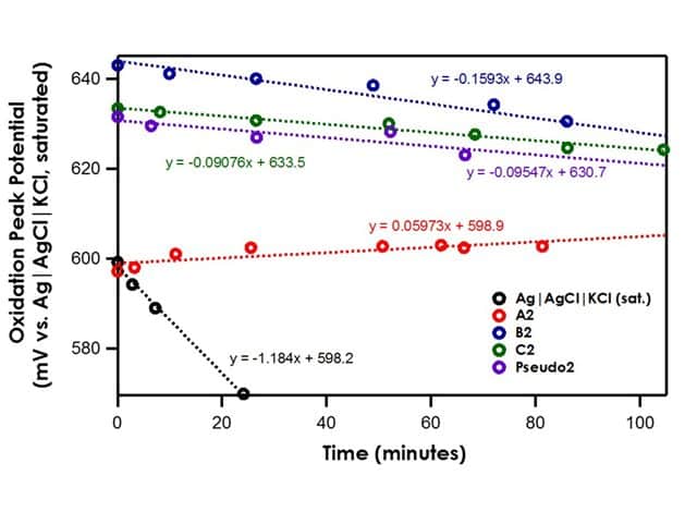
Figure 6: Oxidation Peak Position of Ferrocene with Varying Reference Electrodes in Dichloromethane
6. Conclusion
While large drifts (1 mV/min) are certainly due to the instability of a reference electrode, the origin of small drifts (less than 0.2 mV/min) observed in both acetonitrile and dichloromethane is not clear. It cannot be excluded that ferrocene redox chemistry undergoes subtle changes as repetitive CV scans are performed. In other words, the drift could be due to a shift in the oxidation potential caused by changes in surface electrochemistry or the surface state of the electrode. In addition, the oxidation product ferrocenium is less stable in organic solvent; a thin film of ferrocenium side reaction products can block the electrode surface, causing changes to the peak position.
The most stable non-aqueous reference electrode is Ag|AgNO3 (10 mM) in 100 mM NBu4PF6 in CH3CN|frit with a drift rate of less than 0.1 mV/s. It is recommended that a non-aqueous reference electrode be calibrated daily using a known redox pair such as ferrocene in a standard solution (1-5 mM ferrocene in 100 mM NBu4PF6 in CH3CN). While the silver/silver nitrate reference electrode is the most stable, researchers must exercise caution when using it. Since silver ions are soluble in acetonitrile, they can pass through the frit and contaminate the bulk solution. To minimize silver ion leakage, a double junction can be used. Nevertheless, in certain applications like the study of hydrogen evolution catalysis, even a small amount of silver ion contamination shifts the acid reduction potential, convoluting data obtained for the catalyst of interest1-2. In these instances, it is better to use a pseudo reference electrode. A pseudo reference electrode will not contaminate the bulk electrolyte solution. It does, however, experience greater potential drift. To account for this, the pseudo reference electrode should be allowed to equilibrate for at least an hour before use and referenced to an internal standard like ferrocene. If possible, the redox peaks of ferrocene should be included on each cyclic voltammogram taken, or measured directly after a linear sweep experiment.
7. References
- Pavlishchuk, V. V. ; Addison, A. W. Conversion constants for redox potentials measured versus different reference electrodes in acetonitrile solutions at 25°C. Inorg. Chim. Acta, 2000, 298(1), 97-102.
- McCarthy, B. D.; Martin, D. J.; Rountree, E. S.; Ullman, A. C.; Dempsey, J. L. Electrochemical Reduction of Brønsted Acids by Glassy Carbon in Acetonitrile—Implications for Electrocatalytic Hydrogen Evolution. Inorg. Chem., 2014, 53(16), 8350–8361.
