1. Introduction
The compliance voltage supplies the extra potential needed to drive the potentiostat to the desired potential.
Let’s review two potentiostat fundamentals.
- The potential is measured between the working and reference electrode.
- The current is driven between the counter and working electrode.
When the potential between the working electrode and reference electrode changes, it is the result of current that flows between the counter and working electrode. To drive current, a voltage must be applied between the counter and working electrode. The compliance voltage is the maximum voltage that can be applied between the counter and working electrode (see Figure 1).
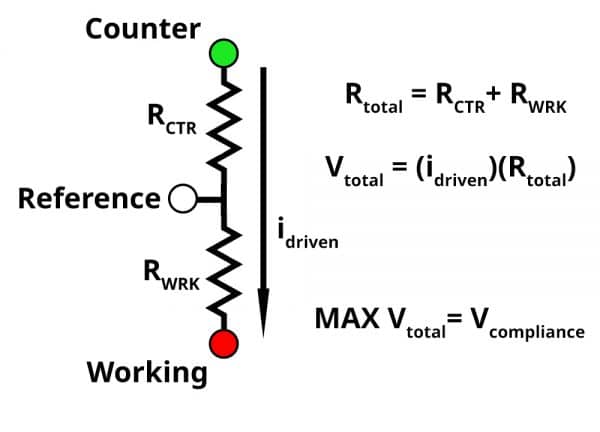
Figure 1: Diagram of electrode leads that connect to your potentiostat; GREEN is counter, WHITE is reference, and RED is working. RCTR represent the resistive elements between the reference and counter electrode. RWRK represent the resistive elements between the reference and working electrode.
The green, white, and red circles represent the counter, reference, and working electrode leads of your potentiostat respectively. RCTR represents resistive elements between the counter and reference electrode, and RWRK represents resistive elements between the working and reference electrode. The resistive elements can vary depending on your electrochemical system. For example, in solution phase electrochemistry, the RWRK consists of the double layer capacitance, charge transfer resistance, and uncompensated solution resistance. If your solution is highly resistive, the potentiostat must apply a higher voltage (equal to the iR drop in solution) to create the desired potential difference between the working and reference electrode.
If RWRK is 1 kΩ, applying 1 V between the working and reference electrode (red and white leads) would result in a measured current of 1 mA based on Ohm’s law. If RCTR is 1 kΩ, there is now two 1 kΩ resistors in series between the counter and the working electrode. To achieve the measured current of 1 mA, the potential between the counter and working electrode must be 2 V. An additional 1 V is needed to meet the measured result of 1 mA. The maximum voltage (MAX Vtotal) a potentiostat can supply to meet the desired potential and current response is the compliance voltage. It should be noted that when working in a two-electrode configuration, the compliance voltage is no longer an issue. The counter and reference electrode are shorted in the two-electrode configuration, which bypasses RCTR in figure 1.
A chemical system where the potentiostat operates normally may suddenly result in a compliance voltage error if the measured current doubles. In figure 1, if the measured current doubles, then the voltage also doubles (from the iR drop). This also applies to an increase in resistance (RCTR). It’s not uncommon that the addition of a membrane or fritted tube to separate the counter and working electrode results in a compliance voltage issue for an otherwise normal electrochemical system.
2. Troubleshooting compliance voltage
Depending on the electrochemical system, researchers can implement several options to fix a compliance voltage issue. The next few sections will go over how to identify a compliance voltage issue and a few solutions researchers can try to over come it. It is important to note that the compliance voltage is a specification that is limited by the potentiostat. A researcher may need to purchase a new potentiostat with a higher compliance voltage.
2.1. How to spot a compliance voltage issue
Researchers can identify a compliance voltage issue if the applied potential is never reached during an experiment. In figure 2, the cyclic voltammogram was swept between +4 and -4 V. However the potential only reaches ~ +2 and -2 V, as indicated by the black circles.
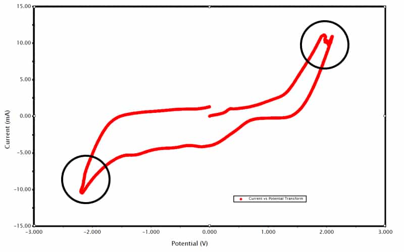
Figure 2: Cyclic voltammogram of Tylenol where the voltage is swept between -4 to 4 V.
A compliance voltage issue becomes apparent when looking at the applied potential waveform. In figure 3, the orange trace represents the applied potential waveform entered by the user. The red trace, however, is the actual potential waveform applied by the potentiostat.

Figure 3: Potential waveform for cyclic voltammogram. Orange is applied, Red is actual.
At the beginning of the waveform (time = 0 seconds) the orange and red trace overlap each other. However, when the voltage reaches +2 V, the red trace flattens out, and is unable to reach the desired potential of +4 V. The same behavior can be seen at -2 V when the red trace flattens and is unable to reach -4 V with the orange trace. This kind of behavior in the potential waveform is symptomatic of a compliance voltage issue.
2.2. Suggestions for troubleshooting compliance voltage issues
We understand that troubleshooting a compliance voltage issue is dependent on the electrochemical system. Below is a list of suggestions for troubleshooting a compliance voltage issue.
- If the counter electrode is in a fritted isolation tube, removing the isolation tube can help overcome the compliance voltage. This is only a solution if the counter and working electrode don’t need to be separated.
- A small counter electrode can make it difficult to drive current to the working electrode. This can result in a compliance voltage issue as the potentiostat will increase the voltage to drive my current. Increasing the size of the counter electrode can alleviate this issue.
- There must be charge balance between the working and counter electrode. The potentiostat will attempt to increase the voltage at the counter electrode if insufficient current is generated at the counter electrode compared to the working electrode. The addition of a sacrificial redox molecule that is easily oxidized or reduced, (depending on the working electrode reaction) for the counter electrode to electrolyze can prevent a compliance voltage issue.
- If the electrochemical system or it’s conditions cannot be changed, then the only solution is to purchase a new potentiostat with a higher compliance voltage.
