 This article is adapted from Section 2 of the User Manual for the Pine Modulated Speed Rotator (MSR).
Related Links: MSR User Manual, MSR Rotator Support Page, Pine Research Instrumentation
[/call_to_action]Table of Contents
Section 2 – Description
The MSR rotator provides excellent steady-state control of constant rotation rates, but it also offers outstanding acceleration/deceleration control for those applications where the rotation rate must be modulated. The base rotation rate (for steady-state constant rate control) may be manually adjusted from to
by turning a ten-turn potentiometer knob located on the front panel of the control unit. As the knob is turned, a built-in tachometer measures the actual rotation rate, and this rate is continuously displayed on the front panel of the control unit. Manually turning the knob and observing the rotation rate is by far the most common manner in which the rotation rate is selected.
More complex control of the rotation rate is possible when the MSR rotator is connected to a potentiostat system capable of supplying an analog rotation rate signal. While specific details vary from one system to another, the basic idea is that the potentiostat produces an analog signal that is proportional to the target rotation rate. This analog signal is carried by a cable (supplied by the potentiostat manufacturer) to a pair of input banana jacks on the front panel of the rotator’s control unit. This connection permits the software which controls the potentiostat to control the rotation rate using a constant voltage level (for steady-state rotation) or a more complex waveform such as a sine wave (for hydrodynamically modulated voltammetry).
The rotator is able to accurately follow complex waveforms and create the desired rotation rate response by using a high rate, low inertia, permanent magnet DC motor in combination with a high voltage, bi-polar power supply. In general, the MSR can track and follow low frequency (less than ) external input signals with amplitudes that do not exceed
of the baseline rotation rate. The usual proportionality between the external input signal and the rotation rate is
, but a hardware jumper setting inside the control unit may be used to select the different ratios (see Section 6.7).
The rotation rate is typically monitored by observing the front panel display on the control unit. In addition, the tachometer measurement can be monitored by connecting an oscilloscope, voltmeter, or other recording device across the two output banana jacks on the front panel. The voltage signal from the tachometer presented at these output jacks is proportional to the rotation rate. The ratio used for this signal is .
The control unit is connected to the motor unit using a 15-conductor cable with “straight thru” wiring terminated on each end with HD-15 connectors.The usual cable length is (
), but longer distances can be spanned by chaining together multiple cables.
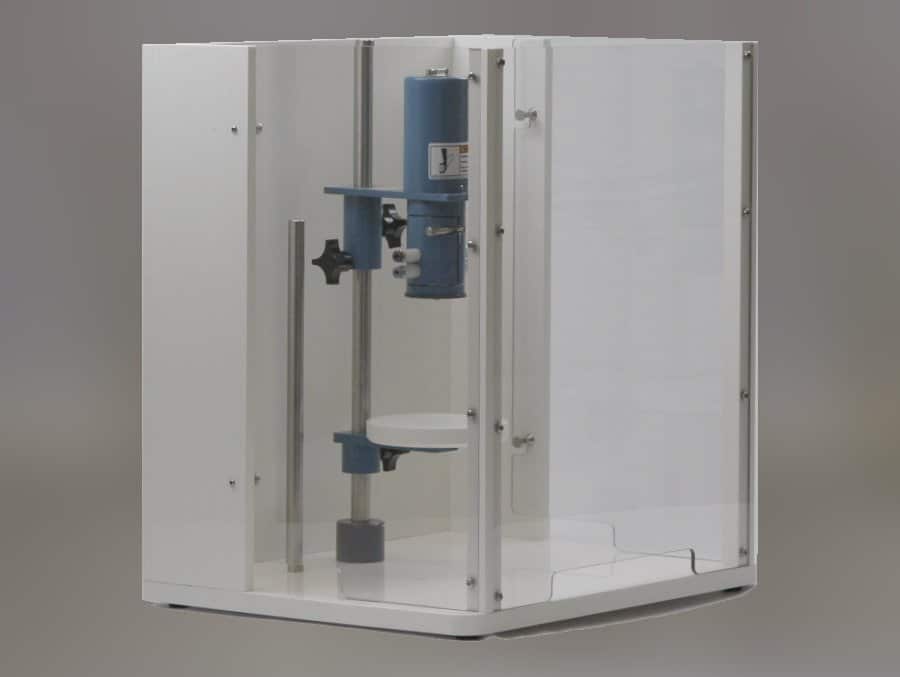
The motor unit can be positioned vertically along a center post that is mounted in a sturdy and chemically resistant enclosure base. A flat cell platform can also be positioned along the center post, making it easy to raise and lower the cell with respect to the motor unit. The electrochemical cell can be further secured by clamping it to a side post located adjacent to the center post.
[call_to_action]Rotating shaft.
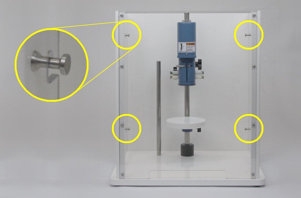
Do not turn on the rotator or rotate the electrode shaft unless the enclosure window is secured to all four pins as shown below.
Use extreme caution when operating the rotator at rotation rates above
AVERTISSEMENT:
Arbre en rotation.
Ne mettez pas le rotateur en marche et ne marche ni l’arbre de l’électrode en rotation si la fenêtre du boîtier n’est pas fermée à l’aide des quatre broches tel qu’indiqué ci-dessous.
Soyez extrêmement prudent lorsque vous utilisez le rotateur à des vitesses de rotation supérieures à .
The motor unit and electrochemical cell are enclosed on the back side by a rear wall permanently attached to the enclosure base. The cell and motor are further enclosed on the front side by a transparent enclosure window. The enclosure window can be removed to set up the cell, but the enclosure window must be securely mounted to the enclosure base before rotating the electrode.
The rotator may be used with rotating disk electrodes (RDEs), rotating ring-disk electrodes (RRDEs), and rotating cylinder electrodes (RCEs). Connections to the rotating electrode shaft are made by two pairs of silver-carbon brushes. For RDEs and RCEs, all four brushes make contact with the rotating shaft and may be shorted together to obtain four points of contact. For RRDEs, the upper brush pair contacts the disk electrode, and the lower pair contacts the ring electrode.
2.1 Major System Components
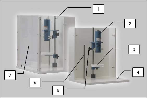
The table and photo below (see Figure 2.1) show the major system components.
1. Center Post – The cell platform, support collar, and motor unit are supported by the center post.
2. Motor Unit – The motor unit is mounted on the center post and holds the motor and brushes.
3. Cell Platform – The cell platform supports cells with flat bottom surfaces.
4. Enclosure Base – The support frame is fabricated from a chemically-resistant polymer.
5. Support Collar – The support collar helps prevent motor from unexpectedly sliding down center post.
6. Side Post – The side post is a support for cell clamps and can be installed in one of two positions.
7. Enclosure Window – This is a transparent window covering the front of the overall enclosure.
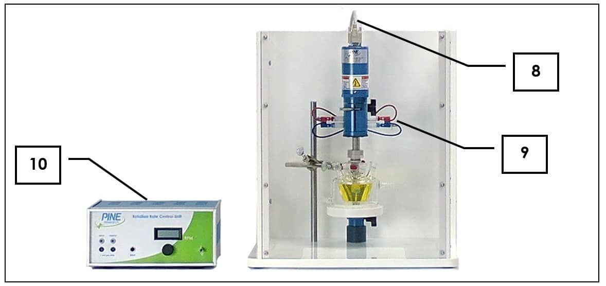
8. Motor Control Cable – This cable connects the control unit to the motor unit.
9. Banana Cables (red and blue) – The upper pair of brush contacts (red) is used with rotating disk electrodes (RDE) and rotating cylinder electrodes (RCE). The lower pair of brush contacts (blue) is only used with rotating ring-disk electrodes (RRDE), in which case the lower pair of brushes contact the ring while the upper pair of brushes contact the disk.
10. Control Unit – The control unit contains the power supply and rotation rate control circuitry.
2.2 Enclosure Variations
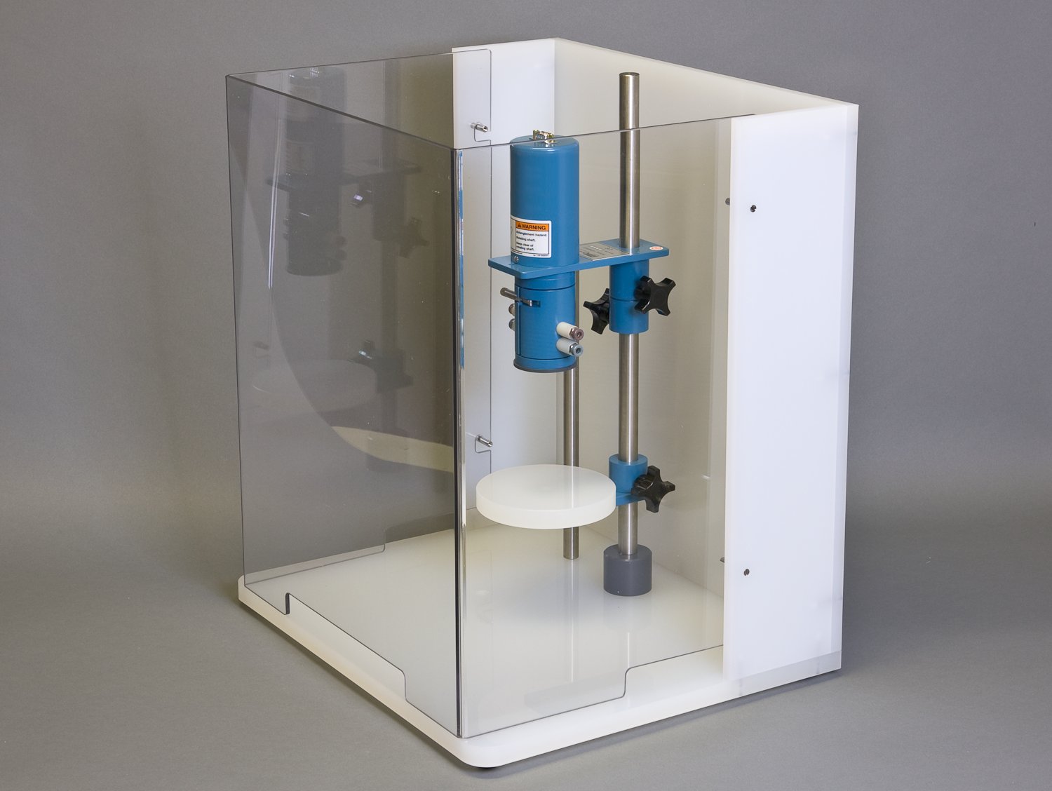
The enclosure consists of the enclosure base (fabricated from an opaque white polymer) and an enclosure window (transparent). The enclosure window may be a single pane (see Figure 2.2, left) or it may be assembled from three separate panes (see Figure 2.2, right).
Figure 2.2: Two Styles of Enclosure Window
There are four hooks on the enclosure window which are secured to four anchor pins on the enclosure base. There are three styles of anchor pins.
Figure 2.3: Three Styles of Anchor Pins
The anchor pins may be simple straight pins (see Figure 2.3, left), or they may combine a pin with a rubber bumper (see Figure 2.3, middle), or they may be tapered pins (see Figure 2.3, right).
2.3 Control Unit Components
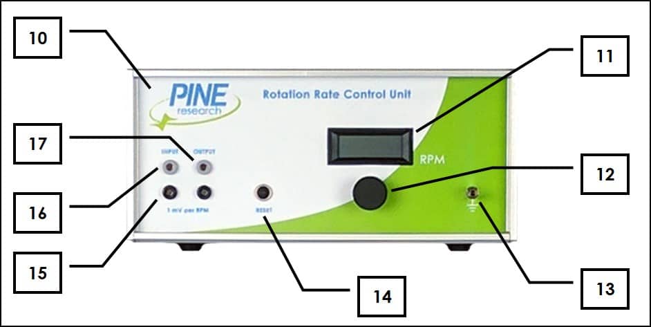
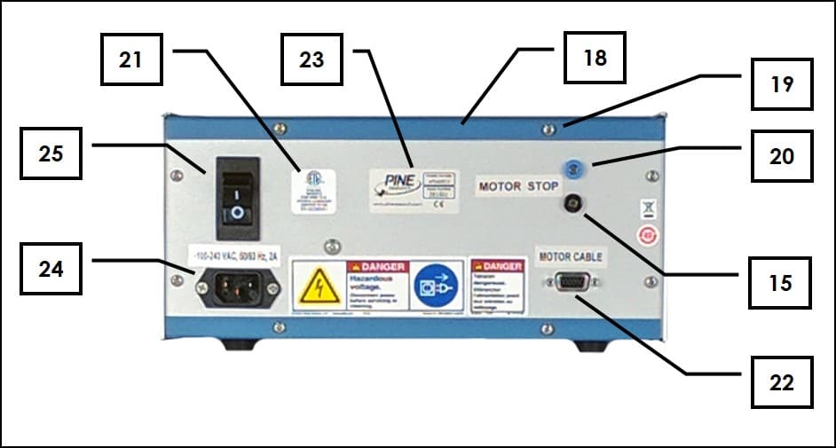
The tables and photos below (see Figure 2.4) show the control unit components.
10. Control Unit – The control unit contains the power supply and rotation rate control circuitry.
11. Rotation Rate Display – 4 ½ digit display of rotation rate ()
12. Rotation Rate Knob – 10 turn knob for manual rotation rate control
13. 
14. Reset Button – Motor circuit breaker reset
15. Signal Ground – DC signal common (isolated from chassis)
16. Rotation Rate Input Signal – External control of the rotation rate is possible by applying a voltage signal across these banana jacks (see Section 4.7.3). (, or
ratio,
impedance)
17. Rotation Rate Output Signal – A voltage signal proportional to the rotation rate is presented at these banana jacks. (,
output impedance)
18. Control Box Cover – Metal cover
19. Control Box Cover Screws – Metal screws that hold cover on control unit
20. Motor Stop Input Signal – This digital logic signal is used to stop electrode rotation (see Section 4.6.4).
21. NRTL Mark – Nationally Recognized Testing Laboratory compliance label (ETL Mark from Intertek)
22. Motor Cable Connector – Accepts one end of motor control cable
23. Serial Number Plate – Unique system serial number
24. Power Cord Connector – Connects to external electrical power cord
25. Power Switch – Main power switch (with circuit breaker)
2.4 Motor Unit Components
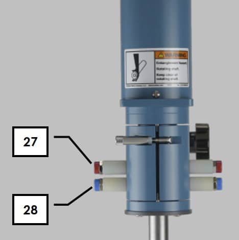
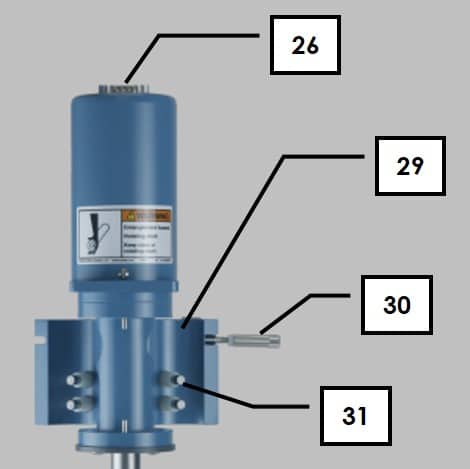
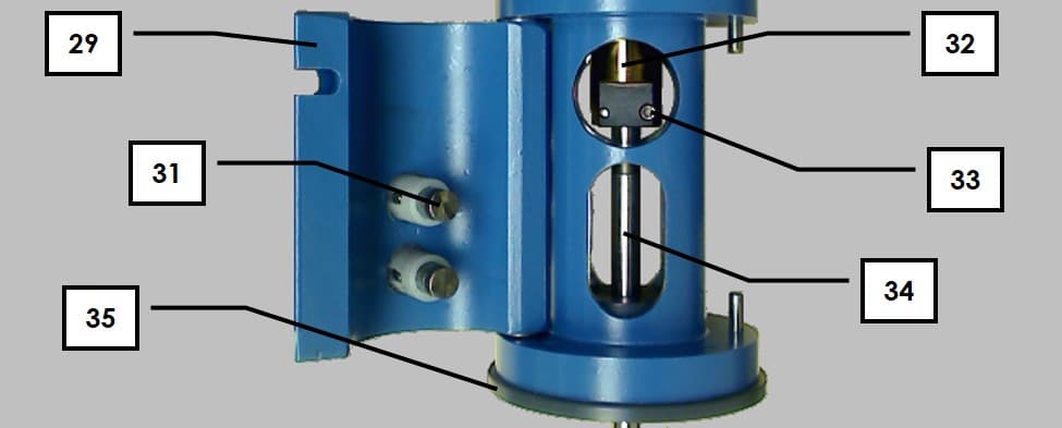
The table below and the photographs (see Figure 2.5) identify the major components of the motor unit.
26. Motor Cable Connector – Accepts one end of motor control cable
27. Upper Brush Pair (red) – These upper brushes make contact on opposing sides of the rotating shaft and are used to make contact with rotating disk electrodes and rotating cylinder electrodes.
28. Lower Brush Pair (blue) – These lower brushes make contact on opposing sides of the rotating shaft and are used to make contact with the ring electrode when working with rotating ring-disk electrodes.
29. Clamshell Doors – These doors open to permit access to the brush chamber
30. Door Latch – Secures clamshell doors in closed position
31. Brush Contact – Spring-loaded silver-carbon brush provides electrical contact with the rotating shaft
32. Motor Coupling – Used to attach the shaft to the motor
33. Motor Coupling Hex Screw Pair – Hex screws located on either side of the motor coupling tighten to hold the shaft inside the motor coupling
34. Electrode Shaft – The top end of the rotating shaft is mounted in motor coupling and the active electrode surface is at the bottom end of the shaft.
35. Lower Bearing Assembly – An easily replaceable bearing assembly stabilizes the rotating shaft at the point where the shaft exits the motor unit. Metal and ceramic bearings are available.
2.5 Typical Rotating Disk Electrode Design
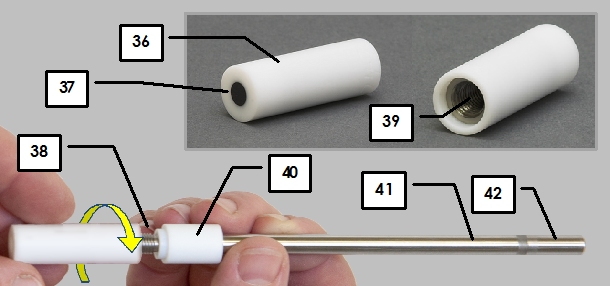
Most rotating disk electrodes consist of two parts (see Figure 2.6), a shaft and a tip, but in some cases the entire electrode may be a single piece.
36. Insulating Shroud on Tip – This insulating shroud material is typically a polymer such as PTFE, PEEK or PCTFE.
37. Electrode Surface – The electrode surface is typically polished to mirror smoothness.
38. Threads on shaft – These threads are normally in electrical contact with disk.
39. Threads inside tip – These threads are normally in electrical contact with disk.
40. Insulating Shroud on Shaft – This insulating shroud material is typically a polymer such as PTFE, PEEK or PCTFE.
41. Disk Contact Area – This metal area on the shaft is normally in electrical contact with disk.
42. Shaft Mounting Area – This electrically-isolated portion of the shaft is used to physically mount the shaft in the motor coupling.
2.6 Typical Rotating Ring-Disk Electrode Design
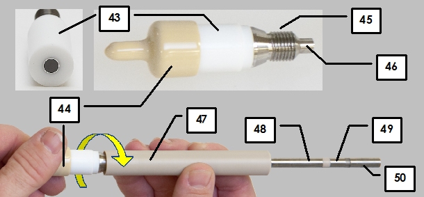
Rotating ring-disk electrode tips mount on to a special two-conductor shaft (see Figure 2.7). In some cases, the tip can be taken apart into smaller pieces.
43. Insulating Shroud on Tip – This insulating shroud material is typically a polymer such as PTFE, PEEK or PCTFE.
44. Plastic Cover – Cover protects electrode when not in use.
45. Ring Threads on Tip – These threads contact the ring electrode.
46. Disk Core on Tip – This disk core is in electrical contact with the surface of the disk electrode.
47. Insulating Shroud on Shaft – This insulating shroud material is typically a polymer such as PTFE, PEEK or PCTFE.
48. Ring Contact Area – This metal area on the shaft is normally in electrical contact with the ring electrode.
49. Disk Contact Area – This metal area on the shaft is normally in electrical contact with the disk electrode.
50. Shaft Mounting Area – This electrically-isolated portion of the shaft is used to physically mount the shaft in the motor coupling.

