
1. Technique Overview
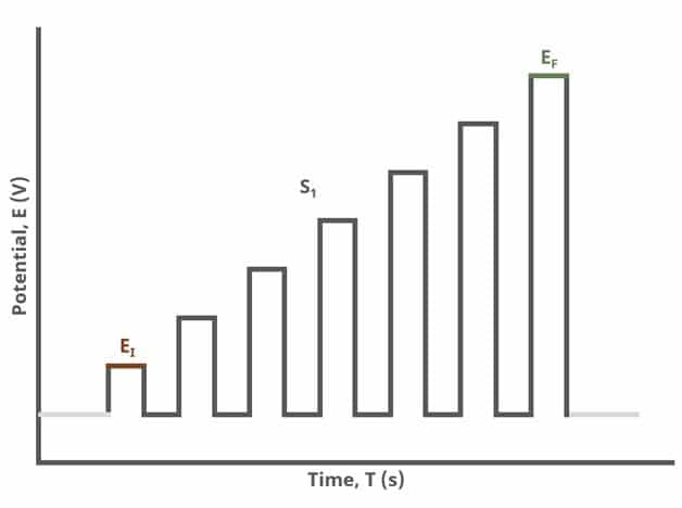
Figure 1: Normal Pulse Voltammetry (NPV) One Segment Waveform
 , which is determined as
 (5)
 is the pulse width and
 is the sampling width (see Table 1 and Figure 7).
When Segments (SN) = 2 (see Figure 2), increasing potential pulses step from a common baseline in a linear fashion, from an initial potential to vertex potential, at which time the NPV pulses decrease until reaching the final potential. Again, the current is sampled in the same fashion as NPV experiments with other Segment values.
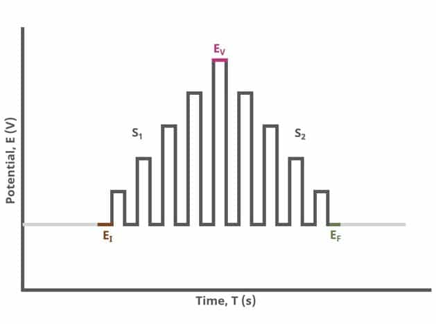
Figure 2: Normal Pulse Voltammetry (NPV) Two Segment Waveform
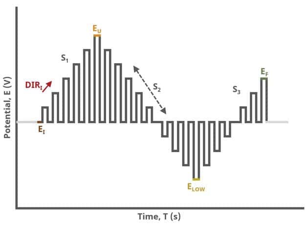
Figure 3: Normal Pulse Voltammetry (NPV) Three Segment Waveform
2. Fundamental Equations
 (6)
 is reduced in a one-electron reaction to
 with formal potential
 . The application of a baseline potential should be sufficiently positive of such that no faradaic current flows. After a period of time
 , typically 100 - 5000 ms, the potential of the working electrode is stepped to a more negative value for a period of time. The total time from the application of the baseline potential through the application of the potential pulse is
 .
The potential pulse is incrementally increased with each cycle. As the potential of the working electrode approaches faradaic current flows due to the reduction of to . Upon the application of the baseline potential in the next cycle, is oxidized back to . When the potential of the working electrode gets sufficiently negative of , is reduced to at a maximum rate and the current levels off to a plateau. The magnitude of this current plateau is given by
 (7)
 (8)
3. Experimental Setup in AfterMath
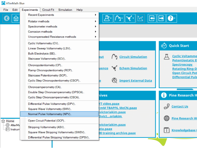
Figure 4: Normal Pulse Voltammetry (NPV) Experiment Menu Selection in AfterMath
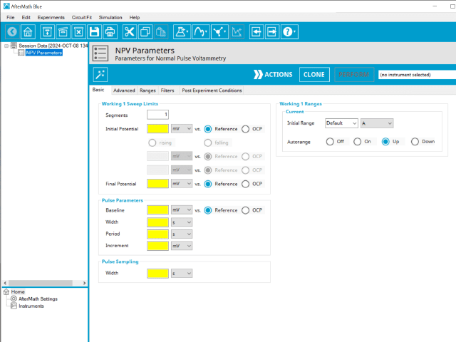
Figure 5: Normal Pulse Voltammetry (NPV) Experiment Parameters
Induction Period → Pulse Sequence → Relaxation Period → Post-Experiment Idle Conditions
Continue reading for detailed information about the fields on each unique tab.3.1. Basic Tab
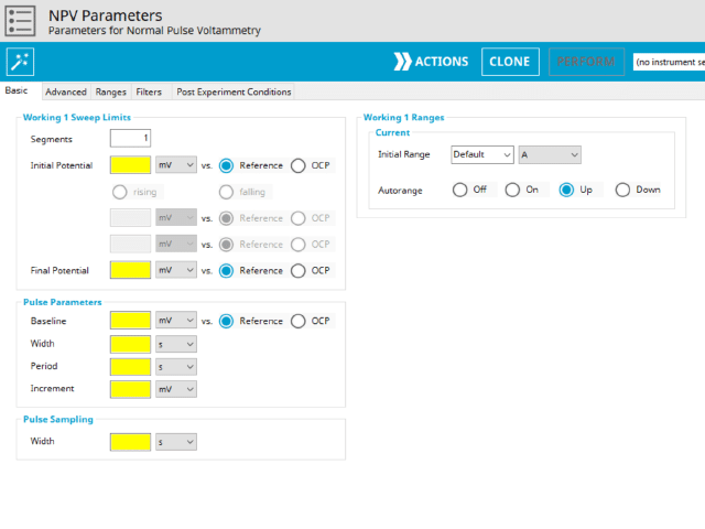
Figure 6: Normal Pulse Voltammetry (NPV) Basic tab in AfterMath
 ). Refer to Figures 1, 2, and 3 for examples of such NPV waveforms that vary based on number of segments.
The parameter settings for pulse-type experiments are often not as clear as with something more simple like Cyclic Voltammetry (a sweep method ). Refer to Figure 2 above when understanding each parameter of the NPV pulse. Further, clicking "AutoFill" ("I Feel Lucky" in older versions of AfterMath) provides reasonable starting parameters if you are unsure of typical values used in these experiments. Most often, research journal articles describe the NPV pulse sequence used, which can be replicated using AfterMath.
The experiment concludes with a relaxation period. During the relaxation period, a set of final conditions (specified on the Advanced tab) are applied to the electrochemical cell and the cell equilibrates at these conditions (set on the Advanced Tab). Data are not collected during the induction period, nor are they shown on the plot during this period.
At the end of the relaxation period, the post-experiment idle conditions are applied to the cell and the instrument returns to the idle state.
A plot of the typical experiment sequence, containing labels of the fields on the Basic tab, helps to illustrate the sequence of events in an NPV experiment (see Table 1 and Figure 7).


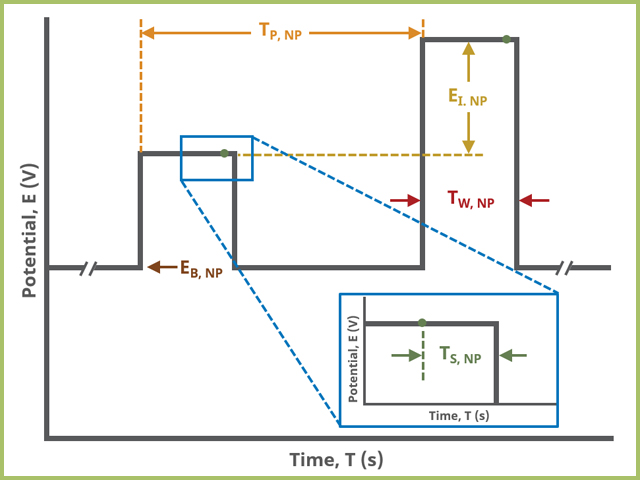
Figure 7: Normal Pulse Voltammetry (NPV) Pulse Parameter Field Diagram
3.2. Advanced Tab
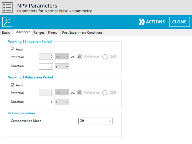
Figure 8: Normal Pulse Voltammetry (NPV) Experiment Advanced Tab in AfterMath
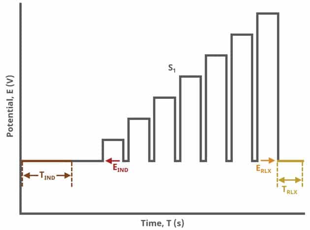
Figure 9. Normal Pulse Voltammetry (NPV) General Experiment Sequence in AfterMath
3.3. Range, Filters, and Post Experiment Conditions Tab
4. Sample Experiment
 show a sigmoid-shaped curve (see Figure 10). In this experiment, the specific parameters were as follows:
- 2 mm OD Pt WE
- Pt mesh CE
- Baseline Potential = 0.1 V
- Initial Potential = 0.25 V
- Final Potential = 1 V
- Pulse increment = 10 mV
- Pulse period = 100 ms
- Pulse width = 10 ms
- Sample width = 1 ms
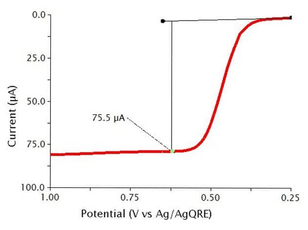
Figure 10. Typical NPV results for 0.5 mM Ferrocene in 0.1 M Bu4NClO4/MeCN
show a sigmoid-shaped curve (see Figure 11). In this experiment, the specific parameters were as follows:
- 2 mm OD Pt WE
- Pt mesh CE
- Baseline Potential = 1 V
- Initial Potential = 0.75 V
- Final Potential = 0 V
- Pulse increment = 10 mV
- Pulse period = 100 ms
- Pulse width = 10 ms
- Sample width = 1 ms
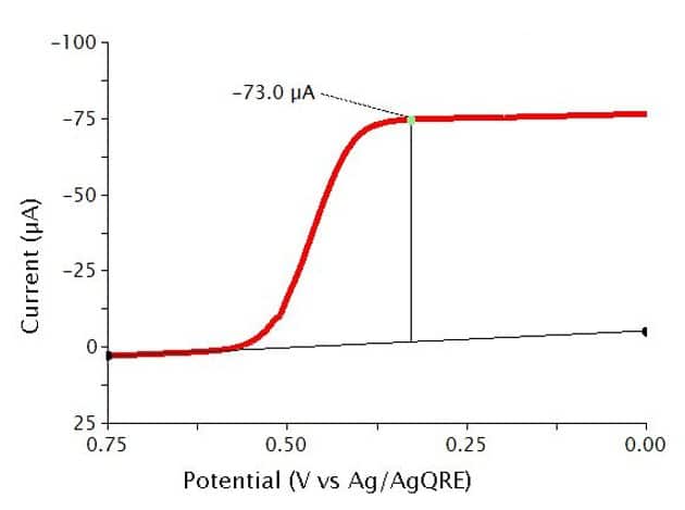
Figure 11: Typical RNPV results for 0.5 mM Ferrocene in 0.1 Bu4NClO4/MeCN
show two sigmoid-shaped curves (see Figure 12, same conditions as for those used in generating the data in Figure 11). Since Ferrocene is fully-reversible electrochemically, the two sigmoids overlap.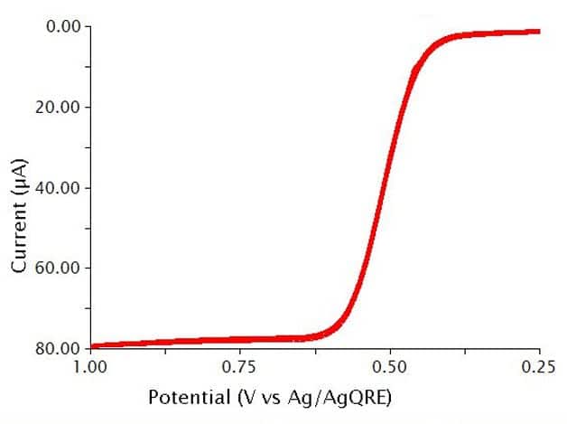
Figure 12. Typical CNPV results for 0.5 mM Ferrocene in 0.1 Bu4NClO4/MeCN
5. Example Applications
6. References
- Bard, A. J.; Faulkner, L. A.  Electrochemical Methods: Fundamentals and Applications, 2nd ed. Wiley-Interscience: New York, 2000.
- Kissinger, P.; Heineman, W. R.  Laboratory Techniques in Electroanalytical Chemistry, 2nd ed. Marcel Dekker, Inc: New York, 1996.
- Oyaizu, K.; Ando, Y.; Konishi, H.; Nishide, H.  Nernstian Adsorbate-like Bulk Layer of Organic Radical Polymers for High-Density Charge Storage Purposes.  J. Am. Chem. Soc., 2008, 130(44), 14459-14461.
- Welch, T. W.; Corbett, A. H.; Thorp, H. H.  Electrochemical Determination of Nucleic Acid Diffusion Coefficients through Noncovalent Association of a Redox-Active Probe.  The Journal of Physical Chemistry, 1995, 99(30), 11757-11763.
- Osteryoung, J.; Talmor, D.; Hermolin, J.; Kirowa-Eisner, E.  Reverse pulse voltammetry. Application to second-order following reactions.  The Journal of Physical Chemistry, 1981, 85(3), 285-289.