
Hydrodynamic Electrochemistry
Back to Hydrodynamic Electrochemistry Back to Theory Back to Knowledgebase HomeRotating Ring Disk Electrode Fundamentals
Last Updated: 5/23/22 by Neil Spinner
1Forced Convection
Macpherson, J. V.; Unwin, P. R. Hydrodynamic modulation voltammetry with an oscillating microjet electrode. Anal. Chem., 1999, 71(20), 4642–4648. embedding an electrode in a microfluidic channel,
Levich, V. G. Physicochemical hydrodynamics, 1st ed. Prentice-Hall: Englewood Cliffs, NJ, 1962.
Bruckenstein, S.; Nagai, T. The Rotated, Mercury-Coated Platinum Electrode. Anal. Chem., 1961, 33(9), 1201-1209.
Galus, Z.; Olson, C.; Lee, H. Y.; Adams, R. N. Rotating Disk Electrodes. Anal. Chem., 1962, 34(1), 164.
Albery, W. J.; Bell, R. P. The Kinetics of the Dissociation of Weak Acids Measured by a Rotating Platinum Disc Electrode. Proc. Chem. Soc., 1963, 169.
Bruckenstein, S.; Miller, B. Unraveling reactions with rotating electrodes. Acc. Chem. Res., 1976, 84(2), 54–61.
Treimer, S.; Tang, A.; Johnson, D. C. A Consideration of the Application of Koutecký-Levich Plots in the Diagnoses of Charge-Transfer Mechanisms at Rotated Disk Electrodes. Electroanalysis, 2002, 14(3), 165-171.
Bruckenstein, S.; Nagai, T. The Rotated, Mercury-Coated Platinum Electrode. Anal. Chem., 1961, 33(9), 1201-1209.
Galus, Z.; Olson, C.; Lee, H. Y.; Adams, R. N. Rotating Disk Electrodes. Anal. Chem., 1962, 34(1), 164.
Albery, W. J.; Bell, R. P. The Kinetics of the Dissociation of Weak Acids Measured by a Rotating Platinum Disc Electrode. Proc. Chem. Soc., 1963, 169.
Bruckenstein, S.; Miller, B. Unraveling reactions with rotating electrodes. Acc. Chem. Res., 1976, 84(2), 54–61.
Treimer, S.; Tang, A.; Johnson, D. C. A Consideration of the Application of Koutecký-Levich Plots in the Diagnoses of Charge-Transfer Mechanisms at Rotated Disk Electrodes. Electroanalysis, 2002, 14(3), 165-171. the rotating ring-disk electrode (RRDE),
Frumkin, A. N.; Nekrasov, L. N.; Levich, B.; Ivanov, J. The Use of a Rotating Ring-Disk Electrode for Studying Intermediate Products of Electrochemical Reactions. J. Electroanal. Chem., 1959, 1, 84–90.
Nekrasov, L. N.; Berezina, N. P. Use of a disc electrode with a ring in studying the electrolytic reduction of copper. Dokl. Akad. Nauk, 1962, 142(4), 855-858.
Müller, L.; Nekrasov, L. N. Study of the Electroreduction of Oxygen on Smooth Platinum in Acid Solutions by the Method of a Revolving Disc Electrode with a Ring. Dokl. Akad. Nauk SSSR, 1964, 154, 437.
Müller, L.; Nekrasov, L. N. Study of the Cathodic Reduction of Oxygen on Platinum in Alkaline Solutions Using a Rotating Disk and Ring Electrode. Dokl. Akad. Nauk, 1963, 149(5), 1107-1110.
Bruckenstein, S. The Relations Between the Limiting Diffusion Currents at Rotating Disk, Ring, and Ring-Disk Electrodes. Elektrokhimiya , 1966, 2, 1085.
Albery, W. J.; Hitchman, M. L. Ring-Disc Electrodes Oxford University Press: Oxford, England, 1971.
Albery, W. J. Ring-disc electrodes. Part 1.—A new approach to the theory. Trans. Faraday Soc., 1966, 62, 1915-1919.
Albery, W. J.; Bruckenstein, S. Ring-disc electrodes. Part 2.—Theoretical and experimental collection effciencies. Trans. Faraday Soc., 1966, 62, 1920-1931.
Albery, W. J.; Bruckenstein, S.; Napp, D. T. Ring-disc electrodes. Part 3.—Current-voltage curves at the ring electrode with simultaneous currents at the disc electrode. Trans. Faraday Soc., 1966, 62, 1932-1937.
Albery, W. J.; Bruckenstein, S.; Johnson, D. C. Ring-disc electrodes. Part 4.—Diffusion layer titration curves. Trans. Faraday Soc., 1966, 62, 1938-1945.
Albery, W. J.; Bruckenstein, S. Ring-disc electrodes. Part 5.—First-order kinetic collection effciencies at the ring electrode. Trans. Faraday Soc., 1966, 62, 1946-1954. and the rotating cylinder electrode (RCE).
Eisenberg, M.; Tobias, C. W.; Wilke, C. R. No title. Chemilca Engineering Progress Symposium Series, 1955, 51, 1.
Gabe, D. R. The rotating cylinder electrode. J. Appl. Electrochem., 1974, 4(2), 91–108.
Gabe, D. R.; Robinson, D. J. Mass transfer in a rotating cylinder cell—I. Laminar flow. Electrochim. Acta, 1972, 17(6), 1121–1127.
Gabe, D. R.; Robinson, D. J. Mass transfer in a rotating cylinder cell—II. Turbulent Flow. Electrochim. Acta, 1972, 17(6), 1129–1137.
Gabe, D. R.; Walsh, F. C. The rotating cylinder electrode: a review of development. J. Appl. Electrochem., 1983, 13(1), 3–21. Researchers take advantage of the steady-state laminar flow conditions adjacent to an RDE or RRDE to carefully gather information about electrode reaction kinetics.
Treimer, S.; Tang, A.; Johnson, D. C. A Consideration of the Application of Koutecký-Levich Plots in the Diagnoses of Charge-Transfer Mechanisms at Rotated Disk Electrodes. Electroanalysis, 2002, 14(3), 165-171.
Albery, W. J.; Hitchman, M. L. Ring-Disc Electrodes Oxford University Press: Oxford, England, 1971.
Albery, W. J.; Bruckenstein, S. Ring-disc electrodes. Part 5.—First-order kinetic collection effciencies at the ring electrode. Trans. Faraday Soc., 1966, 62, 1946-1954.
Garsany, Y.; Baturina, O. A.; Swider-Lyons, K. E.; Kocha, S. S. Experimental methods for quantifying the activity of platinum electrocatalysts for the oxygen reduction reaction. Anal. Chem., 2010, 82(15), 6321–6328.
Gasteiger, H. A.; Kocha, S. S.; Sompalli, B.; Wagner, F. T. Activity benchmarks and requirements for Pt, Pt-alloy, and non-Pt oxygen reduction catalysts for PEMFCs. Appl. Catal., B, 2005, 56(1-2 SPEC. ISS.), 9–35.
Paulus, U. A.; Wokaun, A.; Scherer, G. G.; Schmidt, T. J.; Stamenkovic, V.; Markovic, N. M.; Ross, P. N. Oxygen reduction on high surface area Pt-based alloy catalysts in comparison to well defined smooth bulk alloy electrodes. Electrochim. Acta, 2002, 47(22-23), 3787–3798.
Paulus, U. A.; Schmidt, T. J.; Gasteiger, H. A.; Behm, R. J. Oxygen reduction on a high-surface area Pt/Vulcan carbon catalyst: A thin-film rotating ring-disk electrode study. J. Electroanal. Chem., 2001, 495(2), 134–145.
Schmidt, T. J.; Paulus, U. A.; Gasteiger, H. A.; Behm, R. J. The oxygen reduction reaction on a Pt/carbon fuel cell catalyst in the presence of chloride anions. J. Electroanal. Chem., 2001, 508(1-2), 41–47.
Brisard, G.; Bertrand, N.; Ross, P. N.; Marković, N. M. Oxygen reduction and hydrogen evolution–oxidation reactions on Cu(hkl) surfaces. J. Electroanal. Chem., 2000, 480(1-2), 219–224.
Geniès, L.; Faure, R.; Durand, R. Electrochemical reduction of oxygen on platinum nanoparticles in alkaline media. Electrochim. Acta, 1998, 44(8-9), 1317–1327.
Higuchi, E.; Uchida, H.; Watanabe, M. Effect of loading level in platinum-dispersed carbon black electrocatalysts on oxygen reduction activity evaluated by rotating disk electrode. J. Electroanal. Chem., 2005, 583(1), 69–76.
Wei, Z. D.; Chan, S. H.; Li, L. L.; Cai, H. F.; Xia, Z. T.; Sun, C. X. Electrodepositing Pt on a Nafion-bonded carbon electrode as a catalyzed electrode for oxygen reduction reaction. Electrochim. Acta, 2005, 50(11), 2279–2287.
Marcotte, S.; Villers, D.; Guillet, N.; Roué, L.; Dodelet, J. P. Electroreduction of oxygen on Co-based catalysts: Determination of the parameters affecting the two-electron transfer reaction in an acid medium. Electrochim. Acta, 2004, 50(1), 179–188.
Durón, S.; Rivera-Noriega, R.; Nkeng, P.; Poillerat, G.; Solorza-Feria, O. Kinetic study of oxygen reduction on nanoparticles of ruthenium synthesized by pyrolysis of Ru3(CO)12. J. Electroanal. Chem., 2004, 566(2), 281–289.
Silverman, D. C.; Zerr, M. E. Application of the Rotating Cylinder Electrode—E-Brite 26-1/Concentrated Sulfuric Acid. Corrosion, 1986, 42(11), 633–640. In contrast, the relatively chaotic and turbulent conditions adjacent to an RCE are exploited by corrosion scientists
Gabe, D. R.; Walsh, F. C. Enhanced mass transfer at the rotating cylinder electrode. II. Development of roughness for solutions of decreasing concentration. J. Appl. Electrochem., 1984, 14(5), 565–572.
Gabe, D. R.; Walsh, F. C. Enhanced mass transfer at the rotating cylinder electrode: III. Pilot and production plant experience. J. Appl. Electrochem., 1985, 15(6), 807–824.
Gabe, D. R.; Makanjuola, P. A. Enhanced mass transfer using roughened rotating cylinder electrodes in turbulent flow. J. Appl. Electrochem., 1987, 17(2), 370–384.
Gabe, D. R.; Wilcox, G. D.; Gonzalez-Garcia, J.; Walsh, F. C. The rotating cylinder electrode: its continued development and application. J. Appl. Electrochem., 1998, 28(8), 759–780.
Kear, G.; Barker, B. D.; Stokes, K.; Walsh, F. C. Flow influenced electrochemical corrosion of nickel aluminium bronze – Part I. Cathodic polarisation. J. Appl. Electrochem., 2004, 34(12), 1235–1240.
Kear, G.; Barker, B. D.; Stokes, K.; Walsh, F. C. Flow influenced electrochemical corrosion of nickel aluminium bronze – Part II. Anodic polarisation and derivation of the mixed potential. J. Appl. Electrochem., 2004, 34(12), 1241–1248.
Lu, Q.; Stack, M. M.; Wiseman, C. R. AC impedance spectroscopy as a technique for investigating corrosion of iron in hot flowing Bayer liquors. J. Appl. Electrochem., 2001, 31(12), 1373–1379.
Maciel, J. M.; Agostinho, S. M. L. Use of a rotating cylinder electrode in corrosion studies of a 90/10 Cu-Ni alloy in 0.5 M L-1 H2SO4 media. J. Appl. Electrochem., 2000, 30(8), 981–985.
Grau, J. M.; Bisang, J. M. Mass transfer studies at rotating cylinder electrodes of expanded metal. J. Appl. Electrochem., 2005, 35(3), 285–291.
Eklund, A.; Simonsson, D. Enhanced mass transfer to a rotating cylinder electrode with axial flow. J. Appl. Electrochem., 1988, 18(5), 710–714.
Efird, K. D.; Wright, E. J.; Boros, J. A.; Hailey, T. G. Correlation of steel corrosion in pipe flow with jet impingement and rotating cylinder tests. Corrosion, 1993, 49(12), 992–1003.
Silverman, D. C. Rotating Cylinder Electrode for Velocity Sensitivity Testing. Corrosion, 1984, 40(5), 220–226.
Silverman, D. C. Rotating Cylinder Electrode-Geometry Relationships for Prediction of Velocity-Sensitive Corrosion. Corrosion, 1988, 44(1), 42–49.
Silverman, D. C. Corrosion prediction in complex environments using electrochemical impedance spectroscopy. Electrochim. Acta, 1993, 38(14), 2075–2078.
Silverman, D. C. Technical Note: On Estimating Conditions for Simulating Velocity-Sensitive Corrosion in the Rotating Cylinder Electrode. Corrosion, 1999, 55(12), 1115–1118.
Silverman, D. C. Technical Note: Simplified Equation for Simulating Velocity-Sensitive Corrosion in the Rotating Cylinder Electrode at Higher Reynolds Numbers. Corrosion, 2003, 59(3), 207–211.
Silverman, D. C. The Rotating Cylinder Electrode for Examining Velocity-Sensitive Corrosion—A Review. Corrosion, 2004, 60(11), 1003–1023.
Silverman, D. C. Technical Note: Conditions for Similarity of Mass-Transfer Coefficients and Fluid Shear Stresses between the Rotating Cylinder Electrode and Pipe. Corrosion, 2005, 61(6), 515–518.
Wranglen, G.; Berendson, J.; Karlberg, G. Apparatus for Electrochemical Studies of Corrosion Processes in Flowing Systems. In Physicochemical Hydrodynamics, 1st ed.; Spalding, B.; Prentice-Hall: Englewood Cliffs, NJ, 1977.
Holser, R. A.; Prentice, G.; Pond, R. B.; Guanti, R. Use of Rotating Cylinder Electrodes to Simulate Turbulent Flow Conditions in Corroding Systems. Corrosion, 1990, 46(9), 764–769.
Chen, T. Y.; Moccari, A. A.; Macdonald, D. D. Development of Controlled Hydrodynamic Techniques for Corrosion Testing. Corrosion, 1992, 48(3), 239–255.
Nesic, S.; Solvi, G. T.; Skejerve, S. Comparison of rotating cylinder and loop methods for testing CO2 corrosion inhibitors. Br. Corros. J., 1997, 32(4), 269–276.
ASTM G170-01a Standard Guide for Evaluating and Qualifying Oilfield and Refinery Corrosion Inhibitors in the Laboratory. In ASTM International ATSM International: West Conshohocken, PA, 2012.
ASTM Editors ASTM G185-06 Standard Practice for Evaluating and Qualifying Oil Field and Refinery Corrosion Inhibitors Using the Rotating Cylinder Electrode ATSM International: West Conshohocken, PA, 2012. wishing to mimic flow-induced pipeline corrosion conditions in the laboratory. Development of the RDE and RRDE as routine analytical tools has largely been carried out by the community of academic electroanalytical chemists, while the RCE has primarily been a tool used by the corrosion and electroplating industries.
2Half Reactions
| (1) |
| (2) |
| (3) |
| (4) |
| (5) |
3Voltammetry
Zoski, C. G.; Leddy, J.; Bard, A. J.; Electrochemical Methods: Fundamentals and Applications (Student Solutions Manual), 2nd ed. John Wiley: New York, 2002. The terminology associated with voltammetry varies across different industries and academic disciplines, but the underlying principles of all voltammetric techniques are very similar.
| (6) |
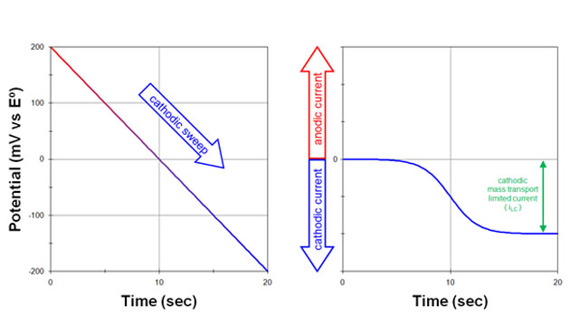
Fig 1. Response to a potential sweep (cathodic) from a solution initially containing only the oxidized form (O) with no reduced form (R)
| (7) |
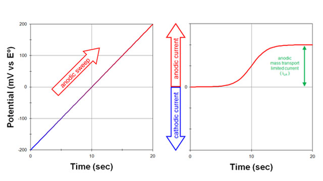
Fig 2. Response to a potential sweep (anodic) from a solution initially containing only the reduced form (R) with no oxidized form (O)
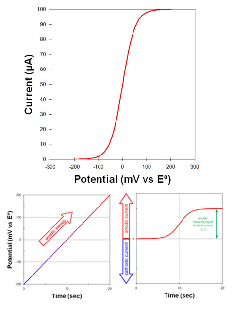
Fig 3. A voltammogram is a plot of current versus potential
3.1Voltammogram Plotting Conventions
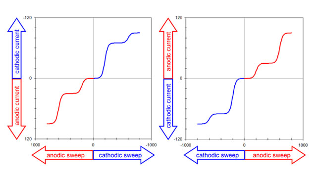
Fig 4. two popular voltammogram plotting conventions
3.2Measuring Limiting Currents
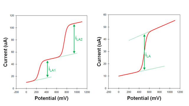
Fig 5. sloping background in voltammograms
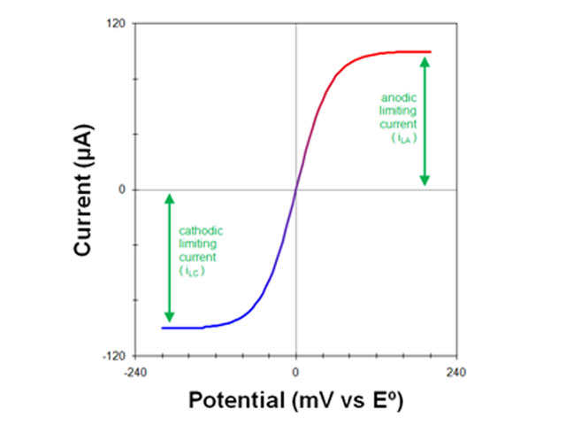
Fig 6. voltammogram of a solution containing both O and R
4Rotating Disk Electrode (RDE) Theory
| (8) |
| (9) |
Levich, V. G. Physicochemical hydrodynamics, 1st ed. Prentice-Hall: Englewood Cliffs, NJ, 1962.
| (10) |
| (11) |
4.1Levich Study
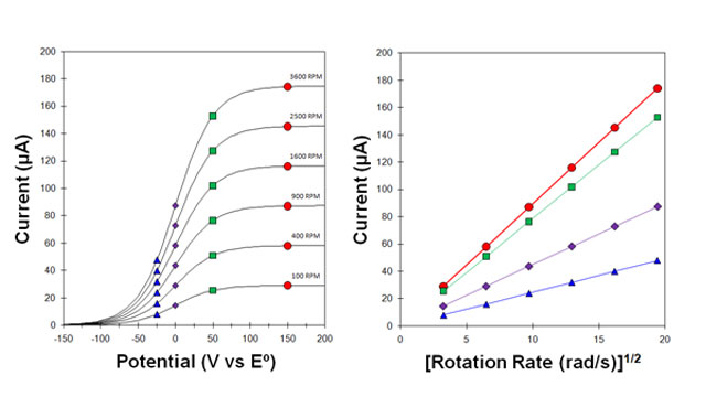
Fig 7. Levich Study - voltammograms at various rotation rates
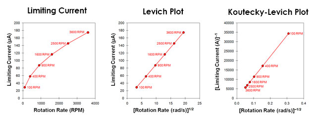
Fig 8. Levich Study - Limiting Current vs rotation rate and corresponding Levich and Koutecky-Levich plots.
| (12) |
Treimer, S.; Tang, A.; Johnson, D. C. A Consideration of the Application of Koutecký-Levich Plots in the Diagnoses of Charge-Transfer Mechanisms at Rotated Disk Electrodes. Electroanalysis, 2002, 14(3), 165-171. Again, for a simple and reversible half reaction with no complications, the data fall along a straight line that intercepts the vertical axis at zero. If the line intercepts the vertical axis above zero, however, this is a strong indication that the half-reaction is limited by sluggish kinetics rather than by mass transport.
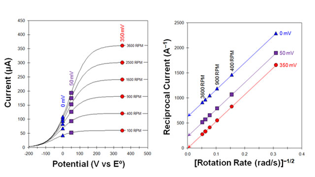
Fig 9. Koutecky-Levich Study - Voltammograms with sluggish kinetics
4.2Koutecky-Levich Analysis
| (13) |
5Rotating Ring-Disk Electrode (RRDE) Theory
Nekrasov, L. N.; Berezina, N. P. Use of a disc electrode with a ring in studying the electrolytic reduction of copper. Dokl. Akad. Nauk, 1962, 142(4), 855-858.
Müller, L.; Nekrasov, L. N. Study of the Cathodic Reduction of Oxygen on Platinum in Alkaline Solutions Using a Rotating Disk and Ring Electrode. Dokl. Akad. Nauk, 1963, 149(5), 1107-1110.
Müller, L.; Nekrasov, L. N. Study of the Electroreduction of Oxygen on Smooth Platinum in Acid Solutions by the Method of a Revolving Disc Electrode with a Ring. Dokl. Akad. Nauk SSSR, 1964, 154, 437. At the same time, Benjamin Levich and Yuri Ivanov began working on a theoretical description of solution flow at the RRDE. The four Russian researchers published their initial findings in 1959, and their work caught the attention of both Stanley Bruckenstein at the University of Minnesota and John Albery at Oxford University. Bruckenstein travelled to Moscow to learn more about the RRDE,
Albery, W. J. Ring-disc electrodes. Part 1.—A new approach to the theory. Trans. Faraday Soc., 1966, 62, 1915-1919.
Albery, W. J.; Bruckenstein, S. Ring-disc electrodes. Part 2.—Theoretical and experimental collection effciencies. Trans. Faraday Soc., 1966, 62, 1920-1931.
Albery, W. J.; Bruckenstein, S.; Napp, D. T. Ring-disc electrodes. Part 3.—Current-voltage curves at the ring electrode with simultaneous currents at the disc electrode. Trans. Faraday Soc., 1966, 62, 1932-1937.
Albery, W. J.; Bruckenstein, S.; Johnson, D. C. Ring-disc electrodes. Part 4.—Diffusion layer titration curves. Trans. Faraday Soc., 1966, 62, 1938-1945.
Albery, W. J.; Bruckenstein, S. Ring-disc electrodes. Part 5.—First-order kinetic collection effciencies at the ring electrode. Trans. Faraday Soc., 1966, 62, 1946-1954. and placed the new technique on a firm theoretical foundation. Albery returned to Oxford and (working with his student Michael Hitchman) drew these theoretical papers together in a seminal volume titled Ring-Disc Electrodes.
5.1Theoretical Computation of the Collection Efficiency
Albery, W. J.; Bruckenstein, S. Ring-disc electrodes. Part 2.—Theoretical and experimental collection effciencies. Trans. Faraday Soc., 1966, 62, 1920-1931. from the three principle diameters describing the RRDE geometry: the disk outer diameter (d1), the ring inner diameter (d2), and the ring outer diameter (d3). This somewhat tedious computation is made easier by normalizing the ring diameters with respect to the disk diameter as follows:
| (14) |
5.2Empirical Measurement of the Collection Efficiency
| (reduction of ferricyanide to ferrocyanide at disk) |
| (oxidation of ferrocyanide to ferricyanide at ring) |
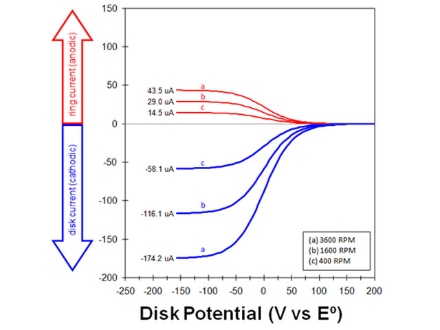
Fig 10. rotating ring-disk electrode voltammograms at various rotation rates
| (15) |
5.3Generator/Collector Experiments
| (reduction of A to unstable intermediate X at disk electrode) | |
| (chemical decay of X to electrochemically inactive Z) | |
| (oxidation of X back to A at ring electrode) |
| (16) |
| (17) |
5.4Comparing Two Competing Pathways
| (reduction of A to unstable intermediate X at disk electrode) | |
| (chemical decay of X to electrochemically inactive Z) | |
| (chemical decay of X to electrochemically active Y) | |
| (detection of Y at ring electrode via oxidation of Y to B) |
| (18) |
Gasteiger, H. A.; Kocha, S. S.; Sompalli, B.; Wagner, F. T. Activity benchmarks and requirements for Pt, Pt-alloy, and non-Pt oxygen reduction catalysts for PEMFCs. Appl. Catal., B, 2005, 56(1-2 SPEC. ISS.), 9–35.
Paulus, U. A.; Wokaun, A.; Scherer, G. G.; Schmidt, T. J.; Stamenkovic, V.; Markovic, N. M.; Ross, P. N. Oxygen reduction on high surface area Pt-based alloy catalysts in comparison to well defined smooth bulk alloy electrodes. Electrochim. Acta, 2002, 47(22-23), 3787–3798.
Paulus, U. A.; Schmidt, T. J.; Gasteiger, H. A.; Behm, R. J. Oxygen reduction on a high-surface area Pt/Vulcan carbon catalyst: A thin-film rotating ring-disk electrode study. J. Electroanal. Chem., 2001, 495(2), 134–145.
Schmidt, T. J.; Paulus, U. A.; Gasteiger, H. A.; Behm, R. J. The oxygen reduction reaction on a Pt/carbon fuel cell catalyst in the presence of chloride anions. J. Electroanal. Chem., 2001, 508(1-2), 41–47.
Brisard, G.; Bertrand, N.; Ross, P. N.; Marković, N. M. Oxygen reduction and hydrogen evolution–oxidation reactions on Cu(hkl) surfaces. J. Electroanal. Chem., 2000, 480(1-2), 219–224.
Geniès, L.; Faure, R.; Durand, R. Electrochemical reduction of oxygen on platinum nanoparticles in alkaline media. Electrochim. Acta, 1998, 44(8-9), 1317–1327.
Higuchi, E.; Uchida, H.; Watanabe, M. Effect of loading level in platinum-dispersed carbon black electrocatalysts on oxygen reduction activity evaluated by rotating disk electrode. J. Electroanal. Chem., 2005, 583(1), 69–76.
Wei, Z. D.; Chan, S. H.; Li, L. L.; Cai, H. F.; Xia, Z. T.; Sun, C. X. Electrodepositing Pt on a Nafion-bonded carbon electrode as a catalyzed electrode for oxygen reduction reaction. Electrochim. Acta, 2005, 50(11), 2279–2287.
Marcotte, S.; Villers, D.; Guillet, N.; Roué, L.; Dodelet, J. P. Electroreduction of oxygen on Co-based catalysts: Determination of the parameters affecting the two-electron transfer reaction in an acid medium. Electrochim. Acta, 2004, 50(1), 179–188.
Durón, S.; Rivera-Noriega, R.; Nkeng, P.; Poillerat, G.; Solorza-Feria, O. Kinetic study of oxygen reduction on nanoparticles of ruthenium synthesized by pyrolysis of Ru3(CO)12. J. Electroanal. Chem., 2004, 566(2), 281–289. When oxygen (O2) is dissolved in acidic media and reduced at a platinum electrode, one pathway leads to water as the ultimate reduction product while the other pathway leads to the formation of peroxide anions. In the context of hydrogen fuel cell research, the pathway which leads to water is preferred, and it is commonly called the four-electron pathway. The path to peroxide formation is called the two-electron pathway, and it is undesirable for a number of reasons, including the fact that peroxide can damage various polymer membrane materials found in a fuel cell. Further details on how to use an RRDE “generator/collector” experiment to distinguish between the two-electron and four-electron ORR pathways can be found in the electrochemical literature.
Paulus, U. A.; Schmidt, T. J.; Gasteiger, H. A.; Behm, R. J. Oxygen reduction on a high-surface area Pt/Vulcan carbon catalyst: A thin-film rotating ring-disk electrode study. J. Electroanal. Chem., 2001, 495(2), 134–145.
6Rotating Cylinder Electrode (RCE) Theory
Gabe, D. R.; Walsh, F. C. Enhanced mass transfer at the rotating cylinder electrode. II. Development of roughness for solutions of decreasing concentration. J. Appl. Electrochem., 1984, 14(5), 565–572.
Gabe, D. R.; Walsh, F. C. Enhanced mass transfer at the rotating cylinder electrode: III. Pilot and production plant experience. J. Appl. Electrochem., 1985, 15(6), 807–824. in the corrosion and electroplating communities. While the flow of solution at a rotating disk (or ring-disk) is laminar over a wide range of rotation rates, the flow at the surface of a rotating cylinder is turbulent
Silverman, D. C. Rotating Cylinder Electrode-Geometry Relationships for Prediction of Velocity-Sensitive Corrosion. Corrosion, 1988, 44(1), 42–49.
Silverman, D. C. Corrosion prediction in complex environments using electrochemical impedance spectroscopy. Electrochim. Acta, 1993, 38(14), 2075–2078.
Silverman, D. C. Technical Note: On Estimating Conditions for Simulating Velocity-Sensitive Corrosion in the Rotating Cylinder Electrode. Corrosion, 1999, 55(12), 1115–1118.
Silverman, D. C. Technical Note: Simplified Equation for Simulating Velocity-Sensitive Corrosion in the Rotating Cylinder Electrode at Higher Reynolds Numbers. Corrosion, 2003, 59(3), 207–211.
Silverman, D. C. The Rotating Cylinder Electrode for Examining Velocity-Sensitive Corrosion—A Review. Corrosion, 2004, 60(11), 1003–1023.
Silverman, D. C. Technical Note: Conditions for Similarity of Mass-Transfer Coefficients and Fluid Shear Stresses between the Rotating Cylinder Electrode and Pipe. Corrosion, 2005, 61(6), 515–518.
Wranglen, G.; Berendson, J.; Karlberg, G. Apparatus for Electrochemical Studies of Corrosion Processes in Flowing Systems. In Physicochemical Hydrodynamics, 1st ed.; Spalding, B.; Prentice-Hall: Englewood Cliffs, NJ, 1977.
Holser, R. A.; Prentice, G.; Pond, R. B.; Guanti, R. Use of Rotating Cylinder Electrodes to Simulate Turbulent Flow Conditions in Corroding Systems. Corrosion, 1990, 46(9), 764–769.
Chen, T. Y.; Moccari, A. A.; Macdonald, D. D. Development of Controlled Hydrodynamic Techniques for Corrosion Testing. Corrosion, 1992, 48(3), 239–255.
Nesic, S.; Solvi, G. T.; Skejerve, S. Comparison of rotating cylinder and loop methods for testing CO2 corrosion inhibitors. Br. Corros. J., 1997, 32(4), 269–276.
ASTM G170-01a Standard Guide for Evaluating and Qualifying Oilfield and Refinery Corrosion Inhibitors in the Laboratory. In ASTM International ATSM International: West Conshohocken, PA, 2012.
ASTM Editors ASTM G185-06 Standard Practice for Evaluating and Qualifying Oil Field and Refinery Corrosion Inhibitors Using the Rotating Cylinder Electrode ATSM International: West Conshohocken, PA, 2012.
Eisenberg, M.; Tobias, C. W.; Wilke, C. R. No title. Chemilca Engineering Progress Symposium Series, 1955, 51, 1. in 1954 (about the same time that Levich was describing the rotating disk electrode). Eisenberg’s work eventually led to the Eisenberg equation which gives the limiting current at a rotating cylinder electrode
| (19) |
Gabe, D. R.; Walsh, F. C. The rotating cylinder electrode: a review of development. J. Appl. Electrochem., 1983, 13(1), 3–21.
Gabe, D. R.; Walsh, F. C. Enhanced mass transfer at the rotating cylinder electrode: III. Pilot and production plant experience. J. Appl. Electrochem., 1985, 15(6), 807–824.
Kear, G.; Barker, B. D.; Stokes, K.; Walsh, F. C. Flow influenced electrochemical corrosion of nickel aluminium bronze – Part I. Cathodic polarisation. J. Appl. Electrochem., 2004, 34(12), 1235–1240.
Silverman, D. C. The Rotating Cylinder Electrode for Examining Velocity-Sensitive Corrosion—A Review. Corrosion, 2004, 60(11), 1003–1023.
7References
- Kissinger, P.; Heineman, W. R. Laboratory Techniques in Electroanalytical Chemistry, 2nd ed. Marcel Dekker, Inc: New York, 1996.
- Zoski, C. G.; Leddy, J.; Bard, A. J.; Electrochemical Methods: Fundamentals and Applications (Student Solutions Manual), 2nd ed. John Wiley: New York, 2002.
- Johnson, D. C.; Weber, S. G.; Bond, A. M.; Wightman, R. M.; Shoup, R. E.; Krull, I. S. Electroanalytical voltammetry in flowing solutions. Anal. Chim. Acta, 1986, 180, 187-250.
- Gunasingham, H.; Fleet, B. Wall-Jet Electrode in Continuous Monitoring Voltammetry. Anal. Chem., 1983, 55(8), 1409–1414.
- Macpherson, J. V.; Unwin, P. R. Hydrodynamic modulation voltammetry with an oscillating microjet electrode. Anal. Chem., 1999, 71(20), 4642–4648.
- Henley, I. E.; Yunus, K.; Fisher, A. C. Voltammetry under microfluidic control: Computer-aided design development and application of novel microelectrochemical reactors. J. Phys. Chem. B, 2003, 107(16), 3878–3884.
- Pratt, K. W.; Johnson, D. C. Vibrating wire electrodes-I. Literature review, design and evaluation. Electrochim. Acta, 1982, 27(8), 1013–1021.
- Hagan, C.; Coury, L. a. Comparison of hydrodynamic voltammetry implemented by sonication to a rotating disk electrode. Anal. Chem., 1994, 66(3), 399–405.
- Levich, V. G. Physicochemical hydrodynamics, 1st ed. Prentice-Hall: Englewood Cliffs, NJ, 1962.
- Bruckenstein, S.; Nagai, T. The Rotated, Mercury-Coated Platinum Electrode. Anal. Chem., 1961, 33(9), 1201-1209.
- Galus, Z.; Olson, C.; Lee, H. Y.; Adams, R. N. Rotating Disk Electrodes. Anal. Chem., 1962, 34(1), 164.
- Albery, W. J.; Bell, R. P. The Kinetics of the Dissociation of Weak Acids Measured by a Rotating Platinum Disc Electrode. Proc. Chem. Soc., 1963, 169.
- Bruckenstein, S.; Miller, B. Unraveling reactions with rotating electrodes. Acc. Chem. Res., 1976, 84(2), 54–61.
- Treimer, S.; Tang, A.; Johnson, D. C. A Consideration of the Application of Koutecký-Levich Plots in the Diagnoses of Charge-Transfer Mechanisms at Rotated Disk Electrodes. Electroanalysis, 2002, 14(3), 165-171.
- Dalton, F. ECS Classics: Historical Origins of the Rotating Ring-Disk Electrode. Electrochem. Soc. Interface, 2016, 25(3), 50–59.
- Frumkin, A. N.; Nekrasov, L. N.; Levich, B.; Ivanov, J. The Use of a Rotating Ring-Disk Electrode for Studying Intermediate Products of Electrochemical Reactions. J. Electroanal. Chem., 1959, 1, 84–90.
- Nekrasov, L. N.; Berezina, N. P. Use of a disc electrode with a ring in studying the electrolytic reduction of copper. Dokl. Akad. Nauk, 1962, 142(4), 855-858.
- Müller, L.; Nekrasov, L. N. Study of the Electroreduction of Oxygen on Smooth Platinum in Acid Solutions by the Method of a Revolving Disc Electrode with a Ring. Dokl. Akad. Nauk SSSR, 1964, 154, 437.
- Müller, L.; Nekrasov, L. N. Study of the Cathodic Reduction of Oxygen on Platinum in Alkaline Solutions Using a Rotating Disk and Ring Electrode. Dokl. Akad. Nauk, 1963, 149(5), 1107-1110.
- Bruckenstein, S. The Relations Between the Limiting Diffusion Currents at Rotating Disk, Ring, and Ring-Disk Electrodes. Elektrokhimiya , 1966, 2, 1085.
- Albery, W. J.; Hitchman, M. L. Ring-Disc Electrodes Oxford University Press: Oxford, England, 1971.
- Albery, W. J. Ring-disc electrodes. Part 1.—A new approach to the theory. Trans. Faraday Soc., 1966, 62, 1915-1919.
- Albery, W. J.; Bruckenstein, S. Ring-disc electrodes. Part 2.—Theoretical and experimental collection effciencies. Trans. Faraday Soc., 1966, 62, 1920-1931.
- Albery, W. J.; Bruckenstein, S.; Napp, D. T. Ring-disc electrodes. Part 3.—Current-voltage curves at the ring electrode with simultaneous currents at the disc electrode. Trans. Faraday Soc., 1966, 62, 1932-1937.
- Albery, W. J.; Bruckenstein, S.; Johnson, D. C. Ring-disc electrodes. Part 4.—Diffusion layer titration curves. Trans. Faraday Soc., 1966, 62, 1938-1945.
- Albery, W. J.; Bruckenstein, S. Ring-disc electrodes. Part 5.—First-order kinetic collection effciencies at the ring electrode. Trans. Faraday Soc., 1966, 62, 1946-1954.
- Eisenberg, M.; Tobias, C. W.; Wilke, C. R. Ionic Mass Transfer and Concentration Polarization at Rotating Electrodes. Journal of The Electrochemical Society, 1954, 101(6), 306.
- Eisenberg, M.; Tobias, C. W.; Wilke, C. R. No title. Chemilca Engineering Progress Symposium Series, 1955, 51, 1.
- Gabe, D. R. The rotating cylinder electrode. J. Appl. Electrochem., 1974, 4(2), 91–108.
- Gabe, D. R.; Robinson, D. J. Mass transfer in a rotating cylinder cell—I. Laminar flow. Electrochim. Acta, 1972, 17(6), 1121–1127.
- Gabe, D. R.; Robinson, D. J. Mass transfer in a rotating cylinder cell—II. Turbulent Flow. Electrochim. Acta, 1972, 17(6), 1129–1137.
- Gabe, D. R.; Walsh, F. C. The rotating cylinder electrode: a review of development. J. Appl. Electrochem., 1983, 13(1), 3–21.
- Garsany, Y.; Baturina, O. A.; Swider-Lyons, K. E.; Kocha, S. S. Experimental methods for quantifying the activity of platinum electrocatalysts for the oxygen reduction reaction. Anal. Chem., 2010, 82(15), 6321–6328.
- Gasteiger, H. A.; Kocha, S. S.; Sompalli, B.; Wagner, F. T. Activity benchmarks and requirements for Pt, Pt-alloy, and non-Pt oxygen reduction catalysts for PEMFCs. Appl. Catal., B, 2005, 56(1-2 SPEC. ISS.), 9–35.
- Paulus, U. A.; Wokaun, A.; Scherer, G. G.; Schmidt, T. J.; Stamenkovic, V.; Markovic, N. M.; Ross, P. N. Oxygen reduction on high surface area Pt-based alloy catalysts in comparison to well defined smooth bulk alloy electrodes. Electrochim. Acta, 2002, 47(22-23), 3787–3798.
- Paulus, U. A.; Schmidt, T. J.; Gasteiger, H. A.; Behm, R. J. Oxygen reduction on a high-surface area Pt/Vulcan carbon catalyst: A thin-film rotating ring-disk electrode study. J. Electroanal. Chem., 2001, 495(2), 134–145.
- Schmidt, T. J.; Paulus, U. A.; Gasteiger, H. A.; Behm, R. J. The oxygen reduction reaction on a Pt/carbon fuel cell catalyst in the presence of chloride anions. J. Electroanal. Chem., 2001, 508(1-2), 41–47.
- Brisard, G.; Bertrand, N.; Ross, P. N.; Marković, N. M. Oxygen reduction and hydrogen evolution–oxidation reactions on Cu(hkl) surfaces. J. Electroanal. Chem., 2000, 480(1-2), 219–224.
- Geniès, L.; Faure, R.; Durand, R. Electrochemical reduction of oxygen on platinum nanoparticles in alkaline media. Electrochim. Acta, 1998, 44(8-9), 1317–1327.
- Higuchi, E.; Uchida, H.; Watanabe, M. Effect of loading level in platinum-dispersed carbon black electrocatalysts on oxygen reduction activity evaluated by rotating disk electrode. J. Electroanal. Chem., 2005, 583(1), 69–76.
- Wei, Z. D.; Chan, S. H.; Li, L. L.; Cai, H. F.; Xia, Z. T.; Sun, C. X. Electrodepositing Pt on a Nafion-bonded carbon electrode as a catalyzed electrode for oxygen reduction reaction. Electrochim. Acta, 2005, 50(11), 2279–2287.
- Marcotte, S.; Villers, D.; Guillet, N.; Roué, L.; Dodelet, J. P. Electroreduction of oxygen on Co-based catalysts: Determination of the parameters affecting the two-electron transfer reaction in an acid medium. Electrochim. Acta, 2004, 50(1), 179–188.
- Durón, S.; Rivera-Noriega, R.; Nkeng, P.; Poillerat, G.; Solorza-Feria, O. Kinetic study of oxygen reduction on nanoparticles of ruthenium synthesized by pyrolysis of Ru3(CO)12. J. Electroanal. Chem., 2004, 566(2), 281–289.
- Silverman, D. C.; Zerr, M. E. Application of the Rotating Cylinder Electrode—E-Brite 26-1/Concentrated Sulfuric Acid. Corrosion, 1986, 42(11), 633–640.
- Gabe, D. R.; Walsh, F. C. Enhanced mass transfer at the rotating cylinder electrode. I. Characterization of a smooth cylinder and roughness development in solutions of constant concentration. J. Appl. Electrochem., 1984, 14(5), 555–564.
- Gabe, D. R.; Walsh, F. C. Enhanced mass transfer at the rotating cylinder electrode. II. Development of roughness for solutions of decreasing concentration. J. Appl. Electrochem., 1984, 14(5), 565–572.
- Gabe, D. R.; Walsh, F. C. Enhanced mass transfer at the rotating cylinder electrode: III. Pilot and production plant experience. J. Appl. Electrochem., 1985, 15(6), 807–824.
- Gabe, D. R.; Makanjuola, P. A. Enhanced mass transfer using roughened rotating cylinder electrodes in turbulent flow. J. Appl. Electrochem., 1987, 17(2), 370–384.
- Gabe, D. R.; Wilcox, G. D.; Gonzalez-Garcia, J.; Walsh, F. C. The rotating cylinder electrode: its continued development and application. J. Appl. Electrochem., 1998, 28(8), 759–780.
- Kear, G.; Barker, B. D.; Stokes, K.; Walsh, F. C. Flow influenced electrochemical corrosion of nickel aluminium bronze – Part I. Cathodic polarisation. J. Appl. Electrochem., 2004, 34(12), 1235–1240.
- Kear, G.; Barker, B. D.; Stokes, K.; Walsh, F. C. Flow influenced electrochemical corrosion of nickel aluminium bronze – Part II. Anodic polarisation and derivation of the mixed potential. J. Appl. Electrochem., 2004, 34(12), 1241–1248.
- Lu, Q.; Stack, M. M.; Wiseman, C. R. AC impedance spectroscopy as a technique for investigating corrosion of iron in hot flowing Bayer liquors. J. Appl. Electrochem., 2001, 31(12), 1373–1379.
- Maciel, J. M.; Agostinho, S. M. L. Use of a rotating cylinder electrode in corrosion studies of a 90/10 Cu-Ni alloy in 0.5 M L-1 H2SO4 media. J. Appl. Electrochem., 2000, 30(8), 981–985.
- Grau, J. M.; Bisang, J. M. Mass transfer studies at rotating cylinder electrodes of expanded metal. J. Appl. Electrochem., 2005, 35(3), 285–291.
- Eklund, A.; Simonsson, D. Enhanced mass transfer to a rotating cylinder electrode with axial flow. J. Appl. Electrochem., 1988, 18(5), 710–714.
- Efird, K. D.; Wright, E. J.; Boros, J. A.; Hailey, T. G. Correlation of steel corrosion in pipe flow with jet impingement and rotating cylinder tests. Corrosion, 1993, 49(12), 992–1003.
- Silverman, D. C. Rotating Cylinder Electrode for Velocity Sensitivity Testing. Corrosion, 1984, 40(5), 220–226.
- Silverman, D. C. Rotating Cylinder Electrode-Geometry Relationships for Prediction of Velocity-Sensitive Corrosion. Corrosion, 1988, 44(1), 42–49.
- Silverman, D. C. Corrosion prediction in complex environments using electrochemical impedance spectroscopy. Electrochim. Acta, 1993, 38(14), 2075–2078.
- Silverman, D. C. Technical Note: On Estimating Conditions for Simulating Velocity-Sensitive Corrosion in the Rotating Cylinder Electrode. Corrosion, 1999, 55(12), 1115–1118.
- Silverman, D. C. Technical Note: Simplified Equation for Simulating Velocity-Sensitive Corrosion in the Rotating Cylinder Electrode at Higher Reynolds Numbers. Corrosion, 2003, 59(3), 207–211.
- Silverman, D. C. The Rotating Cylinder Electrode for Examining Velocity-Sensitive Corrosion—A Review. Corrosion, 2004, 60(11), 1003–1023.
- Silverman, D. C. Technical Note: Conditions for Similarity of Mass-Transfer Coefficients and Fluid Shear Stresses between the Rotating Cylinder Electrode and Pipe. Corrosion, 2005, 61(6), 515–518.
- Wranglen, G.; Berendson, J.; Karlberg, G. Apparatus for Electrochemical Studies of Corrosion Processes in Flowing Systems. In Physicochemical Hydrodynamics, 1st ed.; Spalding, B.; Prentice-Hall: Englewood Cliffs, NJ, 1977.
- Holser, R. A.; Prentice, G.; Pond, R. B.; Guanti, R. Use of Rotating Cylinder Electrodes to Simulate Turbulent Flow Conditions in Corroding Systems. Corrosion, 1990, 46(9), 764–769.
- Chen, T. Y.; Moccari, A. A.; Macdonald, D. D. Development of Controlled Hydrodynamic Techniques for Corrosion Testing. Corrosion, 1992, 48(3), 239–255.
- Nesic, S.; Solvi, G. T.; Skejerve, S. Comparison of rotating cylinder and loop methods for testing CO2 corrosion inhibitors. Br. Corros. J., 1997, 32(4), 269–276.
- ASTM G170-01a Standard Guide for Evaluating and Qualifying Oilfield and Refinery Corrosion Inhibitors in the Laboratory. In ASTM International ATSM International: West Conshohocken, PA, 2012.
- ASTM Editors ASTM G185-06 Standard Practice for Evaluating and Qualifying Oil Field and Refinery Corrosion Inhibitors Using the Rotating Cylinder Electrode ATSM International: West Conshohocken, PA, 2012.


