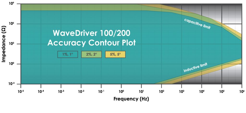
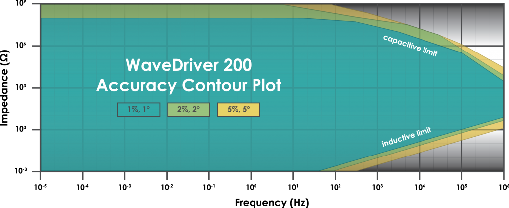
Sense line with driven shield
1
Drive line with grounded shield
Separate sense and drive lines, each with driven shield
(current measurement via passive shunt)
N/A
The DC Common is isolated from the USB port, the instrument chassis and earth ground. The DC Common is accessible via abanana binding post (black) on the back panel.
The instrument chassis terminal is accessible via a banana binding post (metal) on the back panel. The GRAY banana plug on the cell cable also provides a chassis connection to allow convenient connection of the instrument chassis to a Faraday cage surrounding the electrochemical cell.
No direct connection to earth ground is provided.
±1 A, ±100 mA, ±10 mA, ±1 mA, ±100 μA, ±10 μA, ±1 μA, ±100 nA
31.3 μA, 3.13 μA, 313 nA, 31.3 nA, 3.13 nA, 313 pA, 31.3 pA, 3.13 pA
Yes
20 pA to 1.0 A
±0.2% of setting; ±0.05% of range
<10 pA at 25˚C
Frequency- and range-dependent to 1 MHz
Frequency- and range-dependent to 1 MHz
16 bits
10 Hz, 30 Hz, 100 Hz, 1 kHz, 10 kHz (2-pole, low pass Bessel filters)
±1 A, ±100 mA, ±10 mA, ±1 mA, ±100 μA, ±10 μA, ±1 μA, ±100 nA
31.3 μA, 3.13 μA, 313 nA, 31.3 nA, 3.13 nA, 313 pA, 31.3 pA, 3.13 pA
±0.2% of setting; ±0.05% of range
16 bits
±1.0 A (maximum)
1 A, 100 mA ranges: < 1.3 A
10 mA −100 nA ranges: < 200 mA
>±17 V
>2.5 MHz (on fastest speed setting)
< 35 µVRMS in 2 MHz bandwidth
10 V/μs (on fastest speed setting)
>1013 Ω in parallel with <10 pF
<10 pA leakage/bias current at 25˚C
>100 dB 0 − 1 kHz; >74 dB at 10 kHz
>15 MHz (3 dB)
±15.0 V, ±10.0 V, ±2.5 V
469 μV, 313 μV, 78 μV per DAC bit
±0.2% of setting, ±0.05% of range
16 bits
10 Hz, 30 Hz, 100 Hz, 1 kHz, 10 kHz (2-pole, low pass Bessel filters)
±15.0 V, ±10.0 V, ±2.5 V
469 μV, 313 μV, 78 μV per DAC bit
±0.2% of setting, ±0.05% of range
16 bits
10 μV/s (469 μV per 46.9 s, 313 μV step per 31.3 s or 78 μV per 7.8 s)
75 V/s
10 ns (minimum time base)
80 μs (minimum)
Simultaneous sampling of all analog input signals
<10 million per experiment
Yes
10 μHz – 1 MHz
<1 ppm 1MHz – 100 mHz, <8 ppm 100 mHz – 10 mHz, <90 ppm 10 mHz – 1 mHz, <700 ppm 1mHz – 10 μHz
±10 ppm
Potentiostatic/Galvanostatic
1 mV – 200 mV peak, ±10% of setting
0.01% − 100% of current range, ±10% of setting, 200 mA max
Linear/Logarithmic/Custom List
7-pin mini circular DIN includes analog and digital signal grounds, digital rotator enable signal (+15 V max), auxiliary digital output signal, and analog rotation rate control signal
3-pin connector includes analog signal ground, digital rotator enable signal (+15 V max), and analog rotation rate control signal
±10.0 V, ±2.5 V
Open drain with 4.7 kΩ pull up to +5 V (TTL compatible)
External dummy cell (included)
Combination D-SUB connector to multiple banana plugs via shielded coaxial cables (included)
9-pin DSUB connector that includes DC Common, two digital output signals, and two digital input signals
BNC female, TTL compatible
BNC female, TTL compatible
N/A
N/A
N/A
N/A
N/A
BNC female, ±10 V differential input, 313 μV resolution, 0.2% accuracy (available when second working electrode not in use)
BNC female, ±10 V bipolar output, 313 μV resolution, 0.2% accuracy (available when second working electrode not in use)
24.0 VDC (±5%), 5.0 A (low voltage DC device)
Input Requirements: 100 to 240 VAC, 1.4 to 0.7 A, 50 to 60 Hz Output Power: 24 VAC, 5.0 A Power supply (included) has a C14 type input connector
Various international cables sold separately (C13 type)
Power, USB, and status
160 × 324 × 255 mm
(6.3 × 12.75 × 10.0 in)
4.6 kg (10.2 lb)
254 × 356 × 457 mm
(10 × 14 × 18 in)
7.7 kg (17 lb)
10 °C – 40 °C
80% RH maximum, non-condensing
USB
No
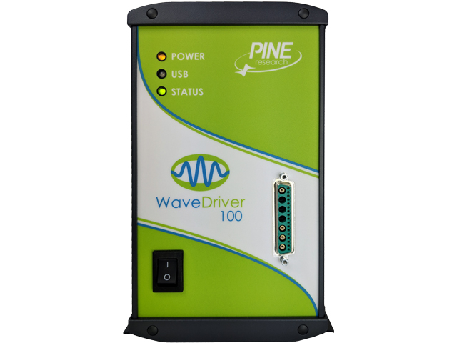 Product Page
Quick Specification Overview
| Working Electrode Channels | 1 |
| Measured Current Ranges | ±1 A, ±100 mA, ±10 mA, ±1 mA, ±100 μA, ±10 μA, ±1 μA, ±100 nA |
| Autoranging | Yes |
| Practical Current Range | 20 pA to 1.0 A |
| ADC Input | 16 bits |
| Compliance Voltage | >±17 V |
| Measured Potential Ranges | ±15.0 V, ±10.0 V, ±2.5 V |
| CV Sweep Rate (min) | 10 μV/s (469 μV per 46.9 s, 313 μV step per 31.3 s or 78 μV per 7.8 s) |
| CV Sweep Rate (max) | 75 V/s |
| Point Interval | 80 μs (minimum) |
| EIS Capable | Yes |
| EIS Frequency Range | 10 μHz - 1 MHz |
| Instrument Dimensions | 160 × 324 × 255 mm (6.3 × 12.75 × 10.0 in) |
| Instrument Weight | 4.6 kg (10.2 lb) |
| Interface | USB |
| Wireless Capable | No |
Sense line with driven shield
Drive line with grounded shield
2
Separate sense and drive lines, each with driven shield
(current measurement via passive shunt)
Separate sense and drive lines, each with driven shield (current measurement via transimpedance amplifier). Note: AC techniques are not available on K2.
The DC Common is isolated from the USB port, the instrument chassis and earth ground. The DC Common is accessible via a banana binding post (black) on the back panel.
The instrument chassis terminal is accessible via a banana binding post (metal) on the back panel. The GRAY banana plug on the cell cable also provides a chassis connection to allow convenient connection of the instrument chassis to a Faraday cage surrounding the electrochemical cell.
No direct connection to earth ground is provided.
±1 A, ±100 mA, ±10 mA, ±1 mA, ±100 μA, ±10 μA, ±1 μA, ±100 nA
31.3 μA, 3.13 μA, 313 nA, 31.3 nA, 3.13 nA, 313 pA, 31.3 pA, 3.13 pA
Yes
20 pA to 1.0 A
±0.2% of setting; ±0.05% of range
< 10 pA at 25˚C
Frequency- and range-dependent to 1 MHz
Frequency- and range-dependent to 1 MHz
16 bits
10 Hz, 30 Hz, 100 Hz, 1 kHz, 100 kHz (2-pole, low pass Bessel filters)
±1 A, ±100 mA, ±10 mA, ±1 mA, ±100 μA, ±10 μA, ±1 μA, ±100 nA
31.3 μA, 3.13 μA, 313 nA, 31.3 nA, 3.13 nA, 313 pA, 31.3 pA, 3.13 pA
±0.2% of setting; ±0.05% of range
16 bits
±1.0 A (maximum)
1 A, 100 mA ranges: < 1.3 A
10 mA − 100 nA ranges: < 200 mA
±17 V
> 2.5 MHz (on fastest speed setting)
< 35 µVRMS in 2 MHz bandwidth
10 V/μs (on fastest speed setting)
> 1012 Ω in parallel with < 10 pF
< 10 pA leakage/bias current at 25˚C
>100 dB 0 – 1 kHz, >80 dB ≤ 10 kHz, >60 dB ≤ 100 kHz, >40 dB ≤ 1 MHz
>15 MHz (3 dB)
±15.0 V, ±10.0 V, ±2.5 V
469 μV, 313 μV, 78 μV per DAC bit
±0.2% of setting, ±0.05% of range
16 bits
10 Hz, 30 Hz, 100 Hz, 1 kHz (2-pole, low pass Bessel filters)
±15.0 V, ±10.0 V, ±2.5 V
469 μV, 313 μV, 78 μV per DAC bit
±0.2% of setting, ±0.05% of range
16 bits
10 μV/s (469 μV step per 46.9 s, 313 μV step per 31.3 s, or 78 μV per 7.8 s)
75 V/s
10 ns (minimum time base)
80 μs (minimum)
Simultaneous sampling of all analog input signals
< 10 million per experiment
Yes
10 μHz – 1 MHz
<1 ppm 1 MHz – 100 mHz, <80 ppm 100 mHz – 10 mHz, <90 ppm 10 mHz – 1 mHz, <700 ppm 1 mHz – 10 μHz
±10 ppm
Potentiostatic/Galvanostatic
1 mV – 200 mV peak, ±10% of setting
0.01% – 100% of current range, ±10% of setting, 200 mA max
Linear/Logarithmic/Custom List
7-pin mini circular DIN includes analog and digital signal grounds, digital rotator enable signal (+15 V max), auxiliary digital output signal, and analog rotation rate control signal
3-pin connector includes analog signal ground, digital rotator enable signal (+15 V max), and analog rotation rate control signal
±10.0 V, ±2.5 V
Open drain with 4.7 kΩ pull up to +5 V (TTL compatible)
External dummy cell (included)
Combination D-SUB connector to multiple banana plugs via shielded coaxial cables (included)
9-pin DSUB connector that includes DC Common, two digital output signals, and two digital input signals
BNC female, TTL compatible
BNC female, TTL compatible
BNC female, ±10V differential input, 20 kΩ impedance, ±0.5% accuracy; allows external waveform to be summed directly to the working electrode excitation signal
BNC female, ±15 V, ±10 V, ±2.5 V output, ±0.5% accuracy
BNC female, ±10 V output, scaled to current range, ±0.5% accuracy
BNC female, ±15 V, ±10 V, ±2.5 V output, ±0.5% accuracy
BNC female, ±10 V output, scaled to current range, ±0.5% accuracy
BNC female, ±10 V differential input, 313 μV resolution, 0.2% accuracy (available when second working electrode not in use)
BNC female, ±10 V bipolar output, 313 μV resolution, 0.2% accuracy (available when second working electrode not in use)
24.0 VDC (±5%), 5.0 A (low voltage DC device)
Input: 100 – 240 VAC, 1.4 – 0.7 A, 50 – 60 Hz
Output: 24 VDC, 5.0 A power supply (included) has a C14 type input connector
Various international cables sold separately (C13 type)
Power, USB, and status
160 × 324 × 255 mm
(6.3 × 12.75 × 10.0 in)
4.6 kg (10.2 lb)
254 × 356 × 457 mm
(10 × 14 × 18 in)
7.7 kg (17 lb)
10℃ to 40℃
80% RH maximum, non-condensing
USB
No
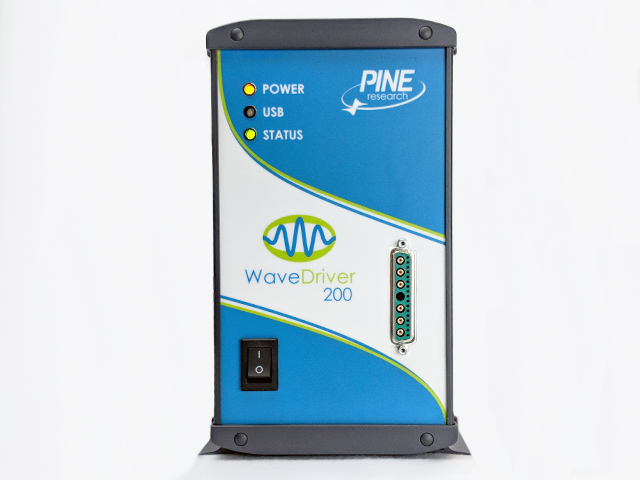 Product Page
Quick Specification Overview
| Working Electrode Channels | 2 |
| Measured Current Ranges | ±1 A, ±100 mA, ±10 mA, ±1 mA, ±100 μA, ±10 μA, ±1 μA, ±100 nA |
| Autoranging | Yes |
| Practical Current Range | 20 pA to 1.0 A |
| ADC Input | 16 bits |
| Compliance Voltage | ±17 V |
| Measured Potential Ranges | ±15.0 V, ±10.0 V, ±2.5 V |
| CV Sweep Rate (min) | 10 μV/s (469 μV step per 46.9 s, 313 μV step per 31.3 s, or 78 μV per 7.8 s) |
| CV Sweep Rate (max) | 75 V/s |
| Point Interval | 80 μs (minimum) |
| EIS Capable | Yes |
| EIS Frequency Range | 10 μHz - 1 MHz |
| Instrument Dimensions | 160 × 324 × 255 mm (6.3 × 12.75 × 10.0 in) |
| Instrument Weight | 4.6 kg (10.2 lb) |
| Interface | USB |
| Wireless Capable | No |
Sense line with driven shield
Drive line with grounded shield
1
Separate sense and drive lines, each with driven shield
(current measurement via passive shunt)
N/A
The signal ground (DC Common) is isolated from the USB port and floats with respect to the instrument chassis and earth ground. The signal ground is accessible via the black banana plug on the cell cable
The metal case (chassis) terminal is a banana binding post (back panel) which may optionally be used to connect the chassis to earth ground or signal ground to improve noise screening (shielding).
No direct connection to earth ground is provided. The chassis may (either intentionally or unknowingly) be connected to earth ground via a USB cable connected to a remote computer.
±1 A, ±100 mA, ±10 mA, ±1 mA, ±100 μA, ±10 μA, ±1 μA, ±100 nA
31.3 μA, 3.13 μA, 313 nA, 31.3 nA, 3.13 nA, 313 pA, 31.3 pA, 3.13 pA
Yes
100 pA to 1.0 A
±0.2% of setting; ±0.05% of range
<10 pA at 25˚C
N/A
N/A
16 bits
10 Hz, 30 Hz, 100 Hz, 1 kHz, 10 kHz (2-pole, low pass Bessel filters)
±1 A, ±100 mA, ±10 mA, ±1 mA, ±100 μA, ±10 μA, ±1 μA, ±100 nA
31.3 μA, 3.13 μA, 313 nA, 31.3 nA, 3.13 nA, 313 pA, 31.3 pA, 3.13 pA
±0.2% of setting; ±0.05% of range
16 bits
±1.0 A (maximum)
undertermined
± 16.5 V
>200 kHz (on fastest speed setting)
undertermined
10 V/μs (on fastest speed setting)
> 1013 Ω in parallel with < 10 pF
<10 pA leakage/bias current at 25˚C
>100 dB 0 − 1 kHz; >74 dB at 10 kHz
>11 MHz (3 dB)
±10.0 V, ±2.5 V
313 μV, 78 μV per DAC bit
±0.2% of setting, ±0.05% of range
16 bits
10 Hz, 30 Hz, 100 Hz, 1 kHz, 10 kHz (2-pole, low pass Bessel filters)
±10.0 V, ±2.5 V
313 μV, 78 μV per DAC bit
±0.2% of setting, ±0.05% of range
16 bits
10 μV/s (313 μV step per 31.3 s or 78 μV per 7.8 s)
125 V/s (10 mV step per 1.0 ms)
10 ns (minimum time base)
80 μs (minimum)
Simultaneous sampling of all analog input signals
<10 million per experiment
No
N/A
N/A
N/A
N/A
N/A
N/A
N/A
N/A
7-pin mini circular DIN includes analog and digital signal grounds, digital rotator enable signal, auxiliary digital output signal, and analog rotation rate control signal
3-pin connector includes analog signal ground, digital rotator enable signal, and analog rotation rate control signal
±10.0 V, ±2.5 V
open drain (TTL compatible)
External dummy cell (included)
Combination D-SUB connector to multiple banana plugs via shielded coaxial cables (included)
9-pin DSUB connector includes digital signal ground, two digital output signals, and three digital input signals
BNC female, TTL compatible
BNC female, TTL compatible
BNC female, ±10 V differential input, 20 kΩ impedance, ±0.5% accuracy; allows external waveform to be summed directly to the working electrode excitation signal. K2 Input available only on WaveDriver 20 bipotentiostat.
N/A
N/A
N/A
N/A
N/A
BNC female, ±10 V bipolar output, 313 μV resolution, 0.2% accuracy
24.0 VDC (±5%), 4.0 A (low voltage DC device)
Input Requirements: 100 to 240 VAC, 2.3 A, 50 to 60 Hz; C13 type connector Output Power: 24 VDC, 4.2 APower supply (included)
Various international cables sold separately (C13 type)
Power, USB, and status
160 × 324 × 255 mm
(6.3 × 12.75 × 10.0 in)
3.6 kg (8 lb)
254 × 356 × 457 mm
(10 × 14 × 18 in)
7.7 kg (17 lbs)
10 °C – 40 °C
80% RH maximum, non-condensing
USB
No
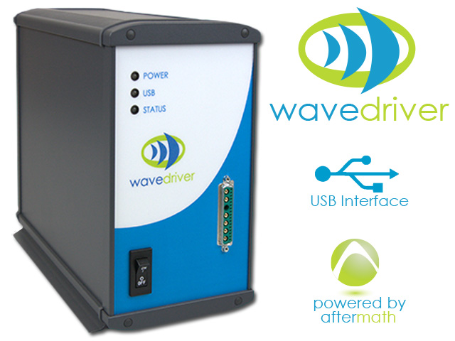 Product Page
Quick Specification Overview
| Working Electrode Channels | 1 |
| Measured Current Ranges | ±1 A, ±100 mA, ±10 mA, ±1 mA, ±100 μA, ±10 μA, ±1 μA, ±100 nA |
| Autoranging | Yes |
| Practical Current Range | 100 pA to 1.0 A |
| ADC Input | 16 bits |
| Compliance Voltage | ± 16.5 V |
| Measured Potential Ranges | ±10.0 V, ±2.5 V |
| CV Sweep Rate (min) | 10 μV/s (313 μV step per 31.3 s or 78 μV per 7.8 s) |
| CV Sweep Rate (max) | 125 V/s (10 mV step per 1.0 ms) |
| Point Interval | 80 μs (minimum) |
| EIS Capable | No |
| EIS Frequency Range | N/A |
| Instrument Dimensions | 160 × 324 × 255 mm (6.3 × 12.75 × 10.0 in) |
| Instrument Weight | 3.6 kg (8 lb) |
| Interface | USB |
| Wireless Capable | No |
Sense line with driven shield
Drive line
1
Separate sense and drive lines, each with driven shield (current measurement via passive shunt)
N/A
The DC Common is accessible via the black banana plug on the cell cable and the center pin on the Rotator Control Port
The metal case (chassis) is connected to the shield on the Cell Port and the shield on the USB Port. As shipped from the factory, the instrument chassis and DC Common are connected. A jumper on the circuit board may be removed to allow the DC Common to float with respect to the chassis.
No direct connection to earth ground is provided. The chassis may (either intentionally or unknowingly) be connected to earth ground via a USB cable connected to a remote computer.
±100 mA, ±5 mA, ±200 μA, ±10 μA
3.4 μA, 170 nA, 6.8 nA, and 340 pA
Yes
1 nA to 100 mA
±0.2% of setting, ±0.05% of range
10 pA at 25˚C
N/A
N/A
16 bits
2.5 kHz (2-pole, low pass filter)
±100 mA, ±5 mA, ±200 μA, ±10 μA
3.1 μA, 156 nA, 6.25 nA, and 313 pA
±0.2% of setting, ±0.05% of range
16 bits
±100.0 mA (maximum)
undertermined
± 12 V
> 20 kHz (on “fast” speed setting)
Undetermined
180 V/msec (on “fast” speed setting)
> 1014 Ω in parallel with < 20 pF
< 2 pA leakage/bias current at 25˚C
> 50 dB at 10 kHz; 80 dB at 60 Hz
> 800 kHz (3 dB)
±4.0 V
136 μV per DAC bit
±0.2% of setting, ±0.05% of range
16 bits
2.5 kHz (2-pole, low pass filter)
±4.0 V
125 μV per DAC bit
±0.2% of setting, ±1.0 mV
16 bits
10 μV / sec (125 μV step every 12.5 sec)
10 V/sec (10 mV step every 1.0 msec)
500 nsec (minimum time base)
500 μsec (minimum)
simultaneous current & potential input
<10 million per experiment
No
N/A
N/A
N/A
N/A
N/A
N/A
N/A
N/A
N/A
3-pin connector includes analog signal ground, digital rotator enable signal, and analog rotation rate control signal
±10.5 V
open drain (TTL compatible)
External dummy cell (included)
HD-15 male connector to multiple banana plugs via shielded coaxial cables (included), other designs available
N/A
N/A
N/A
N/A
N/A
N/A
N/A
N/A
N/A
N/A
5.0 VDC, 2 A (low voltage DC device)
100 to 240 VAC, 300 mA, 50 to 60 Hz
Various international cables sold separately (C13 type)
Power, USB, and status
165 × 100 × 29 mm
(6.5 × 3.9 × 1.1 in)
280 g (10 oz.)
260 × 260 × 360 mm
(10.2 × 10.2 × 14.2 in.)
1.4 kg (3 lb)
10℃ to 40℃
80% RH maximum, non-condensing
USB
No
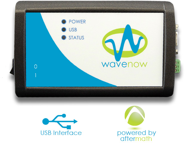 Product Page
Quick Specification Overview
| Working Electrode Channels | 1 |
| Measured Current Ranges | ±100 mA, ±5 mA, ±200 μA, ±10 μA |
| Autoranging | Yes |
| Practical Current Range | 1 nA to 100 mA |
| ADC Input | 16 bits |
| Compliance Voltage | ± 12 V |
| Measured Potential Ranges | ±4.0 V |
| CV Sweep Rate (min) | 10 μV / sec (125 μV step every 12.5 sec) |
| CV Sweep Rate (max) | 10 V/sec (10 mV step every 1.0 msec) |
| Point Interval | 500 μsec (minimum) |
| EIS Capable | No |
| EIS Frequency Range | N/A |
| Instrument Dimensions | 165 × 100 × 29 mm (6.5 × 3.9 × 1.1 in) |
| Instrument Weight | 280 g (10 oz.) |
| Interface | USB |
| Wireless Capable | No |
Sense line with driven shield
Drive line
1
Separate sense and drive lines, each with driven shield
(current measurement via passive shunt)
N/A
The DC Common is accessible via the black banana plug on the cell cable and the center pin on the Rotator Control Port
The metal case (chassis) is connected to the shield on the Cell Port and the shield on the USB Port. As shipped from the factory, the instrument chassis and DC Common are connected. A jumper on the circuit board may be removed to allow the DC Common to float with respect to the chassis.
No direct connection to earth ground is provided. The chassis may (either intentionally or unknowingly) be connected to earth ground via a USB cable connected to a remote computer.
±1 mA, ±50 µA, ±2 μA, ±100 nA
34 nA,1.7 nA,68 pA, 3.4 pA
Yes
20 pA to 1 mA
±0.2% of setting, ±0.05% of range
10 pA at 25˚C
N/A
N/A
16 bits
2.5 kHz (2-pole, low pass filter)
±1 mA, ±50 µA, ±2 μA, ±100 nA
31 nA,1.56 nA,62.5 pA, 3.13 pA
±0.2% of setting, ±0.05% of range
16 bits
±1 mA (maximum)
undertermined
± 12 V
> 20 kHz (on “fast” speed setting)
undertermined
180 V/msec (on “fast” speed setting)
> 1014 Ω in parallel with < 20 pF
< 2 pA leakage/bias current at 25˚C
> 50 dB at 10 kHz; 80 dB at 60 Hz
> 800 kHz (3 dB)
±4.0 V
136 μV per DAC bit
±0.2% of setting, ±0.05% of range
16 bits
2.5 kHz (2-pole, low pass filter)
±4.0 V
125 μV per DAC bit
±0.2% of setting, ±1.0 mV
16 bits
10 μV / sec (125 μV step every 12.5 sec)
10 V/sec (10 mV step every 1.0 msec)
500 nsec (minimum time base)
500 μsec (minimum)
Simultaneous Current and Potential Input
<10 million per experiment
No
N/A
EIS Frequency Resolution
EIS Frequency Stability
N/A
N/A
N/A
N/A
N/A
N/A
3-pin connector includes analog signal ground, digital rotator enable signal, and analog rotation rate control signal
±10.5 V
Open Drain (TTL compatible)
External Dummy Cell (included)
HD-15 male connector to multiple banana plugs via shielded coaxial cables (included), other designs available
N/A
N/A
N/A
N/A
N/A
N/A
N/A
N/A
N/A
N/A
5.0 VDC, 2 A (low voltage DC device)
100 to 240 VAC, 300 mA, 50 to 60 Hz
Various international cables sold separately (C13 type)
Power, USB, and status
165 × 100 × 29 mm
(6.5 × 3.9 × 1.1 in)
280 g (10 oz.)
260 × 260 × 360 mm
(10.2 × 10.2 × 14.2 in.)
1.4 kg (3 lb)
10°C – 40°C
80% RH maximum, non-condensing
USB
No
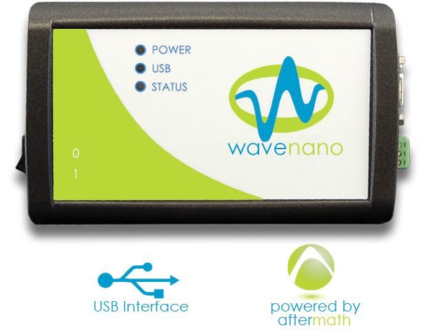 Product Page
Quick Specification Overview
| Working Electrode Channels | 1 |
| Measured Current Ranges | ±1 mA, ±50 µA, ±2 μA, ±100 nA |
| Autoranging | Yes |
| Practical Current Range | 20 pA to 1 mA |
| ADC Input | 16 bits |
| Compliance Voltage | ± 12 V |
| Measured Potential Ranges | ±4.0 V |
| CV Sweep Rate (min) | 10 μV / sec (125 μV step every 12.5 sec) |
| CV Sweep Rate (max) | 10 V/sec (10 mV step every 1.0 msec) |
| Point Interval | 500 μsec (minimum) |
| EIS Capable | No |
| EIS Frequency Range | N/A |
| Instrument Dimensions | 165 × 100 × 29 mm (6.5 × 3.9 × 1.1 in) |
| Instrument Weight | 280 g (10 oz.) |
| Interface | USB |
| Wireless Capable | No |
Sense line with driven shield
Drive line with grounded shield
1
Separate sense and drive lines, each with driven shield
(current measurement via passive shunt)
N/A
The DC Common is isolated from the USB port, the instrument chassis, and earth ground. The DC Common is accessible via the Control Port on the back panel.
The instrument chassis terminal is accessible via a banana jack (metal) on the back panel. The GRAY banana plug on the cell cable also provides an instrument chassis connection to allow convenient connection of the instrument chassis to a Faraday cage surrounding the electrochemical cell.
As shipped from the factory, the instrument chassis and DC Common are connected via a green block connector plugged into the Control Port on the back panel. The green block connector intentionally shorts the instrument chassis and DC Common pins; to isolate those ground connections, the user may remove the green block connector from the instrument.
No direct connection to earth ground is provided.
±150 mA, ±5 mA, ±150 μA, ±5 μA, ±150 nA, ±5 nA
4.70 μA, 157 nA, 4.70 nA, 157 pA, 4.70 pA, 157 fA
Yes
1 pA to 150 mA
±0.2% of setting, ±0.05% of range
< 20 fA at 0 VDC, < 130 fA at 5 VDC
N/A
N/A
16 bits
12 Hz, 1 kHz (3-pole, low pass Bessel filters)
±150 mA, ±5 mA, ±150 μA, ±5 μA, ±150 nA, ±5 nA
4.70 μA, 157 nA, 4.70 nA, 157 pA, 4.70 pA, 157 fA
±0.2% of setting, ±0.05% of range
16 bits
±150 mA (maximum)
160 mA, all ranges
> ±11 V
> 30 kHz (on fastest speed setting)
undertermined
180 V/ms (potentiostatic mode, on fastest speed setting)
800 V/ms (galvanostatic mode, on fastest speed setting)
> 1013 Ω in parallel with 7 pF
6 fA leakage/bias current typical, < 100 fA max at 25°C
> 73 dB 0 – 100 Hz
> 60 dB ≤ 1 kHz
> 39 dB ≤ 10 kHz
> 800 kHz (3 dB)
±8.0 V
250 μV per ADC bit
±0.2% of setting, ±0.05% of range
16 bits
12 Hz, 1 kHz (3-pole, low pass Bessel filters)
±8.0 V
250 μV per DAC bit
±0.2% of setting, ±0.05% of range, ±1.0 mV
16 bits
10 μV/s (469 μV step per 46.9 s, 313 μV step per 31.3 s, or 78 μV per 7.8 s)
10 V/sec (10 mV step every 1.0 ms)
500 ns (minimum time base)
1 ms (minimum)
Simultaneous current & potential input
<10 million per experiment
No
N/A
N/A
N/A
N/A
N/A
N/A
N/A
N/A
N/A
4-pin connector includes chassis ground, rotator enable output signal (+15 V tolerant), analog signal ground (DC Common), and analog rotation rate control output signal
±10.0 V
Open drain with 4.7 kΩ pull up to +4 V (TTL compatible)
External dummy cell (included)
HD-15 male connector to multiple banana plugs via shielded coaxial cables (included)
N/A
N/A
N/A
N/A
N/A
N/A
N/A
N/A
N/A
N/A
5.0 VDC, 2 A (low voltage DC device)
Input Requirements: 100 to 240 VAC, 0.5 A, 50 to 60 Hz
Output Power: 5 VDC, 2.0 A
Power supply (included) has a C14 type input connector
Various international cables sold separately (C13 type)
Power, USB/wireless connection, status, and overload
55 × 170 × 130 mm (2.17 × 6.69 × 5.12 in)
0.6 kg (1.25 lb)
305 × 254 × 102 mm (12 × 10 × 4 in)
1.8 kg (4 lb)
10°C – 40°C
80% RH maximum, non-condensing
Wireless or USB
Yes
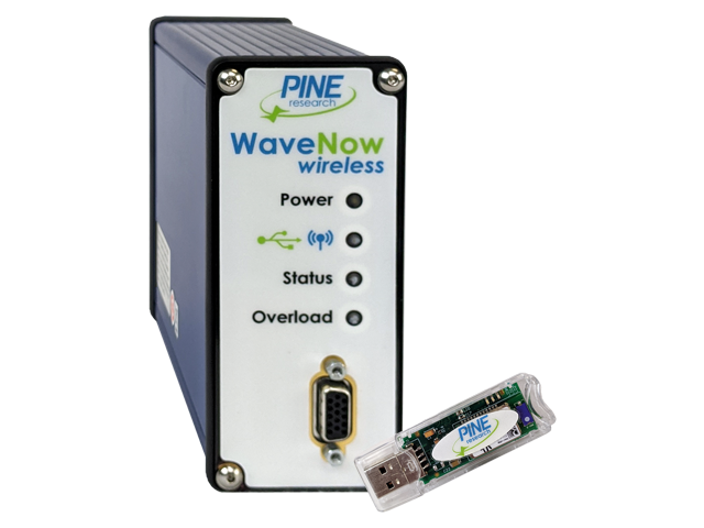 Product Page
Quick Specification Overview
| Working Electrode Channels | 1 |
| Measured Current Ranges | ±150 mA, ±5 mA, ±150 μA, ±5 μA, ±150 nA, ±5 nA |
| Autoranging | Yes |
| Practical Current Range | 1 pA to 150 mA |
| ADC Input | 16 bits |
| Compliance Voltage | > ±11 V |
| Measured Potential Ranges | ±8.0 V |
| CV Sweep Rate (min) | 10 μV/s (469 μV step per 46.9 s, 313 μV step per 31.3 s, or 78 μV per 7.8 s) |
| CV Sweep Rate (max) | 10 V/sec (10 mV step every 1.0 ms) |
| Point Interval | 1 ms (minimum) |
| EIS Capable | No |
| EIS Frequency Range | N/A |
| Instrument Dimensions | 55 × 170 × 130 mm (2.17 × 6.69 × 5.12 in) |
| Instrument Weight | 0.6 kg (1.25 lb) |
| Interface | Wireless or USB |
| Wireless Capable | Yes |
Sense line with driven shield
Drive line
1
Separate sense and drive lines, each with driven shield
(current measurement via passive shunt)
N/A
The DC Common is accessible via the black banana plug on the cell cable and the center pin on the Rotator Control Port
The metal case (chassis) is connected to the shield on the Cell Port and the shield on the USB Port. As shipped from the factory, the instrument chassis and DC Common are connected. A jumper on the circuit board may be removed to allow the DC Common to float with respect to the chassis.
No direct connection to earth ground is provided. The chassis may (either intentionally or unknowingly) be connected to earth ground via a USB cable connected to a remote computer.
±100 mA, ±5 mA, ±200 μA, ±10 μA
3.4 μA, 170 nA, 6.8 nA, 340 pA
Yes
1 nA to 100 mA
±0.2% of setting, ±0.05% of range
10 pA at 25˚C
N/A
N/A
16 bits
2.5 kHz (2-pole, low pass filter)
±100 mA, ±5 mA, ±200 μA, ±10 μA
3.1 μA, 156 nA, 6.25 nA, 313 pA
±0.2% of setting, ±0.05% of range
16 bits
±100.0 mA (maximum)
undetermined
±12 V
> 20 kHz (on “fast” speed setting)
undertermined
180 V/msec (on “fast” speed setting)
> 10^14 Ω in parallel with < 20 pF
< 2 pA leakage/bias current at 25°C
> 50 dB at 10 kHz, 80 dB at 60 Hz
> 800 kHz (3 dB)
±10.0 V
340 μV per DAC bit
±0.2% of setting, ±0.05% of range
16 bits
2.5 kHz (2-pole, low pass filter)
±10.0 V
312.5 μV per DAC bit
±0.2% of setting, ±1.0 mV
16 bits
25 μV/s (312.5 μV step every 12.5 sec)
10 V/sec (10 mV step every 1.0 msec)
500 nsec (minimum time base)
500 μsec (minimum)
Simultaneous Current and Potential
<10 million per experiment
No
N/A
N/A
N/A
N/A
N/A
N/A
N/A
N/A
N/A
3-pin connector includes analog signal ground, digital rotator enable signal, and analog rotation rate control signal
±10.5 V
Open Drain (TTL compatible)
External dummy cell (included)
HD-15 male connector to multiple banana plugs via shielded coaxial cables (included), other designs available
N/A
N/A
N/A
N/A
N/A
N/A
N/A
N/A
N/A
N/A
5.0 VDC, 2 A (low voltage DC device)
100 to 240 VAC, 300 mA, 50 to 60 Hz
Various International Cables Sold Separately (C13 type)
Power, USB, and status
165 × 100 × 29 mm
(6.5 × 3.9 × 1.1 in)
280 g (10 oz.)
260 × 260 × 360 mm
(10.2 × 10.2 × 14.2 in.)
1.4 kg (3 lb)
10°C – 40°C
80% RH maximum, non-condensing
USB
No
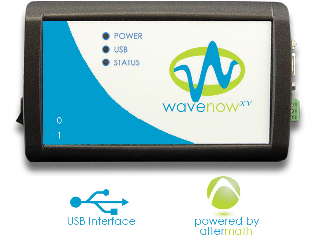 Product Page
Quick Specification Overview
| Working Electrode Channels | 1 |
| Measured Current Ranges | ±100 mA, ±5 mA, ±200 μA, ±10 μA |
| Autoranging | Yes |
| Practical Current Range | 1 nA to 100 mA |
| ADC Input | 16 bits |
| Compliance Voltage | ±12 V |
| Measured Potential Ranges | ±10.0 V |
| CV Sweep Rate (min) | 25 μV/s (312.5 μV step every 12.5 sec) |
| CV Sweep Rate (max) | 10 V/sec (10 mV step every 1.0 msec) |
| Point Interval | 500 μsec (minimum) |
| EIS Capable | No |
| EIS Frequency Range | N/A |
| Instrument Dimensions | 165 × 100 × 29 mm (6.5 × 3.9 × 1.1 in) |
| Instrument Weight | 280 g (10 oz.) |
| Interface | USB |
| Wireless Capable | No |
Sense line with driven shield
Drive line with grounded shield
1
Separate sense and drive lines, each with driven shield
(current measurement via passive shunt)
N/A
The DC Common is isolated from the USB port, the instrument chassis, and earth ground. The DC Common is accessible via the Control Port on the back panel.
The instrument chassis terminal is accessible via a banana jack (metal) on the back panel. The GRAY banana plug on the cell cable also provides an instrument chassis connection to allow convenient connection of the instrument chassis to a Faraday cage surrounding the electrochemical cell.
As shipped from the factory, the instrument chassis and DC Common are connected via a green block connector plugged into the Control Port on the back panel. The green block connector intentionally shorts the instrument chassis and DC Common pins; to isolate those ground connections, the user may remove the green block connector from the instrument.
No direct connection to earth ground is provided.
±1.5 mA, ±50 μA, ±1.5 μA, ±50 nA, ±1.5 nA, ±50 pA
47.0 nA, 1.57 nA, 47.0 pA, 1.57 pA, 47.0 fA, 1.57 fA
Yes
40 fA (with 1 Hz bandwidth) to 1.5 mA (full bandwidth)
±0.2% of reading plus ±0.05% of five upper current ranges; ±0.5% of 50 pA range with ±1 pA offset
< 20 fA at 0 VDC, < 130 fA at 5 VDC
N/A
N/A
16 bits
12 Hz, 1 kHz (3-pole, low pass Bessel filters)
±1.5 mA, ±50 μA, ±1.5 μA, ±50 nA, ±1.5 nA, ±50 pA
47.0 nA, 1.57 nA, 47.0 pA, 1.57 pA, 47.0 fA, 1.57 fA
±0.2% of setting, ±0.05% of range
16 bits
±1.5 mA (maximum)
10 mA, all ranges
> ±11 V
> 30 kHz (on fastest speed setting)
undertermined
180 V/ms (potentiostatic mode, on fastest speed setting)
800 V/ms (galvanostatic mode, on fastest speed setting)
> 1013 Ω in parallel with 7 pF
6 fA leakage/bias current typical, < 100 fA max at 25°C
> 73 dB 0 – 100 Hz
> 60 dB ≤ 1 kHz
> 39 dB ≤ 10 kHz
> 800 kHz (3 dB)
±8.0 V
250 μV per ADC bit
±0.2% of setting, ±0.05% of range
16 bits
12 Hz, 1 kHz (3-pole, low pass Bessel filters)
±8.0 V
250 μV per DAC bit
±0.2% of setting, ±0.05% of range, ±1.0 mV
16 bits
10 μV/s (469 μV step per 46.9 s, 313 μV step per 31.3 s, or 78 μV per 7.8 s)
10 V/sec (10 mV step every 1.0 ms)
500 ns (minimum time base)
1 ms (minimum)
Simultaneous current & potential input
<10 million per experiment
No
N/A
N/A
N/A
N/A
N/A
N/A
N/A
N/A
N/A
4-pin connector includes chassis ground, rotator enable output signal (+15 V tolerant), analog signal ground (DC Common), and analog rotation rate control output signal
±10.0 V
Open drain with 4.7 kΩ pull up to +4 V (TTL compatible)
External dummy cell (included)
HD-15 male connector to multiple banana plugs via shielded coaxial cables (included)
N/A
N/A
N/A
N/A
N/A
N/A
N/A
N/A
N/A
N/A
5.0 VDC, 2 A (low voltage DC device)
Input Requirements: 100 to 240 VAC, 0.5 A, 50 to 60 Hz
Output Power: 5 VDC, 2.0 A
Power supply (included) has a C14 type input connector
Various international cables sold separately (C13 type)
Power, USB/wireless connection, status, and overload
55 × 170 × 130 mm (2.17 × 6.69 × 5.12 in)
0.6 kg (1.25 lb)
305 × 254 × 102 mm (12 × 10 × 4 in)
1.8 kg (4 lb)
10°C – 40°C
80% RH maximum, non-condensing
Wireless or USB
Yes
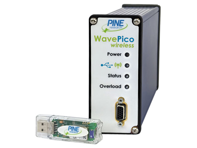 Product Page
Quick Specification Overview
| Working Electrode Channels | 1 |
| Measured Current Ranges | ±1.5 mA, ±50 μA, ±1.5 μA, ±50 nA, ±1.5 nA, ±50 pA |
| Autoranging | Yes |
| Practical Current Range | 40 fA (with 1 Hz bandwidth) to 1.5 mA (full bandwidth) |
| ADC Input | 16 bits |
| Compliance Voltage | > ±11 V |
| Measured Potential Ranges | ±8.0 V |
| CV Sweep Rate (min) | 10 μV/s (469 μV step per 46.9 s, 313 μV step per 31.3 s, or 78 μV per 7.8 s) |
| CV Sweep Rate (max) | 10 V/sec (10 mV step every 1.0 ms) |
| Point Interval | 1 ms (minimum) |
| EIS Capable | No |
| EIS Frequency Range | N/A |
| Instrument Dimensions | 55 × 170 × 130 mm (2.17 × 6.69 × 5.12 in) |
| Instrument Weight | 0.6 kg (1.25 lb) |
| Interface | Wireless or USB |
| Wireless Capable | Yes |
Sense line with driven shield
Drive line with grounded shield
2
Separate sense and drive lines, each with driven shield
(current measurement via passive shunt)
Separate sense and drive lines, each with driven shield
(current measurement via passive shunt)
The signal ground (DC Common) is isolated from the USB port and floats with respect to the instrument chassis and earth ground. The signal ground is accessible via the black banana plug on the cell cable
The metal case (chassis) terminal is a banana binding post (back panel) which may optionally be used to connect the chassis to earth ground or signal ground to improve noise screening (shielding).
No direct connection to earth ground is provided. The chassis may (either intentionally or unknowingly) be connected to earth ground via a USB cable connected to a remote computer.
±1 A, ±100 mA, ±10 mA, ±1 mA, ±100 μA, ±10 μA, ±1 μA, ±100 nA
31.3 μA, 3.13 μA, 313 nA, 31.3 nA, 3.13 nA, 313 pA, 31.3 pA, 3.13 pA
Yes
100 pA to 1.0 A
±0.2% of setting; ±0.05% of range
<10 pA at 25˚C
N/A
N/A
16 bits
10 Hz, 30 Hz, 100 Hz, 1 kHz, 10 kHz (2-pole, low pass Bessel filters)
±1 A, ±100 mA, ±10 mA, ±1 mA, ±100 μA, ±10 μA, ±1 μA, ±100 nA
31.3 μA, 3.13 μA, 313 nA, 31.3 nA, 3.13 nA, 313 pA, 31.3 pA, 3.13 pA
±0.2% of setting; ±0.05% of range
16 bits
±1.0 A (maximum)
undertermined
± 16.5 V
> 200 kHz (on fastest speed setting)
undertermined
10 V/μs (on fastest speed setting)
>1013 Ω in parallel with <10 pF
<10 pA leakage/bias current at 25˚C
>100 dB 0 − 1 kHz; >74 dB at 10 kHz
>11 MHz (3 dB)
±10.0 V, ±2.5 V
313 μV, 78 μV per DAC bit
±0.2% of setting, ±0.05% of range
16 bits
10 Hz, 30 Hz, 100 Hz, 1 kHz, 10 kHz (2-pole, low pass Bessel filters)
±10.0 V, ±2.5 V
313 μV, 78 μV per DAC bit
±0.2% of setting, ±0.05% of range
16 bits
10 μV/s (313 μV step per 31.3 s or 78 μV per 7.8 s)
125 V/s (10 mV step per 1.0 ms)
10 ns (minimum time base)
80 μs (minimum)
Simultaneous sampling of all analog input signals
<10 million per experiment
No
N/A
N/A
N/A
N/A
N/A
N/A
N/A
N/A
7-pin mini circular DIN includes analog and digital signal grounds, digital rotator enable signal, auxiliary digital output signal, and analog rotation rate control signal
3-pin connector includes analog signal ground, digital rotator enable signal, and analog rotation rate control signal
±10.0 V, ±2.5 V
open drain (TTL compatible)
External dummy cell (included)
Combination D-SUB connector to multiple banana plugs via shielded coaxial cables (included)
9-pin DSUB connector includes digital signal ground, two digital output signals, and three digital input signals
BNC female, TTL compatible
BNC female, TTL compatible
BNC female, ±10 V differential input, 20 kΩ impedance, ±0.5% accuracy; allows external waveform to be summed directly to the working electrode excitation signal. K2 Input available only on WaveDriver 20 bipotentiostat.
N/A
N/A
N/A
N/A
N/A
BNC female, ±10 V bipolar output, 313 μV resolution, 0.2% accuracy (available only when second working electrode not in use)
24.0 VDC (±5%), 4.0A (low voltage DC device)
Input Requirements: 100 to 240 VAC, 1.4 to 0.7 A, 50 to 60 Hz
Output Power: 24 VAC, 5.0 A Power supply (included) has a C14 type input connector
Various international cables sold separately (C13 type)
Power, USB, and status
160 × 324 × 255 mm
(6.3 × 12.75 × 10.0 in)
4.6 kg (10.2 lb)
254 × 356 × 457 mm
(10 × 14 × 18 in)
7.7 kg (17 lb)
10 °C – 40 °C
80% RH maximum, non-condensing
USB
No
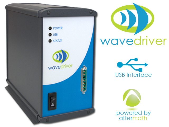 Product Page
Quick Specification Overview
| Working Electrode Channels | 2 |
| Measured Current Ranges | ±1 A, ±100 mA, ±10 mA, ±1 mA, ±100 μA, ±10 μA, ±1 μA, ±100 nA |
| Autoranging | Yes |
| Practical Current Range | 100 pA to 1.0 A |
| ADC Input | 16 bits |
| Compliance Voltage | ± 16.5 V |
| Measured Potential Ranges | ±10.0 V, ±2.5 V |
| CV Sweep Rate (min) | 10 μV/s (313 μV step per 31.3 s or 78 μV per 7.8 s) |
| CV Sweep Rate (max) | 125 V/s (10 mV step per 1.0 ms) |
| Point Interval | 80 μs (minimum) |
| EIS Capable | No |
| EIS Frequency Range | N/A |
| Instrument Dimensions | 160 × 324 × 255 mm (6.3 × 12.75 × 10.0 in) |
| Instrument Weight | 4.6 kg (10.2 lb) |
| Interface | USB |
| Wireless Capable | No |
Sense line with driven shield
Drive line with grounded shield
2
Separate sense and drive lines, each with driven shield
(current measurement via passive shunt)
Separate sense and drive lines, each with driven shield
(current measurement via transimpedance amplifier)
The DC Common is isolated from the USB port, the instrument chassis and earth ground. The DC Common is accessible via a banana binding post (black) on the back panel.
The instrument chassis terminal is accessible via a banana binding post (metal) on the back panel. The GRAY banana plug on the cell cable also provides a chassis connection to allow convenient connection of the instrument chassis to a Faraday cage surrounding the electrochemical cell.
No direct connection to earth ground is provided.
±1 A, ±100 mA, ±10 mA, ±1 mA, ±100 μA, ±10 μA, ±1 μA, ±100 nA
31.3 μA, 3.13 μA, 313 nA, 31.3 nA, 3.13 nA, 313 pA, 31.3 pA, 3.13 pA
Yes
20 pA to 1.0 A
±0.2% of setting; ±0.05% of range
<10 pA at 25˚C
N/A
N/A
16 bits
10 Hz, 30 Hz, 100 Hz, 1 kHz, 10 kHz (2-pole, low pass Bessel filters)
±1 A, ±100 mA, ±10 mA, ±1 mA, ±100 μA, ±10 μA, ±1 μA, ±100 nA
31.3 μA, 3.13 μA, 313 nA, 31.3 nA, 3.13 nA, 313 pA, 31.3 pA, 3.13 pA
±0.2% of setting; ±0.05% of range
16 bits
±1.0 A (maximum)
1 A, 100 mA ranges: < 1.3 A
10 mA −100 nA ranges: < 200 mA
> ±17 V
>2.5 MHz (on fastest speed setting)
< 35 µVRMS in 2 MHz bandwidth
10 V/μs (on fastest speed setting)
>1013 Ω in parallel with <10 pF
<10 pA leakage/bias current at 25˚C
>100 dB 0 − 1 kHz; >74 dB at 10 kHz
>15 MHz (3 dB)
±15.0 V, ±10.0 V, ±2.5 V
469 μV, 313 μV, 78 μV per DAC bit
±0.2% of setting, ±0.05% of range
16 bits
10 Hz, 30 Hz, 100 Hz, 1 kHz, 10 kHz (2-pole, low pass Bessel filters)
±15.0 V, ±10.0 V, ±2.5 V
469 μV, 313 μV, 78 μV per DAC bit
±0.2% of setting, ±0.05% of range
16 bits
10 μV/s (469 μV per 46.9 s, 313 μV step per 31.3 s or 78 μV per 7.8 s)
75 V/s
10 ns (minimum time bar)
80 μs (minimum)
Simultaneous sampling of all analog input signals
<10 million per experiment
No
N/A
N/A
N/A
N/A
N/A
N/A
N/A
N/A
7-pin mini circular DIN includes analog and digital signal grounds, digital rotator enable signal (+15 V max), auxiliary digital output signal, and analog rotation rate control signal
3-pin connector includes analog signal ground, digital rotator enable signal (+15 V max), and analog rotation rate control signal
±10.0 V, ±2.5 V
Open drain with 4.7 kΩ pull up to +5 V (TTL compatible)
External dummy cell (included)
Combination D-SUB connector to multiple banana plugs via shielded coaxial cables (included)
9-pin DSUB connector that includes DC Common, two digital output signals, and two digital input signals
BNC female, TTL compatible
BNC female, TTL compatible
BNC female, ±10 V differential input, 20 kΩ impedance, ±0.5% accuracy; allows external waveform to be summed directly to the working electrode excitation signal
BNC female, ±15 V, ±10 V, ±2.5 V output, ±0.5% accuracy
BNC female, ±10 V output, scaled to current range, ±0.5% accuracy
BNC female, ±15 V, ±10 V, ±2.5 V output, ±0.5% accuracy
BNC female, ±10 V output, scaled to current range, ±0.5% accuracy
BNC female, ±10 V differential input, 313 μV resolution, 0.2% accuracy (available when second working electrode not in use)
BNC female, ±10 V bipolar output, 313 μV resolution, 0.2% accuracy (available when second working electrode not in use)
24.0 VDC (±5%), 5.0 A (low voltage DC device)
Input Requirements: 100 to 240 VAC, 1.4 to 0.7 A, 50 to 60 Hz Output Power: 24 VAC, 5.0 A Power supply (included) has a C14 type input connector
Various international cables sold separately (C13 type)
Power, USB, and status
160 × 324 × 255 mm
(6.3 × 12.75 × 10.0 in)
4.6 kg (10.2 lb)
254 × 356 × 457 mm
(10 × 14 × 18 in)
7.7 kg (17 lb)
10 °C – 40 °C
80% RH maximum, non-condensing
USB
No
 Product Page
Quick Specification Overview
| Working Electrode Channels | 2 |
| Measured Current Ranges | ±1 A, ±100 mA, ±10 mA, ±1 mA, ±100 μA, ±10 μA, ±1 μA, ±100 nA |
| Autoranging | Yes |
| Practical Current Range | 20 pA to 1.0 A |
| ADC Input | 16 bits |
| Compliance Voltage | > ±17 V |
| Measured Potential Ranges | ±15.0 V, ±10.0 V, ±2.5 V |
| CV Sweep Rate (min) | 10 μV/s (469 μV per 46.9 s, 313 μV step per 31.3 s or 78 μV per 7.8 s) |
| CV Sweep Rate (max) | 75 V/s |
| Point Interval | 80 μs (minimum) |
| EIS Capable | No |
| EIS Frequency Range | N/A |
| Instrument Dimensions | 160 × 324 × 255 mm (6.3 × 12.75 × 10.0 in) |
| Instrument Weight | 4.6 kg (10.2 lb) |
| Interface | USB |
| Wireless Capable | No |
Interlock prevents rotation when enclosure window is in raised position. Front panel LED indicates enclosure interlock state.
Optional digital motor stop input signal on external I/O port
Available TTL logic: active high or active low, jumper selectable
Front panel LED indicates when external motor stop is active
100 – 200 RPM: Accurate to within ±2 counts of display reading
200 – 8,000 RPM: Accurate to within ±1% of display reading
10-turn rotation rate control knob on front panel
Optional rate control via input signal on external I/O port
Available control ratios: 1, 2, or 4 RPM/mV, jumper selectable
4 digit display indicates rotation rate (RPM)
Optional rate monitoring via output signal on external I/O port
Output signal ratio: 2 RPM/mV
Push-button toggle on front panel with LED indicators for “pause” and “run”
undetermined
Closed loop servo-system (PWM)
Temperature-compensated tachometer mounted on motor shaft
18.7 mN m
11 W
Motor current is electronically limited
Permanent Magnet
undetermined
Disk electrode: red banana jack on motor unit
Ring electrode: blue banana jack on motor unit
AC Mains: 100 – 240 VAC, ±10%; 50/60 Hz; 2 A
DC Supply: 24 VDC, 1.5 A (included)
Side of unit
Metal banana jack on motor unit
Second connection provided on external I/O port
Connection provided on external I/O port
No direct connection available
Width: 15 in (38 cm)
Depth: 11 in (28 cm)
Height with enclosure window in lower position: 15 in (38 cm)
Clearance required to raise enclosure window: 24 in (61 cm)
Enclosure base and sides: black high-density polyethylene
Enclosure window: clear polycarbonate
Electronics cabinet: black powder-coated aluminum
10°C – 40°C (50°F-104°F)
Shipping weight: 24 lb (11 kg)
Shipping dimensions: 16.0 × 16.0 × 16.0 in (41 × 41 × 41 cm)
E5, E5TQ
E6, E7, E8
N/A
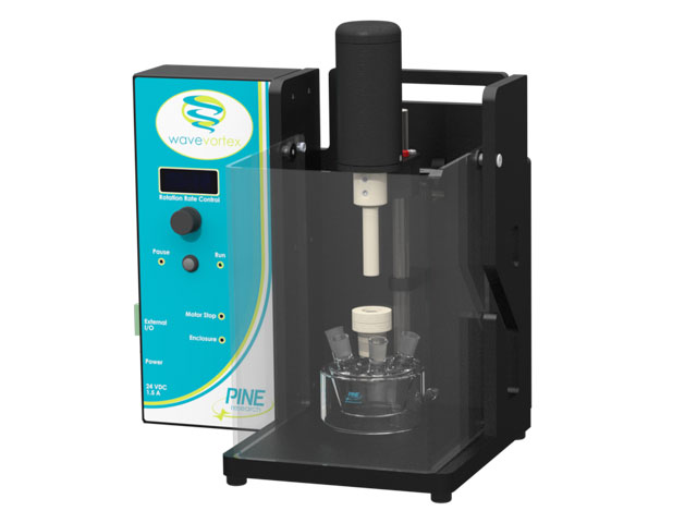 Product Page
Quick Specification Overview
| Rate Accuracy | 100 - 200 RPM: Accurate to within ±2 counts of display reading 200 - 8,000 RPM: Accurate to within ±1% of display reading |
| Rate Control (external) | Optional rate control via input signal on external I/O port Available control ratios: 1, 2, or 4 RPM/mV, jumper selectable |
| Rate Output | Optional rate monitoring via output signal on external I/O port Output signal ratio: 2 RPM/mV |
| Maximum Continuous Torque | 18.7 mN m |
| Motor Power | 11 W |
| Electrode Connections | Disk electrode: red banana jack on motor unit Ring electrode: blue banana jack on motor unit |
| Dimensions | Width: 15 in (38 cm) Depth: 11 in (28 cm) Height with enclosure window in lower position: 15 in (38 cm) Clearance required to raise enclosure window: 24 in (61 cm) |
| Shipping Information | Shipping weight: 24 lb (11 kg) Shipping dimensions: 16.0 × 16.0 × 16.0 in (41 × 41 × 41 cm) |
| Rotating Disk (RDE) | E5, E5TQ |
| Rotating Ring-Disk (RRDE) | E6, E7, E8 |
| Rotating Cylinder (RCE) | N/A |
N/A
Back panel input optional digital motor stop signal (banana jack, control unit back panel)
100 to 200 RPM: Accurate to within ±2 counts of display reading
200 to 10,000 RPM: Accurate to within ±1% of display reading
10-turn rotation rate control knob on control unit front panel
Optional rate control via input signal on control unit front panel
Available control ratios: 1, 2, or 4 RPM/mV, jumper selectable
4 ½ digit display indicates rotation rate (RPM)
Allows optional external monitoring of rotation rate (banana jack, control unit front panel)
Output signal ratio: 1 RPM/mV (±1%)
N/A (only possible under external rate control with software)
> 50 Hz, -1 dB
(at 1000 RPM peak to peak modulation on a 2000 RPM base rate)
Closed loop servo-system
Temperature compensated tachometer mounted on motor shaft
28.3 mN m
15 W
2 Amp thermal-type circuit breaker
current limited power supplies
Permanent Magnet
approximately 300,000 RPM/sec maximum (no load)
Disk electrode: red banana jack on motor unit
Ring electrode: blue banana jack on motor unit
AC Mains: 100 – 240 VAC, ±10%; 50/60 Hz; 2A
Rear of control unit
Metal binding post (banana jack) connects to ground lead of power cord and to control unit chassis, no direct terminal provided
Black banana jack (set of three) on control unit front panel, isolated from earth ground
Metal binding post (banana jack) connects to ground lead of power cord and to control unit chassis
Control unit: 11.4 × 10.1 × 5.75 in (29 × 26 × 15 cm)
Rotator enclosure: 18.8 × 15.5 × 21.0 in (48 × 40 × 54 cm)
Enclosure base and sides: white polyproplyene
Enclosure window: clear polycarbonate
Control Unit: aluminum and blue powder-coated aluminum
10°C – 40°C (50°F-104°F)
Shipping weight: 60 lb (27 kg)
Shipping dimensions: 24.0 × 24.0 × 24.0 in (61 × 61 × 61 cm)
E2, E3, E4TQ, E5, E5TQ
E6, E7, E8
ACQC, E9
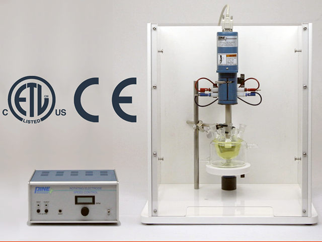 Product Page
Quick Specification Overview
| Rate Accuracy | 100 to 200 RPM: Accurate to within ±2 counts of display reading 200 to 10,000 RPM: Accurate to within ±1% of display reading |
| Rate Control (external) | Optional rate control via input signal on control unit front panel Available control ratios: 1, 2, or 4 RPM/mV, jumper selectable |
| Rate Output | Allows optional external monitoring of rotation rate (banana jack, control unit front panel) Output signal ratio: 1 RPM/mV (±1%) |
| Maximum Continuous Torque | 28.3 mN m |
| Motor Power | 15 W |
| Electrode Connections | Disk electrode: red banana jack on motor unit Ring electrode: blue banana jack on motor unit |
| Dimensions | Control unit: 11.4 × 10.1 × 5.75 in (29 × 26 × 15 cm) Rotator enclosure: 18.8 × 15.5 × 21.0 in (48 × 40 × 54 cm) |
| Shipping Information | Shipping weight: 60 lb (27 kg) Shipping dimensions: 24.0 × 24.0 × 24.0 in (61 × 61 × 61 cm) |
| Rotating Disk (RDE) | E2, E3, E4TQ, E5, E5TQ |
| Rotating Ring-Disk (RRDE) | E6, E7, E8 |
| Rotating Cylinder (RCE) | ACQC, E9 |
Four female DB-25 provides electrode signal lines and power to the electrochemical headstages and supports electrical stimulation (top panel)
Female DB-25 provides digital input lines for external sources (top panel)
Male, two-prong connector receives stimulation current from external source
White lead wire from the electrochemical headstage. See product instructions for details about specialty headstages, such as multiple channel headstages.
Yellow lead wire from the electrochemical headstage. See product instructions for details about specialty headstages, such as multiple channel headstages.
Four
The signal ground is isolated from the power plug and floats with respect to the instrument chassis and earth ground.
The chassis terminal is a banana binding post (back panel) which may optionally be used to connect the chassis to the Faraday cage or to earth ground to improve noise screening (shielding).
Defined by electrochemical headstage, ±200 nA/V (5 MΩ) headstage amplifier included
16-bit resolution (provided by the interface board)
Selectable: low-pass up to 14 kHz, low-pass up to 40 kHz, bandpass (100 Hz to 14 kHz) or bypass (no filtering)
16-bit resolution (provided by the interface board)
±3.3 V (maximum)
100 µV (minimum, as defined by the interface board)
16 bit (as provided by the inerface board)
Selectable: low-pass up to 2 kHz, 5 kHz, or 10 kHz, and bypass (no filtering)
5,000 V/s
±10.0 V (maximum, as defined by interface board)
313 µV (minimum, as defined by the interface baord)
16 bit (as provided by the inerface board)
Up to 20 kHz low-pass filter
±10.0 V (maximum, as defined by interface board)
313 µV (minimum, as defined by the interface baord)
16 bit (as provided by the inerface board)
Up to 5 kHz low-pass filter
500 ns (minimum)
Simultaneous sampling of all analog input signals
>10 million per experiment
External dummy cell (included)
DB-25 to Pine Research electrochemical headstage
200 nA/V (5 MΩ), working driven (other gains available by special order)
White = Reference, Yellow = Working
C14-type socket (includes plug-specific 10 A cord)
Female BNC, Digital, TTL compatible
Female BNC, Digital, TTL compatible
Female BNC, CV frequency, Digital, TTL compatible
Female BNC, Digital, TTL compatible
Female BNC, Flow cell trigger, Digital, TTL compatible
Female BNC, Timing trigger, TTL compatible
Female BNC, Stimulus waveform, Analog, Max ±10.0 V
Female BNC, External stimulus to headstage input; Analog, BNC female
Female DB-25 connector for recording up to 15 TTL signals
68 –pin VHDCI male connector
68 –pin VHDCI male connector
National Instruments PCIe-6363 (sold separately)
National Instruments SHC8-68 EPM x 2
Industry standard LabVIEW based software available to researchers (not provided)
12.0 VDC (±5%)
Input: 100 – 240 VAC, 2.3 A, 50 – 60
Output: 12.0 VDC, 2.5 A
Various international cables available (10 A, C13 Connector)
Power, input and output filter selection, trigger activity
58 × 245 × 295 mm (2.25 × 9.7 × 11.6 in)
2.0 kg (1.8 lb)
10°C to 40°C
80% RH maximum, non-condensing
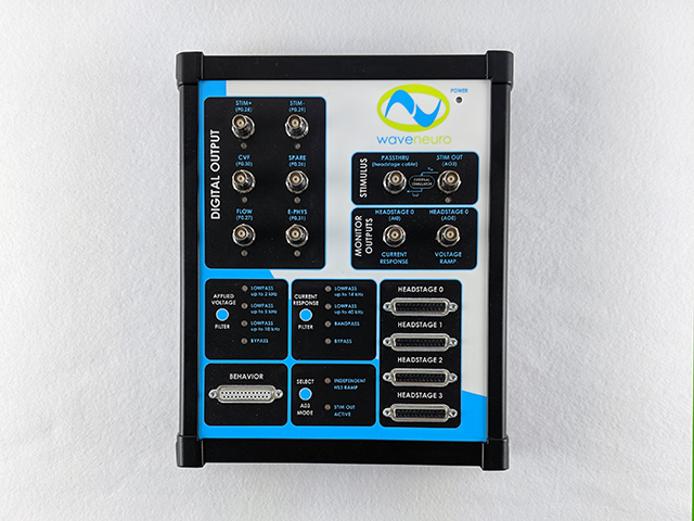 Product Page
Quick Specification Overview
| Headstage Connector | Four female DB-25 provides electrode signal lines and power to the electrochemical headstages and supports electrical stimulation (top panel) |
| Behavioral Connector | Female DB-25 provides digital input lines for external sources (top panel) |
| Stimulus Connector | Male, two-prong connector receives stimulation current from external source |
| Reference Electrode | White lead wire from the electrochemical headstage. See product instructions for details about specialty headstages, such as multiple channel headstages. |
| Working Electrode | Yellow lead wire from the electrochemical headstage. See product instructions for details about specialty headstages, such as multiple channel headstages. |
| Working Electrode Channels | Four |
| Measured Current Range | Defined by electrochemical headstage, ±200 nA/V (5 MΩ) headstage amplifier included |
| Ranges | ±3.3 V (maximum) |
| Resolution | 100 µV (minimum, as defined by the interface board) |
| CV Scan Rate (max) | 5,000 V/s |
| Ranges | ±10.0 V (maximum, as defined by interface board) |
| Point Interval | 500 ns (minimum) |
| Headstage Amplifier | 200 nA/V (5 MΩ), working driven (other gains available by special order) |
| Electrode Connections | White = Reference, Yellow = Working |
| Compatible DAQ Interface | National Instruments PCIe-6363 (sold separately) |
| Control Software | Industry standard LabVIEW based software available to researchers (not provided) |
| Instrument Weight | 2.0 kg (1.8 lb) |
Female DB-25 provides electrode signal lines and power to the electrochemical headstage and supports electrical stimulation (top panel)
Female DB-25 provides digital input lines for external sources (top panel)
Male, two-prong connector receives stimulation current from external source
White lead wire from the electrochemical headstage
Yellow lead wire from the electrochemical headstage
One
The signal ground is isolated from the power plug and floats with respect to the instrument chassis and earth ground.
The chassis terminal is a banana binding post (back panel) which may optionally be used to connect the chassis to earth ground to improve noise screening (shielding)
Defined by electrochemical headstage, ±200 nA/V (5 MΩ) headstage amplifier included
16-bit resolution (provided by the interface board)
Selectable: low-pass up to 14 kHz, low-pass up to 40 kHz, bandpass (100 Hz to 14 kHz) or bypass (no filtering)
16-bit resolution (provided by the interface board)
±3.3 V (maximum)
100 µV (minimum, as defined by the interface board)
16 bit (as provided by the inerface board)
Selectable: low-pass up to 2 kHz, 5 kHz, or 10 kHz, and bypass (no filtering)
5,000 V/s
±10.0 V (maximum, as defined by interface board)
313 µV (minimum, as defined by the interface baord)
16 bit (as provided by the inerface board)
Up to 20 kHz low-pass filter
±10.0 V (maximum, as defined by interface board)
313 µV (minimum, as defined by the interface baord)
16 bit (as provided by the inerface board)
Up to 5 kHz low-pass filter
500 ns (minimum)
Simultaneous sampling of all analog input signals
>10 million per experiment
External dummy cell (included)
DB-25 to Pine Research electrochemical headstage
200 nA/V (5 MΩ), working driven (other gains available by special order)
White = Reference, Yellow = Working
C14-type socket (includes plug-specific 10 A cord)
Female BNC, Digital, TTL compatible
Female BNC, Digital, TTL compatible
Female BNC, CV frequency, Digital, TTL compatible
Female BNC, Digital, TTL compatible
Female BNC, Flow cell trigger, Digital, TTL compatible
Female BNC, Timing trigger, TTL compatible
Female BNC, Stimulus waveform, Analog, Max ±10.0 V
Female BNC, External stimulus to headstage input; Analog, BNC female
Female DB-25 connector for recording up to 15 TTL signals
68 –pin VHDCI male connector
68 –pin VHDCI male connector
National Instruments PCIe-6363 (sold separately)
National Instruments SHC8-68 EPM x 2
Industry standard LabVIEW based software available to researchers (not provided)
12.0 VDC (±5%)
Input: 100 – 240 VAC, 2.3 A, 50 – 60
Output: 12.0 VDC, 2.5 A
Various international cables available (10 A, C13 Connector)
Power, input and output filter selection, trigger activity
58 × 245 × 295 mm (2.25 × 9.7 × 11.6 in)
2.0 kg (1.8 lb)
10°C to 40°C
80% RH maximum, non-condensing
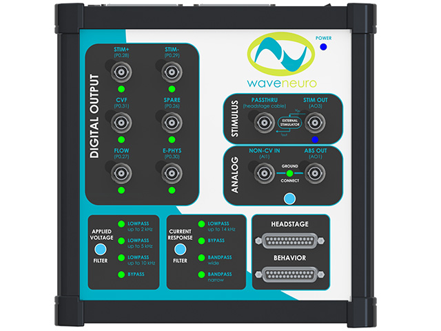 Product Page
Quick Specification Overview
| Headstage Connector | Female DB-25 provides electrode signal lines and power to the electrochemical headstage and supports electrical stimulation (top panel) |
| Behavioral Connector | Female DB-25 provides digital input lines for external sources (top panel) |
| Stimulus Connector | Male, two-prong connector receives stimulation current from external source |
| Reference Electrode | White lead wire from the electrochemical headstage |
| Working Electrode | Yellow lead wire from the electrochemical headstage |
| Working Electrode Channels | One |
| Measured Current Range | Defined by electrochemical headstage, ±200 nA/V (5 MΩ) headstage amplifier included |
| Resolution | 16-bit resolution (provided by the interface board) |
| Ranges | ±3.3 V (maximum) |
| Resolution | 100 µV (minimum, as defined by the interface board) |
| CV Scan Rate (max) | 5,000 V/s |
| Ranges | ±10.0 V (maximum, as defined by interface board) |
| Point Interval | 500 ns (minimum) |
| Headstage Amplifier | 200 nA/V (5 MΩ), working driven (other gains available by special order) |
| Electrode Connections | White = Reference, Yellow = Working |
| Compatible DAQ Interface | National Instruments PCIe-6363 (sold separately) |
| Control Software | Industry standard LabVIEW based software available to researchers (not provided) |
| Instrument Weight | 2.0 kg (1.8 lb) |


