
1. Technique Overview
Many techniques used in electroanalytical chemistry affect change within a chemical system with small surface area to volume ratios. For example, it is common to conduct stationary cyclic voltammetry (CV) at a 3 mm OD working electrode in 100 mL of solution containing 1 mM electroactive species. In such a system, CV can be performed for long periods of time without appreciably changing the bulk concentration of analyte (oxidized and or reduced species), assuming a nominal 1 mA/cm2 current density. In this case, <1 C passes and the bulk concentration of electroactive species does not appreciably change (~250 mC). In contrast to this typical setup, Bulk Electrolysis (BE) is conducted with large surface area to volume ratios and often convective stirring for enhanced mass transport. The anticipated outcome is to significantly change bulk solution properties during the course of the electrolysis. Unlike typical CV experiments, BE working and counter electrodes are 2 – 4 orders of magnitude larger in area; thus, for a larger working electrode with A = 100 cm2 and the same 1 mA/cm2 current density, >350 C passes through the cell. In this case, all electroactive species in the cell are converted to their reduced form in a short period of time. Often, this is the goal to exhaustively convert analyte from reduced to oxidized form, and vice-versa.
Bulk electrolysis is often performed in a separated cell, consisting of either two or three chambers, each separated by a porous material like sintered glass disks (frits) or polymer exchange membranes (e.g., Nafion®). The working and reference electrodes are often placed into one chamber of a separated cell and the counter electrode in another. The working electrode chamber should be stirred to provide maximum mass transport to the electrode during electrolysis. Some electrolysis cells separate each electrode into their own separate chamber. Both the working and counter electrodes should have a large surface area (typically platinum meshes or high surface area carbon meshes, foam, felts and vitreous carbon materials) to increase current (charge) and reduce time to reach exhaustive electrolysis.
Bulk electrolysis can be operated with four different electrode modes:
- controlled potential (POT), where a constant potential is applied and current vs. time is measured
- controlled current (GAL), where a constant current is applied and potential vs. time is measured
- zero resistance ammeter (ZRA), where potential is actively driven to 0 V and current vs. time is measured
- open circuit potential (OCP), where the counter electrode is bypassed such that no current passes and voltage vs. time is measured
Controlled potential bulk electrolysis is by far the most commonly used mode; however, some might use controlled current for select applications. While a potentiostat, with reference feedback, is required for controlled potential bulk electrolysis, simpler instrumentation consisting of only a high voltage power supply (or batteries) and a large resistor can be used. The focus of this article will primarily focus on BE in POT mode (constant potential bulk electrolysis).
2. Fundamental Equations
We will provide a basic description of bulk electrolysis, however the following reference material can be helpful for understanding bulk electrolysis1-3. Consider a reaction
 (1)
(1)where O is reduced to R in a one-electron reaction. A solution of m moles of O would require n moles of electrons to completely reduce O to R. Upon applying a sufficient reducing potential, a large amount of O is converted to R and subsequently swept away from the electrode by stirring. As more O is converted to R the current falls off exponentially until it reaches background level. It is at this point, the electrolysis can be stopped. The charge (Q) passed during the experiment can be obtained by integrating the current with respect to time.
 (2)
(2)The charge can then be converted to the number of moles m of species O using the equation
 (3)
(3)where F is Faraday’s constant (96,485 C•mol-1), and n is the number of electrons transferred during the reaction.
3. Experimental Setup in AfterMath
To perform a bulk electrolysis experiment in AfterMath, choose Bulk Electrolysis (BE) from the Experiments menu (see Figure 1).
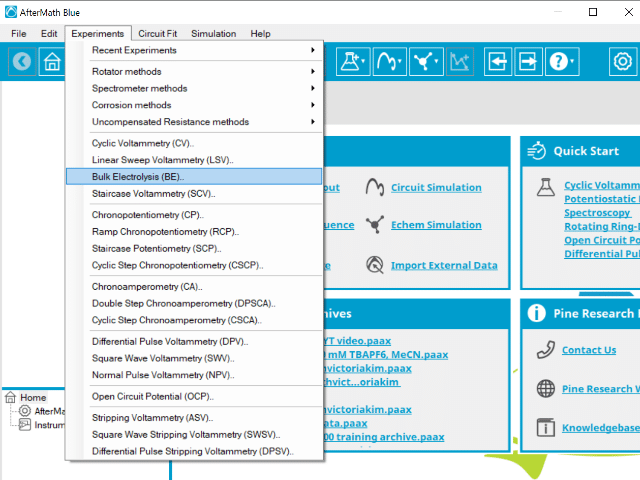
Figure 1: Insertion of a Bulk Electrolysis experiment from the Experiments menu in AfterMath.
Doing so creates an entry within the archive, called BE Parameters. In the right pane of the AfterMath application, several tabs will be shown (see Figure 2).
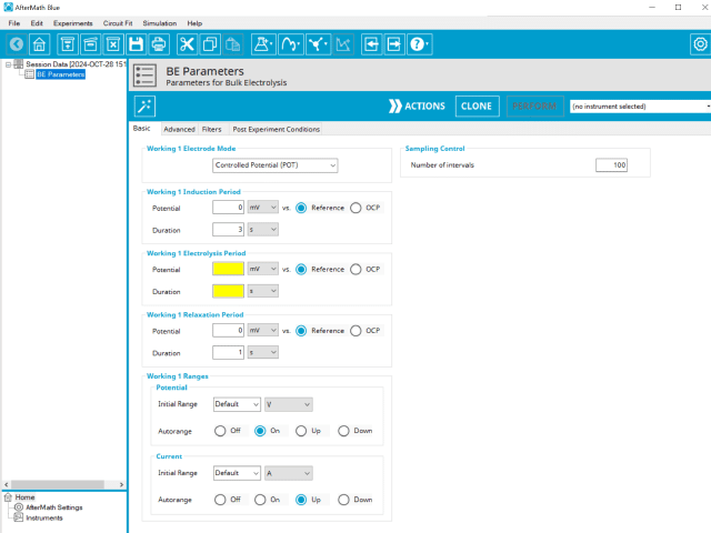
Figure 2: Creating a Bulk Electrolysis Experiment in an AfterMath archive.
As with most Aftermath methods, the experiment sequence is
Induction Period → Electrolysis Period → Relaxation Period → Post-Experiment Idle Conditions
Unlike most experiments, the Induction and Relaxation Periods are on the Basic Tab. The parameters for a BE experiment are fairly simple compared to other methods in AfterMath.
In general, enter minimum required parameters on the Basic tab and press “Perform” to run an experiment. AfterMath will perform a quick audit of the parameters you entered to ensure their validity and appropriateness for the chosen instrument, followed by the initiation of the experiment. In some cases, users may desire to adjust additional settings such as filters, post- experiment conditions, and post-experiment processing before clicking the “Perform” button. Continue reading for detailed information about the fields on each unique tab.
3.1. Basic Tab
The basic tab contains fields for the fundamental parameters necessary to perform a BE experiment. AfterMath shades fields with
yellow when a required entry is blank and shades fields pink when the entry is invalid (see Figure 3).

Figure 3: Bulk Electrolysis (BE) Basic Tab in AfterMath
The first selection with Bulk Electrolysis is the Electrode mode (see Figure 3). Controlled potential BE is the most commonly used mode. The modes available are summarized as follows:
- controlled potential (POT), where a constant potential is applied and current vs. time is measured
- controlled current (GAL), where a constant current is applied and potential vs. time is measured
- zero resistance ammeter (ZRA), where potential is actively driven to 0 V and current vs. time is measured
- open circuit potential (OCP), where the counter electrode is bypassed such that no current passes and voltage vs. time is measured
During the induction period, a set of initial conditions are applied to the electrochemical cell and the cell equilibrates at these conditions. Data are not collected during the induction period, nor are they shown on the plot during this period.
After the induction period, the potential applied to the working electrode is stepped to the specified value for the duration of the experiment, which is called the electrolysis period. The potentiostatic circuit of the instrument maintains constant applied potential relative to the reference electrode while simultaneously measuring the current at the working electrode. During the electrolysis period, potential and current at the working electrode are recorded at regular intervals as specified on the Basic tab. Sampling control defines the number of intervals (number of data points) collected during the electrolysis period. With Electrolysis period duration, a sampling rate can be defined as,

Users should enter a number of intervals that their analysis requires. Commonly, BE experiments are sampled at a lower rate (1 sample/s). Not all sampling rates are allowed due to differences in hardware (WaveNow series vs. WaveDriver series, for example).
The Electrode Range group contains the initial current and potential range fields. These field settings within the Electrode Range group explicitly define the initial current and/or potential ranges used by the potentiostat during the experiment. Additionally, a field for Autorange control for both potential and current appear on this tab. Autorange employs algorithms to adjust the current and potential ranges, as needed, to the most appropriate ranges available to match the measured signal(s). More information on autorange is available elsewhere on the knowledgebase.
The experiment concludes with a relaxation period. During the relaxation period, a set of final conditions (specified on the Advanced tab) are applied to the electrochemical cell and the cell equilibrates at these conditions. Data are not collected during the induction period, nor are they shown on the plot during this period.
At the end of the relaxation period, the post-experiment idle conditions are applied to the cell, and the instrument returns to the idle state. The default plot generated from the data depends on the Electrode Mode selected on the Basic tab (see Figure 3).
A plot of the typical experiment sequence, containing labels of the fields on the Basic tab, helps to illustrate the sequence of events in a BE experiment (see Table 1 and Figure 4). Again, given that different electrode modes are possible, the illustrations provided here assume controlled potential (POT) mode; however, other modes such as controlled current (GAL) are analogous to these figures, with different units on the y-axis.


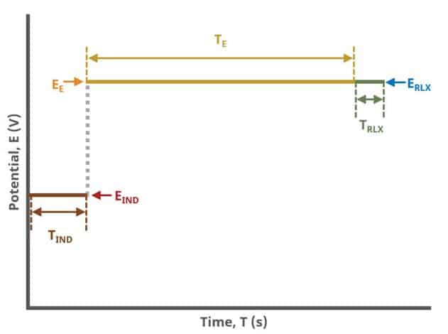
Figure 4: Bulk Electrolysis (BE) Basic Tab Field Diagram
3.2. Advanced Tab
The BE Advanced tab contains two groups for iR Compensation and for Experiment End Trigger (see Figure 5).
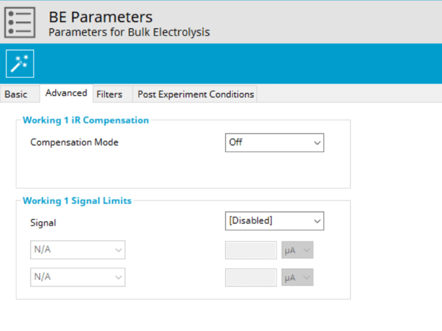
Figure 6: Bulk Electrolysis (BE) Advanced Tab
Detailed description of the iR compensation is provided elsewhere on our website. This mode is used to correct for uncompensated resistance in the electrochemical cell.
In a BE experiment, the researcher may want to have AfterMath monitor the response and then stop the experiment at a specific current, potential, and/or charge. This value is called a trigger and is set in the Experiment End Trigger group on the Advanced tab (see Figure 5). For BE, the signals for the trigger can be potential, current, or charge based on the Electrode Mode selected on the Basic tab (see Figure 3). A common example of using this trigger is in the charging of a battery. A researcher would charge the battery by performing a BE Controlled Current (GAL) mode selected (also called a CC or constant current) with the trigger set to its upper potential limit (e.g., 100% SOC). Once this potential limit is reached, the BE experiment terminates and retains the data collected up to the trigger endpoint.
Another application is in the plating process. If a user wishes to control the deposition layer thickness on a working electrode, they might use a constant potential to drive the reduction at the electrode. In this case, a user may have calculated a theoretical mass they intend to plate to an electrode. Through Faraday’s Law (see Section 2), the user can calculate the total charge that must pass to yield the desired mass on the electrode surface. In this case, a user may set an Experiment End Trigger to stop BE after passing this amount of charge.
3.3. Filters and Post Experimental Conditions Tabs
In nearly all cases, the groups of fields on the Ranges tab are already present on the Basic tab. The Ranges tab shows an Electrode Range group and depending on the experiment shows either, or both, current and potential ranges and the ability to select an autorange function. The fields on this tab are linked to the same fields on the Basic tab (for most experiments). Changing the values on either the Ranges tab or on the Basic tab changes the other set. In other words, the values selected for these fields will always be the same on the Ranges tab and on the Basic tab. More on ranges is found within the knowledgebase,
as is for autorange.
The Filters tab provides access to potentiostat hardware filters, including stability, excitation, current response, and potential response filters. Pine Research recommends that users contact us for help in making changes to hardware filters. Advanced users may have an easier time changing the automatic settings on this tab.
By default, the potentiostat disconnects from the electrochemical cell at the end of an experiment. There are other options available for what these post-experiment conditions can be and are controlled by setting options on the Post Experiment Conditions tab.
4. Sample Experiment
The principal result from a potentiostatic bulk electrolysis is a plot of current versus time (see Figure 6). These data were obtained with the following experimental conditions: 25 mL of cobalt bis(terpyridine) hexafluorophosphate [Co(tpy)2]]PF6]2 in 0.1 M TBAPF6, graphite rod working electrode and graphite rod counter electrode, Electrolysis Potential = -1.7 V.
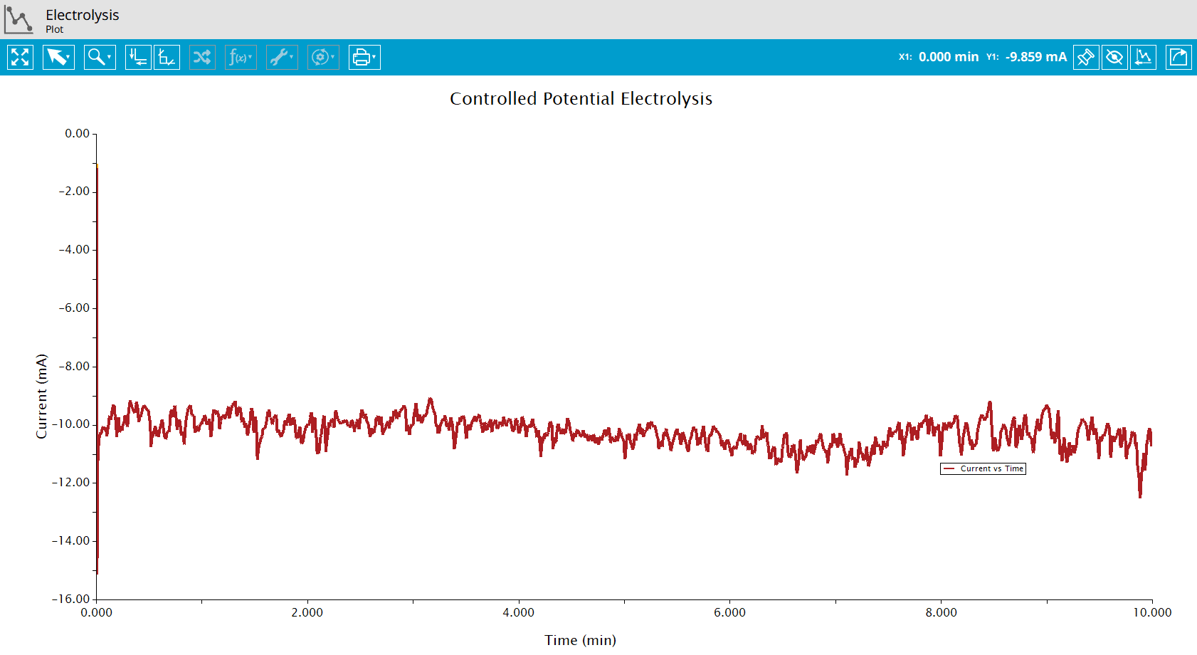
Figure 6: Bulk Electrolysis (BE) of [Co(tpy)2]]PF6]2 reduction.
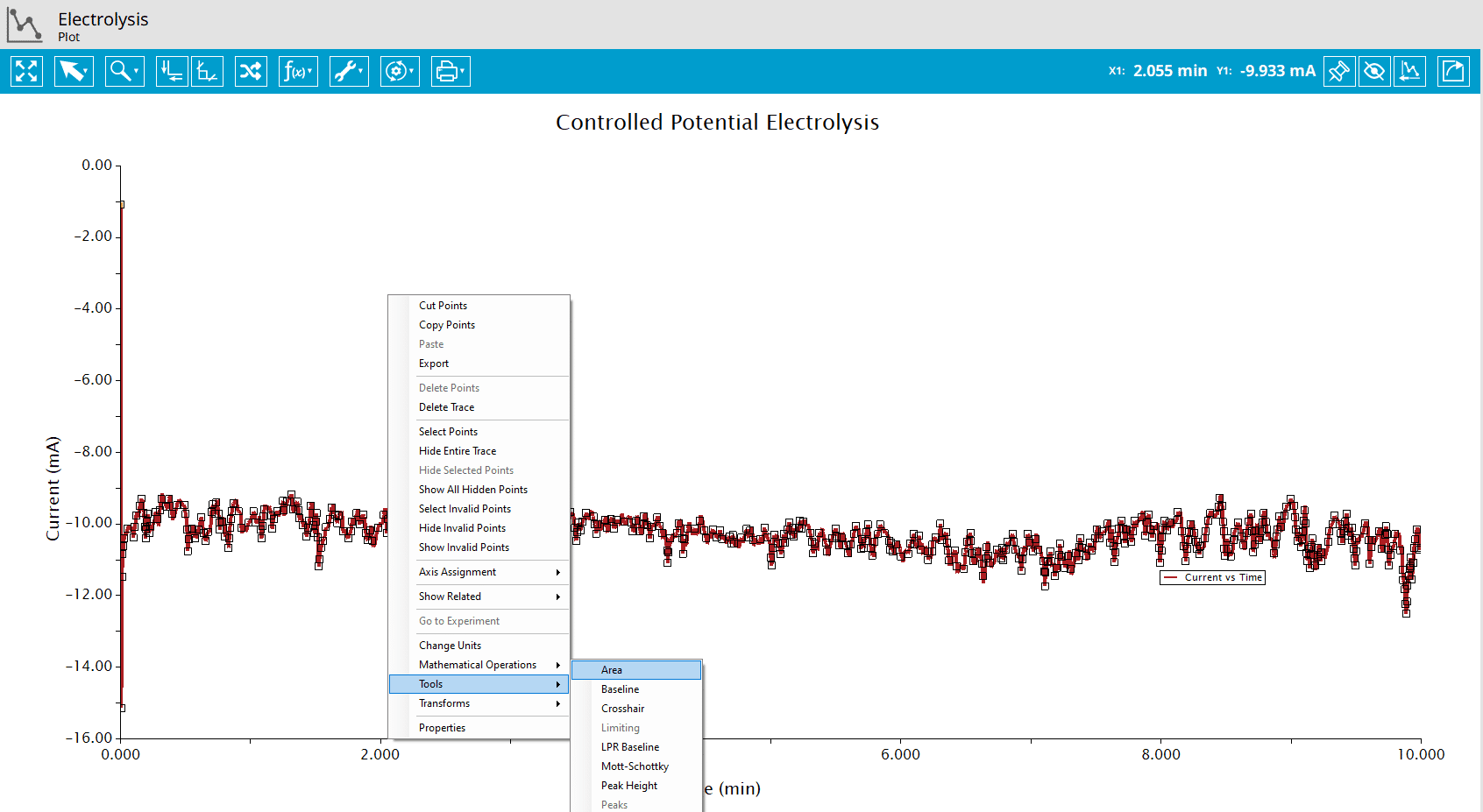
Figure 7: Add Area (integration) tool to a plot in AfterMath.
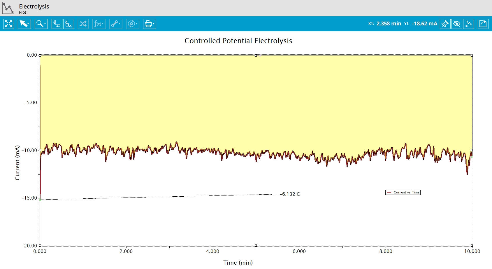
Figure 8: Use of the Area Tool to Find Charge from a BE Experiment.
As shown, for this experiment, Q=-6.132 C (see Figure 8). From Faraday’s Law (see Section 2), the number of moles electrolyzed during the experiment can be determined as follows:

Dividing by the volume of solution, the concentration of [Co(tpy)2]]PF6]2 electrolyzed was

5. Applications from Literature
There are numerous research and industrial applications of bulk electrolysis. Common applications include
- extraction of metals
- electroplating
- refining of metals
- electrocleaning
- production of chemicals
This example illustrates how bulk electrolysis can be used for quantification. Wolfe and coworkers4 electrolyzed solutions of gold nanoparticles passivated with a layer of 6-(ferrocenyl) hexanethiol. Typically, quantitation of the number of ligands protecting a nanoparticle is accomplished through the use of thermogravimetric analysis (TGA). However, since ferrocene sublimes easily, TGA was inconclusive. The researchers quantified the number of ligands by using solutions of known nanoparticle concentration and oxidizing ferrocene to ferrocenium. By determining the charge passed during the experiment, they calculated the number of ligands per nanoparticle. This example highlights how electrochemical techniques, such as bulk electrolysis, can be used in places where traditional techniques might fail.
In work by Surendranath and coworkers5, bulk electrolysis was employed to deposit a film of cobalt-based water oxidation catalysts. The researchers oxidized Co2+ to Co3+ in the presence of various electrolyte solutions. Co3+ reacts with the electrolytes, forming a thin film of particles on an ITO electrode. Complete electrolysis of the solution was not necessary to form the films that were later used as water oxidation catalysts. As this research highlights, bulk electrolysis need not be solely used to exhaustively oxidize or reduce a species in solution. Rather, partial electrolysis was sufficient to produce thin films.
As described in the article by Blattes and coworkers6, bulk electrolysis can be useful for chemical synthesis. Bulk electrolysis was used to simultaneously generate cycloaddition partners for inverse-electron demanding Diels-Alder reactions. Inverse-electron demanding Diels-Alder reactions have not been used as extensively as the normal Diels-Alder reaction due to the limited availability of readily accessible simple electron-deficient dienes. Using bulk electrolysis, the researchers were able to access two unstable entities in situ for use in cycloaddition reactions. The researchers were even able to show regiospecificity and diastereospecificity in the case of heterocyclic annulations.
As a fundamental experimental method of electrochemistry, bulk electrolysis can be easily incorporated into early undergraduate laboratory curricula. Chuan and Chyan7 used screen-printed electrodes to examine the metal-deposition process through bulk electrolysis. Often, experimental electrochemistry is introduced to students in higher level chemistry courses when students have had more time to develop essential lab skills. By using screen-printed electrodes instead of traditional (and expensive) inlaid disk electrodes, the labor-intensive step of electrode preparation (i.e., polishing) is removed. Using a variety of deposition solutions, students can generate layers of different, visually-attractive films in one lab period. Along with the introduction of Faraday’s Law, the researchers are also able to introduce electrodeposition efficiency and concepts of gravimetry since these electrodes can be weighed after the deposition process, providing an introduction to gravimetric analysis. This example provides an excellent way to get students excited about the fascinating world of electrochemistry. Pine Research offers a laboratory exercise based on this application.
6. References
- Zoski, C. G.; Leddy, J.; Bard, A. J.; Electrochemical Methods: Fundamentals and Applications (Student Solutions Manual), 2nd ed. John Wiley: New York, 2002.
- Kissinger, P.; Heineman, W. R. Laboratory Techniques in Electroanalytical Chemistry, 2nd ed. Marcel Dekker, Inc: New York, 1996.
- Wang, J. Analytical Electrochemistry, 3rd ed. John Wiley & Sons, Inc.: Hoboken, NJ, 2006.
- Wolfe, R. L.; Balasubramanian, R.; Tracy, J. B.; Murray, R. W. Fully Ferrocenated Hexanethiolate Monolayer-Protected Gold Clusters. Langmuir, 2007, 23(4), 2247-2254.
- Surendranath, Y.; Dincǎ, M.; Nocera, D. G. Electrolyte-Dependent Electrosynthesis and Activity of Cobalt-Based Water Oxidation Catalysts. J. Am. Chem. Soc., 2009, 131(7), 2615-2620.
- Blattes, E.; Fleury, M.; Largeron, M. Simultaneously Electrogenerated Cycloaddition Partners for Regiospecific Inverse-Electron-Demand Diels−Alder Reactions: A Route for Polyfunctionalized 1,4-Benzoxazine Derivatives. J. Org. Chem., 2004, 69(3), 882-890.
- Chuan, Y.; Chyan, O. Metal Electrodeposition on an Integrated, Screen-Printed Electrode Assembly. J. Chem. Educ., 2008, 85(4), 565.