
1. Introduction
The Rotating Ring-Disk Electrode (RRDE) is uniquely capable of providing fundamental kinetic information regarding fuel cell electrocatalysts. Catalysts for the oxygen reduction reaction (ORR) are of particular interest and are widely used in  fuel cells based on polymer electrolyte membranes. [] Because ORR electrocatalysts typically make use of very expensive metal particles (most notably, nanoscale structures involving platinum), a key issue in fuel cell research is the search for lower cost catalyst materials.
Investigators from a wide variety of backgrounds are bringing their efforts to bear on this economic issue, developing catalytic materials with less noble metal content (i.e., a dilution approach) and/or a more efficient use of the existing noble metal content (i.e., engineering particle morphology). Regardless of the approach taken, these researchers generally end up producing a large number of candidate ORR catalysts which must be screened. The two screening criteria of most interest are the ORR kinetics (which should be as fast as possible) and the amount of peroxide formed (which should be as low as possible). Rotating electrodes [] provide a convenient and well-established way to probe both criteria.
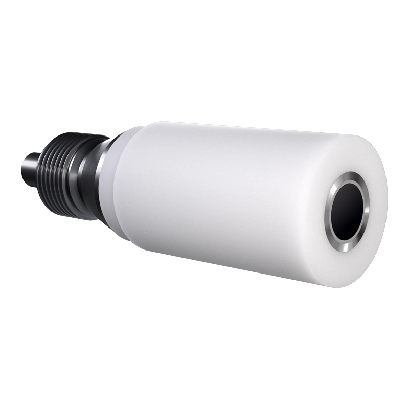
For over fifty years [], Pine Research has provided electrochemical researchers with a reliable line of rotating electrode products. Both our rotating disk (RDE) and rotating ring-disk (RRDE) electrodes (see Figures 1 and 2) have proven to be quite popular tools for probing electrocatalyst behavior. This technical note assimilates much of the practical feedback that we have received from fuel cell researchers who use our products to screen electrocatalysts. Particular attention is paid to techniques involving the immobilization of thin ORR electrocatalyst films on glassy carbon RDEs and RRDEs. A short bibliography of related research publications is provided at the end of this note.
 |
 |
|
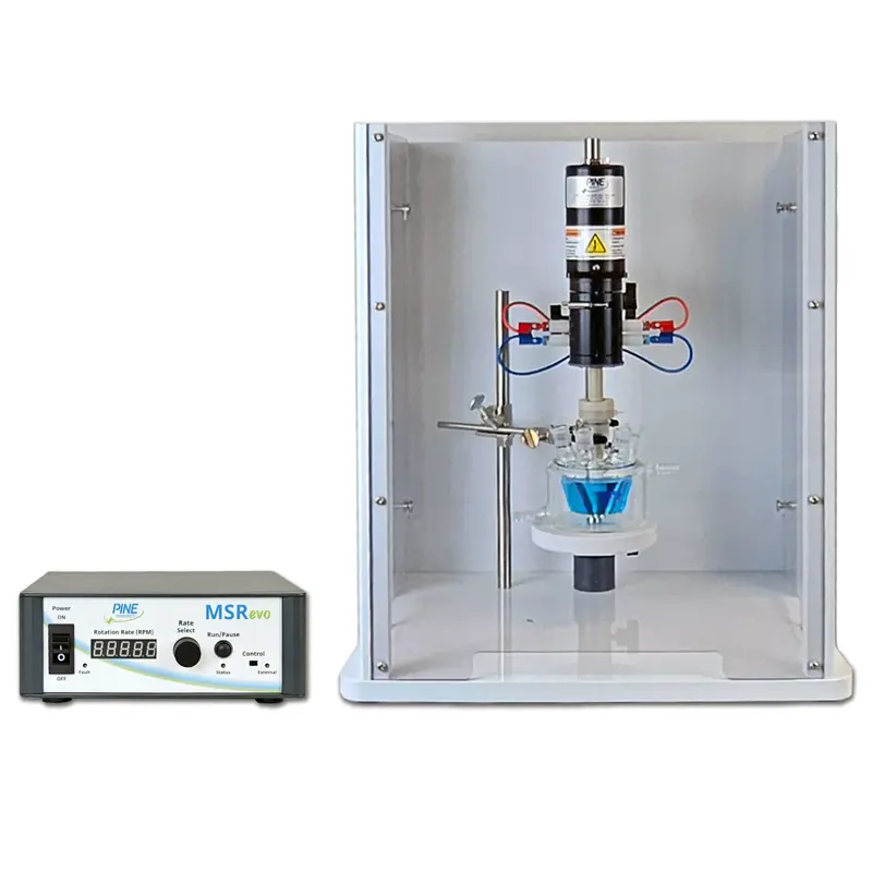
Figure 1: Electrode Rotator Apparatus (Pine Research MSR evo) |
Figure 2: Rotating Ring-Disk Electrode (Glassy Carbon Disk, Platinum Ring, PTFE shroud) |
2. Rotating Electrodes
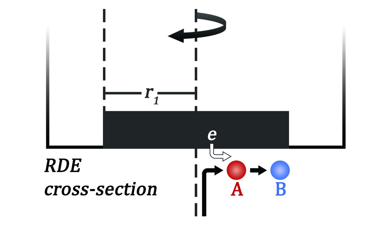
There are two principle rotating electrode geometries which are useful for studying the ORR process. The simplest geometry is the rotating disk electrode consisting of an electrode material (usually glassy carbon) fashioned into a disk shape and shrouded by an inert insulating material (such as PTFE or PEEK). This disk is mounted (coaxially) on a rigid shaft and typically rotated at rates between 200 and 2500 RPM, setting up a solution flow pattern which brings solution to the disk surface(see Figure 3). For ORR studies, glassy carbon is used as the disk material and catalyst support because carbon is electrochemically inert over the range of electrode potentials relevant to ORR study.
|
|
|
Figure 3: RDE Simplified Flow Cross Section (A is reduced to B at disk) |
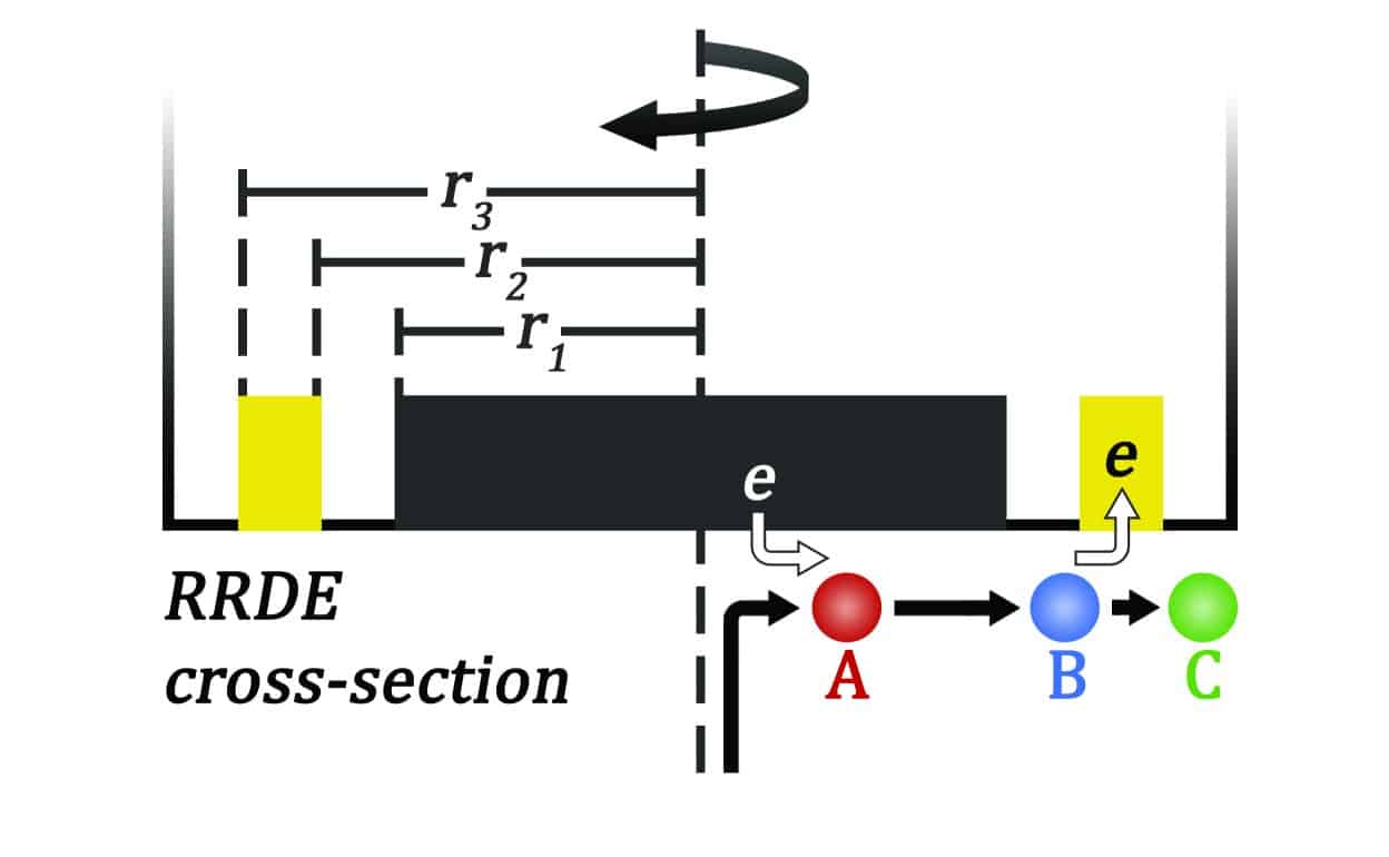
Figure 4: RRDE Simplified Flow Cross Section (A is reduced to B at disk; B is oxidized to C at ring) |
The rotating ring-disk electrode (see Figure 2) is a more complex geometry in which a ring electrode (typically platinum) is placed around the disk electrode with ring, disk, and shaft all sharing the same axis of rotation. When rotating, the solution flow first brings dissolved species into contact with the disk, and then after interacting with the disk, the species travel radially out to the ring (see Figure 4).
In appearance, an RRDE electrode does not look much different than a simple RDE electrode, however, an RRDE may be two to four times more expensive and is a much more delicate research tool. A thin insulating ring forms the gap between the disk and the ring electrode, keeping them electrically isolated, and the outer diameter of the ring is also shrouded by an insulating material. The surfaces of the ring, disk, gap, and shroud are all ideally polished and coplanar. For ORR studies, the ring material is usually platinum to allow for easy detection of any peroxide formed by the catalyst on the disk electrode.
3. Basic Concepts
Using the RDE and RRDE to study ORR electrocatalysts requires understanding of a few basic ideas. For the RDE, the key point is understanding the combined effects of mass transport (i.e., how fast does oxygen travel to the disk electrode?) and fundamental kinetics (i.e., how fast is the oxygen reduced once it reaches the electrode?). For the RRDE, the key point is realizing that the ORR products (hydroxide and peroxide) generated at the disk must subsequently travel past the ring electrode. While the disk produces (generates) the products, the ring detects (collects) the products. This generator-collector geometry allows direct detection of any peroxide formed by the catalyst.
3.1. RDE Kinetic Measurements
A glassy carbon rotating disk electrode coated with a thin layer of an ORR electrocatalyst may be used to reduce dissolved oxygen in an electrolyte solution []. By gradually increasing the rotation rate of the RDE, the rate of mass transport of the dissolved oxygen to the electrode surface increases. Initially, the cathodic (reduction) current at the disk electrode is governed by this mass transport (i.e., the rate at which oxygen is arriving at the electrode). As the rotation rate increases, the current increases as the amount of oxygen arriving at the electrode surface increases.
Eventually, at a high enough rotation rate, the rate at which oxygen arrives at the electrode surface approaches the rate at which the electrocatalyst reduces the oxygen. At this point, the current signal measured at the disk electrode begins to be governed (or more precisely, limited) by the kinetic properties of the catalyst. It is at these higher rotation rates that the measured disk current begins to yield kinetic information. This category of RDE experiment is usually called a Koutecky-Levich experiment, and the reader is referred to textbook explanations [] of this method for further theoretical details.
3.2. RRDE Peroxide Detection
The solution flow pattern induced by a rotating electrode continually mixes the test solution and draws fresh solution toward the disk electrode. The chemical species of interest, dissolved oxygen in this case, is drawn by the flow toward the disk electrode, and upon encountering the catalyst coated electrode surface, it is reduced. The ORR process yields some ratio of hydroxide to peroxide as products, depending on whether the catalyst favors the so-called four electron pathway versus the two electron pathway. The two electron pathway (leading to peroxide) is disadvantageous in a fuel cell context, as peroxide generally goes on to damage other critical materials comprising the fuel cell.
Some of the products generated at the disk electrode will move in an outward (radial) direction via a combination of convection and diffusion. These products can be detected if a suitable ring electrode is placed around the disk electrode. Peroxide is conveniently detected electrochemically using a platinum ring electrode. By comparing the amount of oxygen reduced at the disk (as indicated by the disk current) to the amount of peroxide detected at the ring (as indicated by the ring current), it is possible to deduce the fraction of oxygen which was reduced via the two electron pathway versus the four electron pathway. This use of an RRDE is often called a “collection” experiment, and the reader is again referred to textbook explanations [] and to specific research reports [] for further details.
4. Practical Matters
While textbooks and research reports provide theoretical background for Koutecky-Levich and RRDE Collection experiments, the technical aspects of actually conducting the experiment often go unmentioned. This section contains hints and advice gleaned from several researchers who have used Pine Research electrodes in their ORR research projects.
4.1. Polishing Electrodes
The glassy carbon disk electrode (whether on an RDE or an RRDE) should be clean and mirror polished prior to use. It should also be completely dry. Routine polishing of glassy carbon RDEs is fairly straightforward, but for an RRDE, it is generally best to polish the disk separately from the ring. Attempting to polish the ring and the disk at the same time is likely to cross-contaminate the disk with platinum debris from the ring. This can be a not so obvious source of error in an ORR study as such debris will likely also behave as an ORR catalyst. Many Pine Research RRDE designs permit the disk material to be ejected from the RRDE assembly for separate polishing. The glassy carbon disk insert, once ejected, can be mounted in a separate holder for hand polishing (see Figure 5).
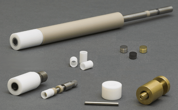
Figure 5: Some RRDE Designs can be Completely Disassembled
(to facilitate polishing, drop coating, and catalyst imaging)
4.2. Coating Catalyst on Disk Electrode
The most popular way to immobilize an ORR electrocatalyst uses Nafion® as the glue which sticks the catalyst particles to the glassy carbon disk. A suspension of catalyst particles and Nafion® is prepared in a suitable solvent, and then a portion of this suspension is drop coated on to the disk. The solvent is allowed to evaporate, leaving behind a thin film of Nafion® with embedded catalyst particles.
The catalyst dispersion is prepared by quantitatively dispersing a known amount of catalyst in a known volume of solvent (500 to 1000 μg of catalyst per milliliter of solvent). In general, this dispersion can be prepared in a common 20 mL disposable vial.
Because the catalyst will not actually dissolve, ultrasonication is required to create a uniform dispersion of catalyst particles in the solvent. When possible, pure water should be used as the solvent, but some hydrophobic catalysts may require the use of 20% to 40% isopropyl alcohol as the solvent. In general, the amount of alcohol should be kept to a minimum as it may frustrate the drop coating procedure (see below).
Nafion® is generally available as a 5% (by mass) solution in alcohols and water. To introduce Nafion® into the catalyst dispersion, use a micropipette to add 200 μL of 5% Nafion® solution for every 50 mL of catalyst dispersion. Additional mixing and sonication is required after adding the Nafion®. The elapsed time between this final ultrasonication step and the subsequent drop coating step should be minimized to avoid undue settling of the dispersion.
The drop coating step is by far the most difficult step. The idea is to use a micropipet to transfer a known volume of the catalyst dispersion on to the disk electrode, and only on to the disk electrode. For a 5.0 mm OD glassy carbon disk electrode, about 20 μL of the dispersion should be placed on to the disk. After evaporation of the solvent, a thin Nafion® film (~0.1 μm thick) should remain on the disk. From the concentration of the catalyst in the dispersion and the known volume dispensed on to the disk electrode, it should be possible to estimate the amount of catalyst in the thin film. Thick films (more than 0.5 μm) should be avoided as these may interfere with ideal solution flow at a rotating electrode.
Drop coating on to an RRDE is a bit more tedious. Here, the close proximity of the ring to the disk can make it difficult to coat just the disk and not the ring. One factor which aids in this regard is the fact that the gap between the disk and the ring is often made from PTFE, which is somewhat hydrophobic. This tends to help confine the drop to the glassy carbon disk as long as the solvent is predominately water. However, when additional alcohol is used to prepare the dispersion, the drop is more prone to wetting the PTFE as well as the glassy carbon disk, and this may frustrate drop coating efforts.
After drop coating, many researchers accelerate the drying process by placing the electrode in an oven. Extreme temperatures should be avoided when heating Pine Research electrodes, and baking a rotating electrode may cause it to leak (i.e., breaking the seal between the disk and the insulating shroud). Another problem with evaporating the solvent in a “bone dry” environment is that concentric rings of catalyst particles may form on the glassy carbon disk (rather than a uniform film). Some researchers have suggested that it is better to dry the film slowly in a somewhat humid environment. This may help alleviate concentric segregation of the catalyst particles in the resulting film.
4.3. Rotation Rates
In Koutecky-Levich experiments, the range of useful rotation rates is typically between 100 and 3000 RPM. Be sure that the RDE being used is rated for this range of rotation rates. For the RRDE Collection experiments, a rotation rate between 1500 and 2000 RPM is generally sufficient. Again, be sure to check the range of allowable rotation rates for the particular RRDE being used.
4.4. Elevated Temperatures
Because ORR research is driven in large part by automotive fuel cell target applications, there is a need to characterize electrocatalyst behavior at elevated temperatures. Unfortunately, most RDE and RRDE designs are not stable at elevated temperatures. Pine Research does offer a PEEK-shrouded RDE design which is stable at higher temperatures (see Figure 6). Many researchers use this electrode at a series of elevated temperatures (from 50 to 80ºC) in a set of related Koutecky-Levich experiments. After extracting the kinetic rate constants at each temperature, an Arhennius extrapolation is used to predict the kinetic behavior at still higher temperatures.
In the past, many researchers [] have reported using PTFE-shrouded Pine Research RRDEs at temperatures up to 80ºC in an effort to determine the amount of peroxide formation at higher temperatures. PTFE-shrouded RRDEs are easily damaged by such exposure to high temperatures. Sometimes this damage (usually a leak) can be repaired by replacing the PTFE spacer between the disk and the ring electrode. This piece is called the PTFE U-Cup, and while the U-Cup is itself fairly expensive, it is still much less expensive than replacing the entire RRDE assembly.
Pine Research also offers PEEK-shrouded RRDE designs which may prove more suitable for such higher temperature studies (see Figure 6).
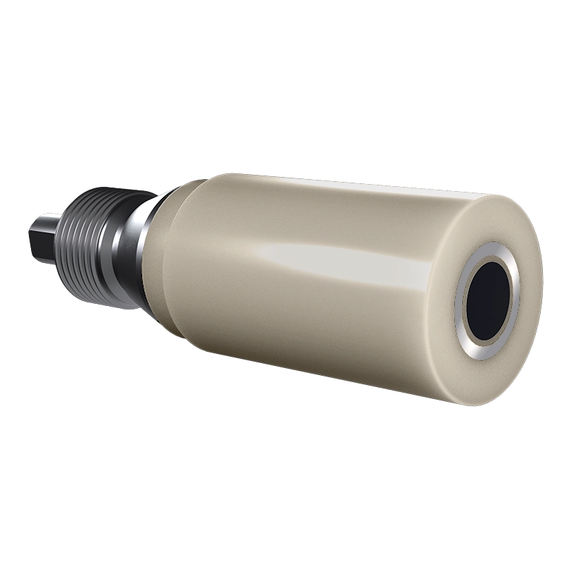
Figure 6: RRDE Tip with PEEK Shroud and PEEK U-Cup
(E6R2 Series RRDE featuring all PEEK design for use up to to 80ºC)
4.5. Collection Efficiency
In an RRDE Collection experiment, not all the product generated at the disk electrode will make the trip to the ring electrode. The flow pattern at a rotating electrode generally sweeps anywhere from 20% to 30% of the disk products past the ring electrode. The percentage of material which is collected (detected) at the ring electrode is often called the collection efficiency of the RRDE.
While theoretical equations for computing the collection efficiency are available, it is always best to empirically measure the collection efficiency of a specific RRDE before using it for any quantitative work. This is normally done using a well-behaved electrochemical system such as the ruthenium hexaamine redox couple. This system can be used to measure a stable collection efficiency at rates between 200 and 2500 RPM. The reader is referred to the appropriate reference [] for more details.
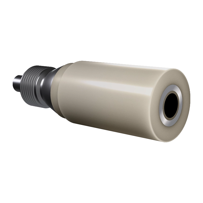
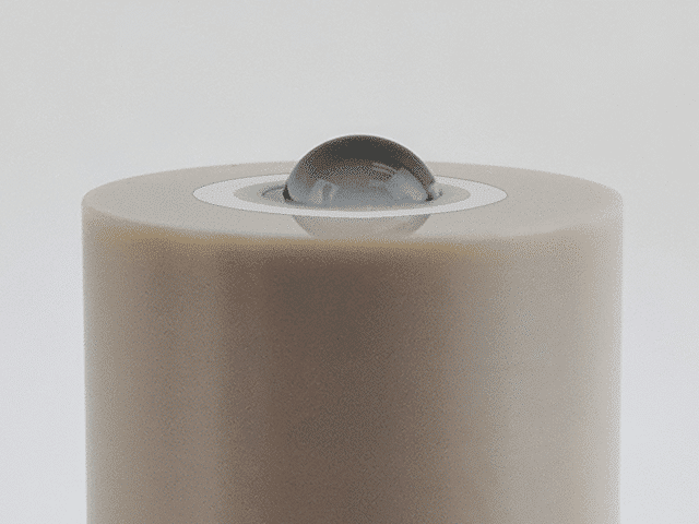
Pine Research offers a series of RRDE tips which have electrode dimensions optimized for a very high collection efficiency (43.9%). These E8R4 Series RRDE tips (see Figure 7) have a PEEK shroud and a PTFE U-Cup. The PTFE U-Cup faciliates drop-coating aqueous solutions on to the disk (see Figure 8). Because the PTFE is slightly hydrophobic, the droplet tends to remain on the disk without spilling over on to the ring.
 |
|
|
Figure 7: High Efficiency E8R4 Series RRDE (collection efficiency greater than 40%) |
Figure 8: Hydrophobic PTFE U-Cup (stabilizes the droplet on disk) |
6. Trademarks
Nafion® is a registered trademark of The Chemours Company FC, LLC.