mobile-main-menu-button
Menu

Category Archives: Uncategorized

  • Windows

    Background: Microsoft Windows Information

    When you are controlling and acquiring data from a scientific instrument with a personal computer, you often must become aquainted with parts of the Microsoft Windows operation system that the average user never encounters. Troubleshooting the physical/electrical connection between the instrument and your personal computer often requires you to view and modify the hardware configuration on your computer.

    In recent years, this process has been made much simpler by the advent of the Universal Serial Bus (USB) ports which are now widely available on most personal computers. Most newer scientific instruments provide a USB port, so that connecting the instrument to the computer is a simple matter of using a standard USB cable. But, many older instruments still require an interface board to be installed inside your computer or make use of the older style RS-232 serial communications port or IEEE 488 parallel port technology.

    Regardless of whether your instrument uses USB, RS-232, IEEE, or some other type of interface board, there will be times that you need to view and configure your computer's ports or board configuration. Windows stores information about hardware boards and ports in the system Registry, which is a large database containing all the information about your personal computer. Directly editing the contents of the Registry is generally not a good idea, so Microsoft has provided two different utilities for viewing and changing the hardware configuratin on your computer. These utilities are called the Device Manager and the Control Panel.

    The Device Manager

    The Device Manager allows you to directly view a long list of the various hardware components connected to your system. This list includes the usual components that you would expect to see, such as the system's disk drives, keyboard, mouse, video, sound and networking components. But, the list also includes any data acquisition boards or ports (USB, RS-232, or IEEE) being used by a scientific instrument connected to your computer.

    The Device Manager is the “lowest common denominator” when it comes to viewing the devices installed on your system. It provides you with a low level view of all devices, the resources used by these devices, and the special software components (called device drivers) which interact with each hardware device.

    The Control Panel

    The Control Panel is a collection of smaller utility programs (sometimes called “applets”) which give you more specific control over various aspects of your computer's configuration and behavior.

    Read More
  • Working Electrode

    Electrochemical cells have at least two electrodes, and those cells used for analysis purposes usually have three electrodes. While various redox reactions occur at each of these electrodes, there is usually one particular electrode in the cell which is the focus of the experiment or analysis in question. This principle electrode is called the working electrode.

    In a typical three electrode voltammetry experiment, there is a working electrode, a reference electrode, and a counter electrode. A redox process of interest is studied at the working electrode by controlling the potential of the working electrode with respect to the reference electrode while measuring the current at the working electrode.

    Some electroanalytical cells have more than just one working electrode. A very common example is in rotating ring-disk voltammetry, where both the ring electrode and the disk electrode are considered to be working electrodes.


    Related Terms: counter electrode, reference electrode, three electrode cell

    Read More
  • Rotating Ring-Disk Electrode (RRDE)

    Overview

    A Rotating Ring-Disk Electrode (RRDE) is a special type of working electrode used for analytical purposes in an electrochemical cell. Spinning a disk at high speed in an electrolyte solution sets up a well-defined mass transport flow condition. Material is initially transported by the solution flow to the disk electrode and then subsequently past the ring electrode.

    Collection Efficiency

    The theoretical collection efficiency can be computed from the three principle diameters describing the RRDE geometry: the disk outer diameter ( d_1 ), the ring inner diameter ( d_2 ), and the ring outer diameter ( d_3 ). This somewhat tedious computation is made easier by normalizing the ring diameters with respect to the disk diameter

    {\sigma}_{OD} = \frac{d_3}{d_1}

    {\sigma}_{ID} = \frac{d_2}{d_1}

    and by defining three additional quantities in terms of the normalized diameters

    {\sigma}_{A} = {\sigma}_{ID}^3 - 1

    {\sigma}_{B} = {\sigma}_{OD}^3 - {\sigma}_{ID}^3

    {\sigma}_{C} = \frac{{\sigma}_{A}}{{\sigma}_{B}}

    and by defining a complex function,  G(x) , as follows:

    G(x) = \frac{1}{4} + \left(\frac{\sqrt{3}}{4{\pi}}\right) ln \left[{\frac{(x^{1/3} + 1)^3}{x+1}}\right] + \frac{3}{2{\pi}} {\arctan}\left[{\frac{2x^{1/3}-1}{\sqrt{3}}}\right]

    In terms of the normalized quantities and complex function above, the theoretical collection efficiency ( N_{theoretical} ) for a rotating ring disk electrode is given by the following equation:

    N_{theoretical} = 1-{\sigma}_{OD}^2+{\sigma}_B^{2/3}-G({\sigma}_C)-{\sigma}_B^{2/3}G({\sigma}_A)+{{\sigma}_{OD}^2}G({\sigma}_C{\sigma}_{OD}^3)

    References

    Allen J. Bard and Larry R. Faulkner, Electrochemical Methods: Fundamentals and Applications, New York: Wiley, 2001, 2nd ed., Chapter 9.

    Read More
  • Quiescent Solution

    A quiescent solution is a liquid solution that is unstirred.

    Read More
  • Reduction

    In the field of chemistry, the term reduction is used to describe a process involving a gain of electrons by an atom, ion, or molecule. In a chemical reaction where one reactant is reduced (i.e., gain of electrons), one or more of the other reactants undergo oxidation (i.e., loss of electrons).

    An example of a chemical reaction involving oxidation and reduction is the reaction of hydrogen with chlorine (shown below).

    H_2 + Cl_2 \rightarrow 2HCl

    The two reactants on the left side of the chemical equation are both elements with an oxidation number equal to zero. But when these elements react to form the product,  HCl , the hydrogen has a higher oxidation number (+1) and the chlorine has a lower oxidation number (-1). In this reaction, the hydrogen has undergone oxidation while the chlorine has undergone reduction.

    When writing down an electrochemical half reaction, it is generally quite clear when the half reaction is written as a reduction half reaction. If the electrons appear as reactants (rather than as products) in the half reaction, then the half reaction has been written as an reduction process (see example below).

    Fe^{3+} + e^- \rightarrow Fe^{2+}

    In the example above, the iron(III) cation gains an electron to become iron(II); thus, the iron(III) cation is reduced.


    Related Terms: redox, half reaction, cathode, cathodic current

    Antonyms: oxidation

    Read More
  • Half Reaction


    By convention, redox half reactions are generally tabulated in textbooks and other reference works as reduction reactions with the oxidized form on the left side and the reduced form on the right side, but it is understood that the reaction may occur in either direction.

    Standard Electrode Potential

    Given that electrochemical half reactions can occur in either direction, they are often written using chemical equilibrium notation* as follows:

    O + ne^- \rightleftharpoons R

    Each half reaction has an associated standard electrode potential ( E^{{\circ}} ) which is a thermodynamic quantity related to the free energy associated with the equilibrium. Like many other standard thermodynamic quantities, the standard electrode potential corresponds to a given standard state. The standard state corresponds to a thermodynamic system where the chemical activities of O and R are unity (i.e., when all solution concentrations are  \text{1.0 mol/L} , all gases are present at  \text{1.0 bar} partial pressure, and other materials are present as pure phases with unity activity).

    Nernst Equation

    To account for the very likely possibility of non-unity activities, the Nernst equation (see below) can be used to express the equilibrium electrode potential ( E_{NERNSTIAN} ) in terms of the actual activities ( a_O and  a_R )

    E_{NERNSTIAN} = E^{\circ} + \left(\frac{RT}{nF}\right)ln\left[{\frac{a_O}{a_R}}\right]

    where  F is the Faraday constant ( \text{F = 96485 C/mol} ),  R is the ideal gas constant ( \text{R = 8.3145 J} \; mol^{-1} \; K^{-1} ), and  T is the absolute temperature ( K) . Usually, the activities of molecules or ions dissolved in solution are assumed to be the same as their molar concentrations.

    Additional Links

    Read More
  • Oxidation

    In the field of chemistry, the term oxidation is used to describe a process involving a loss of electrons by an atom, ion, or molecule. In a chemical reaction where one reactant is oxidized (i.e., loss of electrons), one or more of the other reactants undergo reduction (i.e., gaining electrons).

    An example of a chemical reaction involving oxidation and reduction is the reaction of hydrogen with chlorine (shown below).

    H_2 + Cl_2 \rightarrow 2HCl

    The two reactants on the left side of the chemical equation are both elements with an oxidation number equal to zero. But when these elements react to form the product,  HCl , the hydrogen has a higher oxidation number ( +1 ) and the chlorine has a lower oxidation number ( -1 ). In this reaction, the hydrogen has undergone oxidation while the chlorine has undergone reduction.

    When writing down an electrochemical half reaction, it is generally quite clear when the half reaction is written as an oxidation half reaction. If the electrons appear as products (rather than reactants) in the half reaction, then the half reaction has been written as an oxidation process (see example below).

    Fe^{2+} \rightarrow Fe^{3+} + e^-

    In the example above, the iron(II) cation loses an electron to become iron(III); thus, the iron(II) cation is oxidized.


    Related Terms: redox, half reaction, anode, anodic current

    Antonyms: reduction

    Read More
  • Faradaic Current

    The current observed at a working electrode in an electrochemical experiment is often the sum of the current due to redox reactions occurring at the electrode surface and other currents such as capacitive charging/discharging of the electrode double layer.

    The portion of the current usually of interest to an electrochemist is the current caused by the redox reaction(s) at the electrode surface. This portion of the current is called the Faradaic current.


    Related Terms: anodic current, cathodic current

    Antonyms: non-Faradaic current

    Read More
  • Glossary

    The glossary contains a list of terms commonly used in the electrochemical sciences. If you wish to make changes or additions to this glossary, then be sure to click here to read the instructions.

    Read More
  • Connector Colors

    There is no industry-wide standard for assigning colors to the various electrode connections on a potentiostat. Each manufacturer has settled on a different color coding, and some manufacturers, including Pine, have changed color coding schemes over the years. This article attempts to address this confusing subject and bring together what is presently known about potentiostat color codes.

    Pine Research Instrumentation (Raleigh, NC) is a spin-off company of Pine Instrument Company (Grove City, PA). These two related companies have used two different color coding standards, both of which are described below. Since 2007, Pine Research Instrumentation has used the “PRI Standard” described below for potentiostats and rotators. Before 2007, an older “PIC Standard” was used, and this too, is described below.

    The "PRI Standard" Color Scheme (after 2007)

    Pine potentiostats and rotators designed after the year 2007 utilize the following color scheme.

    standard_color_code.jpg

    Product examples which use this color scheme include the universal cell cable for the WaveNow USB Potentiostat and the generic cell cable sold with Pine's Student Voltammetry Cell.

    The "PIC Standard" Color Scheme (before 2007)

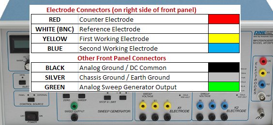
    The older model analog bipotentiostats offered by Pine Instrument Company (part numbers AFRDE3, AFRDE4, AFRDE5, and AFCBP1) used the following color scheme. Note that on the AFCBP1 the electrode connections are located along the right side of the front panel. On the earlier models (AFRDE3, AFRDE4, and AFRDE5), the electrode connections were located along the bottom-left of the front panel.

    afcbp1colorcode.jpg

    All of the traditional analog bipotentiostats offered by Pine Instrument Company featured a built-in, true analog sweep generator. Additional output signals on the front panels of these instruments permitted the sweep generator and/or the current and voltage signals from either electrode to be used to drive a classic XY pen plotter. These connections appear along the bottom of the front panel of these instruments.

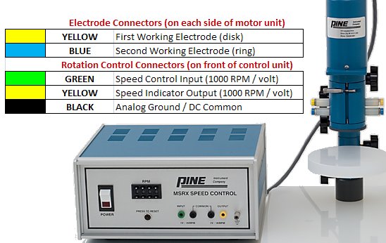
    The older model MSR rotators (part numbers AFMSRX and AFMSRXE) used the following color scheme.
    msr_color_scheme_old.jpg
    Read More