mobile-main-menu-button
Menu

Category Archives: Uncategorized

  • Does Sales or Use tax apply to my purchase?

    When purchasing products on the Pine Research Instrumentation website, please note the following:

    1. Sales or use tax may be due on certain purchases delivered or sourced to your state. Your state may require you to file a use tax return when sales tax is not paid at the time of purchase.
    2. Pine Research is not required to, and does not, collect sales or use tax for your state. Under some state laws, purchases are not tax-exempt merely because a seller is not required to collect sales tax. Purchasers should review untaxed purchases and, if any tax is owed, file a use tax return and pay any tax due. Contact the Department of Revenue for your state for more information.
    Read More
  • MSR Rotator: Parts and Accessories

    7.1 Mechanical Parts and Hardware

    From brush replacement kits to cell platforms and everything in between, many of the spare parts for the MSR Rotator are conveniently located on the same page. All of these parts are subject to normal wear during routine use.

    Other normal wear may occur during routine use on the following moving parts (product pages can be accessed by clicking the text):

    7.2 Power Cords

    Figure-6.1-C18-Plug.jpg   Figure-7.1-Power-Entry-Module.jpg

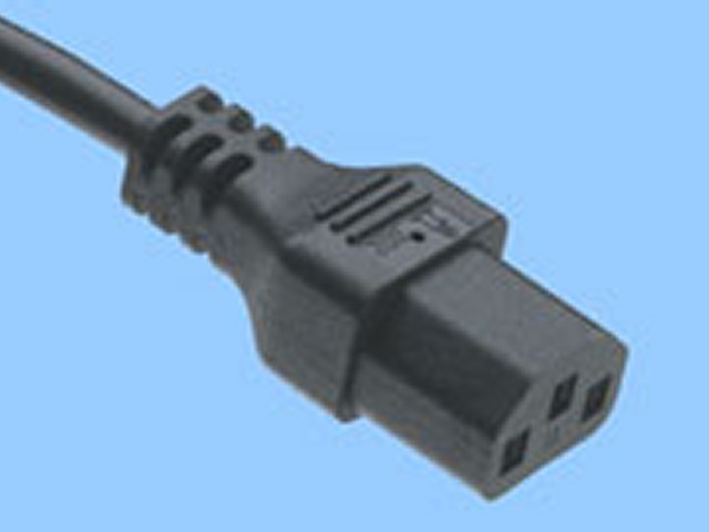
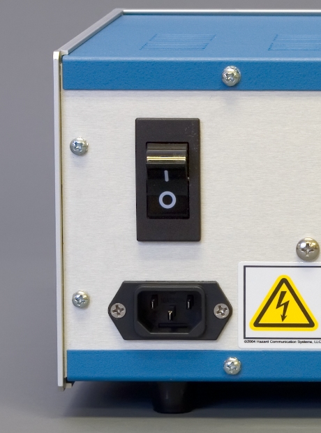
    Figure 7.1: Standard C-18 Connection on Power Entry Module

    The power entry module on the back panel of the control unit accepts any power cord compatible with a standard C18 plug (see: Figure 7.1). A wide range of power cord options can be accessed via the button below.

    7.3 Power Supplies

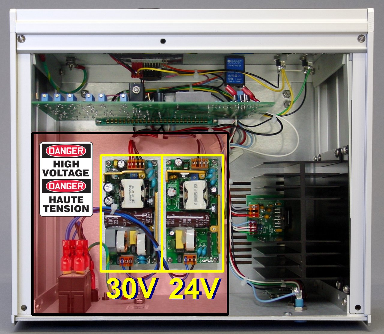
    The rotator control unit has two internal power supplies. One of these power supplies is  \text{30 VDC (100 W)} and the other is  \text{24 VDC (65 W)} . These power supplies are located within the high voltage section of the control unit (see: Figure 7.2).

    Figure-7-2-MSR-power-supplies.jpg

    Figure 7.2: Location of High Voltage Power Entry and Internal Power Supplies


    electric_shock.jpg

    WARNING:

    Risk of electric shock.
    Disconnect power before servicing the control unit.
    The shaded region in Figure 7.2 (above) shows the location of the high voltage power entry and the two internal power supplies.

    AVERTISSEMENT:

    Risque de décharge électrique.
    Déconnectez l’alimentation avant de procéder à l’entretien de l’unité de commande.
    La région ombragée de la figure 7.2 (ci-dessus) présente l’emplacement de l’entrée de puissance à haute tension et des deux alimentations internes.

    In the (rare) event that it is necessary to replace one of the internal power supply units, it is important to carefully identify which type of power supply is to be replaced. First, determine which supply ( \text{30 V} or  \text{24 V} ) is to be replaced (see: Figure 7.2).

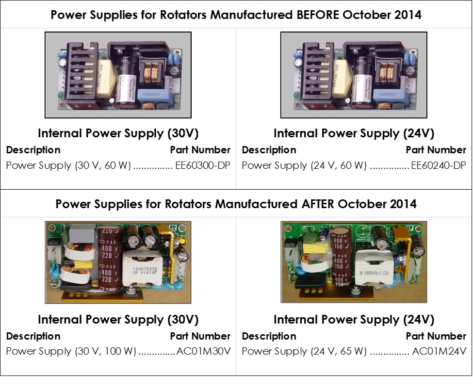
    Next, carefully examine the power supply to determine which brand of power supply is to be replaced. Early rotators (prior to October 2014) use power supplies manufactured by Astrodyne, FranMar International or TDK Lambda. Later rotators (after October 2014) use power supplies manufactured by XP Power. Depending upon when the rotator was manufactured, choose the appropriate replacement part shown below.

    Figure7_3Website.jpg

    Figure 7.3: Replacement Internal Power Supplies


    electric_shock.jpg

    WARNING:

    Risk of electric shock.
    Disconnect all power before servicing the rotator.

    AVERTISSEMENT:

    Risque de décharge électrique.
    Déconnectez toutes les sources d’alimentation avant de procéder à l’entretien du rotateur.


    rotating-hazard.jpg

    WARNING:

    Rotating shaft. Entanglement hazard.
    Turn off the power to the rotator and disconnect the power cord from the power source before continuing with this procedure.

    AVERTISSEMENT:

    Arbre en rotation. Danger d’enchevêtrement.
    Éteignez le rotateur et débranchez le cordon d’alimentation de la source d’alimentation avant de poursuivre cette procédure.

    Read More
  • Electrodes

    Table of Contents

    • Section 5: Electrodes
      • 5.1 Electrode Handling Precautions
      • 5.2 Shafts
      • 5.3 RDE Tips
      • 5.4 Single-Piece RDE Designs
      • 5.5 RRDE Tips
      • 5.6 RCE Tips

    5.1 Precautions

    Rotating electrode tips and shafts are precision research tools machined to tight specifications for proper balance when spinning at high rotation rates. When not in use, an electrode tip should be cleaned, dried, and stored in its original case. When working with electrode shafts and tips, special care should be taken not to drop the shaft or tip as this will likely throw the shaft or tip off balance.

    icon_caution.jpg

    WARNING:

    Do not use or attempt to rotate an electrode shaft that has been dropped, bent or otherwise physically damaged.
    Inspect the shaft to be certain that it is not damaged.

    AVERTISSEMENT:

    N’utilisez pas et ne tentez pas de mettre en rotation un arbre d’électrode qui est tombé, a été tordu ou a été endommagé physiquement d’une autre manière ou d’une autre.
    Inspectez l’arbre pour vous assurer qu’il n’a pas été endommagé.


    icon_caution.jpg

    WARNING:

    Do not use or attempt to rotate an electrode tip that has been dropped or otherwise physically damaged.
    Inspect the electrode tip to be certain that it is not damaged.

    AVERTISSEMENT:

    N’utilisez pas et ne tentez pas de mettre en rotation un embout d’électrode qui est tombée ou a été endommagée physiquement d’une autre manière ou d’une autre.
    Inspectez l’embout d’électrode pour vous assurer qu’elle n’a pas été endommagée.


    icon_caution.jpg

    WARNING:

    Do not use an electrode shaft which appears to wobble, vibrate, or tilt away from the axis of rotation while rotating. Such a shaft is either improperly installed or physically damaged. Turn off the rotator, disconnect electrical power, and remove the shaft immediately.

    AVERTISSEMENT:

    N’utilisez pas un arbre d’électrode qui semble osciller, vibrer ou dévier de l’axe de rotation pendant la rotation. Cet arbre est soit installé de manière incorrecte soit endommagé physiquement. Éteignez le rotateur, déconnectez l’alimentation électrique et retirez l’arbre immédiatement.


    icon_caution.jpg

    WARNING:

    Do not use an electrode tip which appears to wobble, vibrate, or tilt away from the axis of rotation while rotating. Such an electrode tip is either improperly installed or physically damaged. Turn off the rotator, disconnect electrical power, and remove the electrode tip immediately.

    AVERTISSEMENT:

    N’utilisez pas un embout d’électrode qui semble osciller, vibrer ou dévier de l’axe de rotation pendant la rotation. Cet embout d’électrode est soit installée de manière incorrecte soit endommagée physiquement. Éteignez le rotateur, déconnectez l’alimentation électrique et retirez l’embout d’électrode immédiatement.


    icon_caution.jpg

    CAUTION:

    Do not exceed the maximum rotation rate for an electrode.
    Each type of rotating electrode has a specific maximum rotation rate limitation. Consult the documentation for the specific electrode being used in order to learn the maximum rotation rate for that electrode.

    ATTENTION:

    Ne dépassez pas la vitesse de rotation maximum pour une électrode.
    Chaque type d’électrode rotative possède une vitesse de rotation maximum spécifique.
    Consultez la documentation pour l’électrode spécifique à utiliser pour connaître la vitesse de rotation maximum de l’électrode.


    icon_caution.jpg

    CAUTION:

    Do not apply excessive twisting force to the shroud of an electrode tip when threading it on to the shaft, as this may cause a leak between the shroud and the electrode.

    ATTENTION:

    N’appliquez pas une force de torsion excessive à l’enveloppe de protection d’un embout d’électrode lorsque vous la vissez sur l’arbre, car cela pourrait provoquer une fuite entre l’enveloppe de protection et l’électrode.


    icon_caution.jpg

    CAUTION:

    Position the motor unit with respect to the glass cell so that the electrode tip is immersed approximately  \textbf{1.0 cm} into the test solution.
    Excessive immersion may corrode the shaft or tip by allowing liquids to seep into the joint between the shaft and tip.

    ATTENTION:

    Positionnez le bloc moteur en fonction de la position de la cellule de verre, de telle sorte que l’embout d’électrode soit immergée sur environ 1 cm dans la solution d’essai.
    Une immersion excessive peut entraîner la corrosion de l’arbre ou d’embout d’électrode en provoquant l’infiltration de liquides dans le joint situé entre l’arbre et l’embout d’électrode.


    icon_caution.jpg

    CAUTION:

    Center the rotating electrode within the opening on the cell so that it does not rub against the walls of the opening.
    Damage will occur if the rotating shaft or tip abrades against these walls.

    ATTENTION:

    Centrez l’électrode rotative dans l’ouverture de la cellule pour qu’elle ne frotte pas les bords de l’ouverture.
    Le frottement des bords de la cellule par l’arbre ou par l’embout d’électrode entraînera des dommages.


    icon_heat.jpgTEMPERATURE LIMITATIONS:

    Electrode tips with PTFE shrouds are designed for use at room temperature (\textbf{15}\boldsymbol{^\circ} \textbf{C} to \textbf{30}\boldsymbol{^\circ} \textbf{C}). Exposing these tips to colder or warmer temperatures is likely to compromise the seal between the PTFE shroud and the electrode surface.
    Electrode tips with PEEK or PCTFE shrouds are available and are better suited for use at elevated temperatures.

    icon_info.jpgNOTE:

    After each use of rotating electrode (or electrode tip), clean and dry the electrode and then return it to the plastic storage box in which it was originally shipped.

    icon_info.jpgNOTE:

    A polishing kit is available for use in restoring the electrode surface to its original mirror smooth finish. A slurry of microscopic abrasive particles may be used to routinely repolish the electrode surface (usually at the end of each day). In the event of very serious damage to the electrode surface, it is generally better to return the electrode to the factory for professional repolishing.

    5.2 Shafts

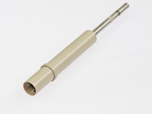
    The rotator accepts a variety of different shaft designs (each sold separately) having a sturdy metal internal shank that is insulated with a polymeric shroud. The upper portion of the shaft is designed to mate with the motor coupling inside the brush chamber (see Figure 4.2). The lower portion of the shaft is protected with a chemically resistant shroud material (PTFE, PEEK, or PCTFE).

    Standard Shafts

    Standard RDE & RCE Shaft (12 mm OD)

    MSR-Shaft-AFE3M.jpg

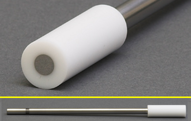
    The Standard RDE & RCE Shaft (12 mm OD) has a PTFE shroud and is compatible with E3 and E4TQ Series RDE tips as well as classic 12 mm OD RCE tips. Further information and purchase details are available.

    Precision Shafts

    Precision RDE & RRDE Shaft (15 mm OD)

    MSR-Shaft-AFE6MB.jpg

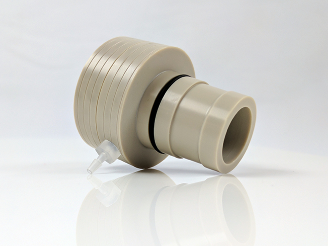
    The Precision RDE & RRDE Shaft (15 mm OD) is specifically designed to mate with the gas purged bearing assembly. The shaft is compatible with E5, E5TQ, E5HT, E6, E6R2, & E7 Series Tips. Further information and purchase details are available.

    Precision RCE Shaft (15 mm OD)

    MSR-Shaft-AFE9MBA.jpg

    The Precision RCE Shaft (15 mm OD) is specifically designed to mate with the gas purged bearing assembly and accepts cylinder inserts. Further information and purchase details are available.

    Bearing Assemblies

    Gas-Purged Bearing Assembly (15 mm ID)

    Bearing-Assembly-15-mm-ID-gas-purged-AC01TPA6M.jpg   Bearing-Assembly-15-mm-ID-gas-purged-example-use.jpg

    The Gas-Purged Bearing Assembly is precision-machined to enable the air-free performance of RDE, RCE, and RRDE experiments that utilize a precision 15 mm OD shaft. Further information and purchase details are available.

    Simple Taper Plug Assembly (6.35 mm ID)

    Bearing-Assembly-12-mm-ID-AC01TPA.jpg

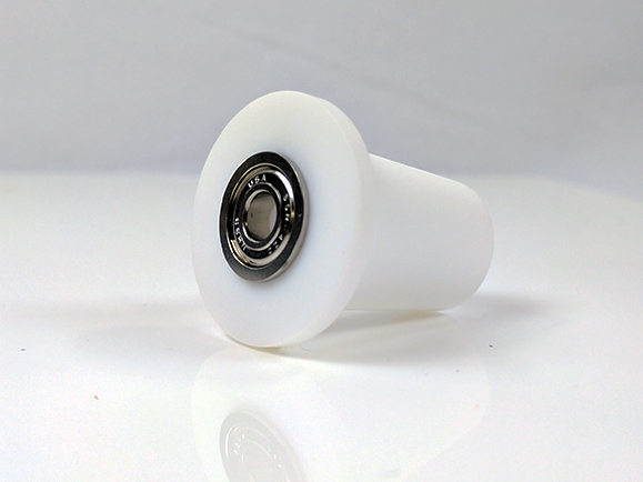
    The Simple Taper Plug Assembly enables users working with a Standard RCE or RDE shaft to perform air-free experiments. Further information and purchase details are available.

    5.3 RDE Tips

    The rotator is compatible with a variety of RDE tips (sold separately), and each tip design is compatible with one or more shafts as described below.

    E3 Series

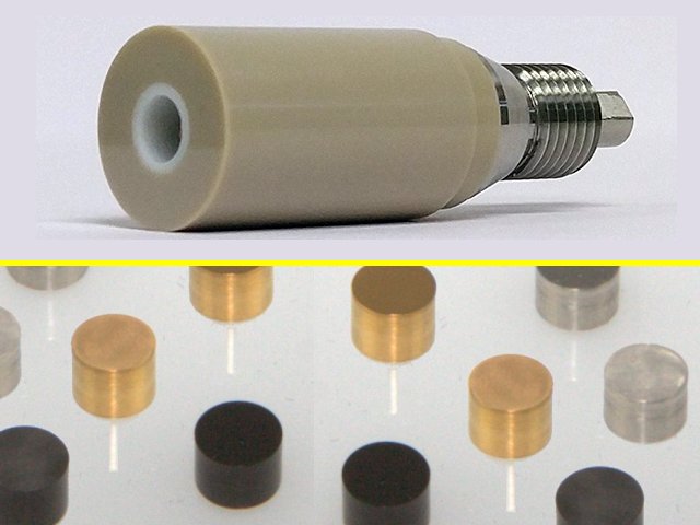
    E3TPK Series RDE Tips (PEEK shroud)

    E3TPK-Series.png

    icon_caution.jpg

    CAUTION:

    Maximum Rotation Rate:  \textbf{2500 RPM} Do not rotate at rates higher than the maximum rotation rate.

    ATTENTION:

    Vitesse de rotation maximum:  \textbf{2500 TR/MIN} Ne mettez pas l’appareil en rotation à des vitesses supérieures à la vitesse de rotation maximum.


    icon_heat.jpgTEMPERATURE LIMITATIONS:

    OPERATING TEMPERATURE RANGE: \textbf{10}\boldsymbol{^\circ} \textbf{C} to \textbf{80}\boldsymbol{^\circ} \textbf{C}.

    Do not use this electrode outside the operating temperature range.

    icon_corrosive.jpg

    CHEMICAL INCOMPATIBILITY:

    Shrouds fabricated from PEEK may be discolored by prolonged exposure to concentrated acids.

    The E3TPK Series RDE Tips (12 mm OD PEEK shroud) fit the standard RDE shaft and their 5 mm disks can be constructed with many different materials. Further information and purchase details are available.

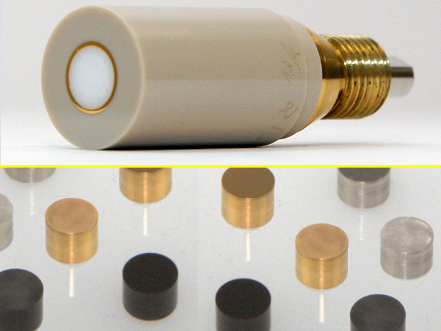
    E3T Series RDE Tips (PTFE shroud)

    RDE-Tip-E3-Series.jpg

    icon_caution.jpg

    CAUTION:

    Maximum Rotation Rate:  \textbf{2500 RPM} Do not rotate at rates higher than the maximum rotation rate.

    ATTENTION:

    Vitesse de rotation maximum:  \textbf{2500 TR/MIN} Ne mettez pas l’appareil en rotation à des vitesses supérieures à la vitesse de rotation maximum.


    icon_heat.jpgTEMPERATURE LIMITATIONS:

    OPERATING TEMPERATURE RANGE: \textbf{15}\boldsymbol{^\circ} \textbf{C} to \textbf{25}\boldsymbol{^\circ} \textbf{C} Do not use this electrode outside the operating temperature range.

    The E3T Series RDE Tips (12 mm OD PTFE shroud) fit the standard RDE shaft and their 5 mm disks can be constructed with many different materials. Further information and purchase details are available.

    E4 ChangeDisk Series

    E4TQ Series ChangeDisk RDE Tips

    AFE4TQ050_with_disks.jpg

    icon_caution.jpg

    CAUTION:

    Maximum Rotation Rate:  \textbf{2000 RPM} Do not rotate at rates higher than the maximum rotation rate.

    ATTENTION:

    Vitesse de rotation maximum:  \textbf{2000 TR/MIN} Ne mettez pas l’appareil en rotation à des vitesses supérieures à la vitesse de rotation maximum.


    icon_heat.jpgTEMPERATURE LIMITATIONS:

    OPERATING TEMPERATURE RANGE: \textbf{15}\boldsymbol{^\circ} \textbf{C} to \textbf{25}\boldsymbol{^\circ} \textbf{C} Do not use this electrode outside the operating temperature range.

    The E4TQ Series ChangeDisk RDE Tips (12 mm OD PTFE shroud) accept a removable disk insert; Pine Research offers a variety of disk insert materials. These tips fit the standard RDE shaft. Further information and purchase details are available.

    E5 Series

    E5TPK Series RDE Tips (PEEK shroud)

    E5TPK-side-view.png

    icon_caution.jpg

    CAUTION:

    Maximum Rotation Rate:  \textbf{3000 RPM} Do not rotate at rates higher than the maximum rotation rate.

    ATTENTION:

    Vitesse de rotation maximum:  \textbf{3000 TR/MIN} Ne mettez pas l’appareil en rotation à des vitesses supérieures à la vitesse de rotation maximum.


    icon_heat.jpgTEMPERATURE LIMITATIONS:

    OPERATING TEMPERATURE RANGE: \textbf{10}\boldsymbol{^\circ} \textbf{C} to \textbf{80}\boldsymbol{^\circ} \textbf{C}.

    Do not use this electrode outside the operating temperature range.

    icon_corrosive.jpg

    CHEMICAL INCOMPATIBILITY:

    Shrouds fabricated from PEEK may be discolored by prolonged exposure to concentrated acids.

    The E5TPK Series RDE Tips (15 mm OD PEEK shroud) fit the standard RRDE shaft. The electrode disk is 5 mm OD and can be constructed from a variety of materials. Further information and purchase details are available.

    E5T Series RDE Tips (PTFE shroud)

    RDE-Tip-E5-Series.jpg

    icon_caution.jpg

    CAUTION:

    Maximum Rotation Rate:  \textbf{3000 RPM} Do not rotate at rates higher than the maximum rotation rate.

    ATTENTION:

    Vitesse de rotation maximum:  \textbf{3000 TR/MIN} Ne mettez pas l’appareil en rotation à des vitesses supérieures à la vitesse de rotation maximum.


    icon_heat.jpgTEMPERATURE LIMITATIONS:

    OPERATING TEMPERATURE RANGE: \textbf{15}\boldsymbol{^\circ} \textbf{C} to \textbf{25}\boldsymbol{^\circ} \textbf{C} Do not use this electrode outside the operating temperature range.

    The E5T Series RDE Tips (15 mm OD PTFE shroud) fit the standard RRDE shaft. The electrode disk is 5 mm OD and can be constructed from a variety of materials. Further information and purchase details are available.

    E5/E6 Series ChangeDisk

    E5TQ Series ChangeDisk RDE Tips (PTFE or PEEK shroud)

    AFE5TQ050PK_with_disks.jpg

    icon_caution.jpg

    CAUTION:

    Maximum Rotation Rate:  \textbf{2000 RPM} Do not rotate at rates higher than the maximum rotation rate.

    ATTENTION:

    Vitesse de rotation maximum:  \textbf{2000 TR/MIN} Ne mettez pas l’appareil en rotation à des vitesses supérieures à la vitesse de rotation maximum.

    icon_corrosive.jpg

    CHEMICAL INCOMPATIBILITY:

    Shrouds fabricated from PEEK may be discolored by prolonged exposure to concentrated acids.

    The E5TQ Series ChangeDisk RDE Tips (15 mm OD shroud composed of PTFE or PEEK) fit the standard RRDE shaft. The electrode disk is 5 mm OD and can be constructed from a variety of materials. A thin, hydrophobic PTFE seal (known as a “U-cup”) surrounds the disk insert when it is mounted in the shroud. Further information and purchase details are available.

    5.4 Single-Piece RDE Designs

    E2MPK Series FastSpeed RDEs (PEEK shroud)

    Pt_GC_AU_001.jpg

    icon_caution.jpg

    CAUTION:

    Maximum Rotation Rate:  \textbf{7000 RPM} Do not rotate at rates higher than the maximum rotation rate.

    ATTENTION:

    Vitesse de rotation maximum:  \textbf{7000 TR/MIN} Ne mettez pas l’appareil en rotation à des vitesses supérieures à la vitesse de rotation maximum.


    icon_no_power.jpg WARNING:

    Rotating shaft. Use extreme caution when operating the rotator at rotation rates above  \textbf{2000 RPM} . Always secure the enclosure around the rotator before rotating the electrode (see Figure 4.6).

    AVERTISSEMENT:

    Arbre en rotation. Soyez extrêmement prudent lorsque vous utilisez le rotateur à des vitesses de rotation supérieures à 2000 tr/min. Fixez correctement le boîtier autour du rotateur du rotateur avant de mettre l’électrode en rotation (voir figure 4.6).

    icon_heat.jpgTEMPERATURE LIMITATIONS:

    OPERATING TEMPERATURE RANGE: \textbf{10}\boldsymbol{^\circ} \textbf{C} to \textbf{80}\boldsymbol{^\circ} \textbf{C} Do not use this electrode outside the operating temperature range.

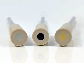
    These single-piece rotating disk electrodes are ideal for applications requiring a high rotation rate (up to 7000 RPM). Each electrode features a 5 mm OD disk sealed inside a 12 mm OD PEEK shroud. Further information and purchase details are available.

    E2M Series FastSpeed RDEs (PTFE shroud)

    AFE2M050PT.png

    icon_caution.jpg

    CAUTION:

    Maximum Rotation Rate:  \textbf{7000 RPM} Do not rotate at rates higher than the maximum rotation rate.

    ATTENTION:

    Vitesse de rotation maximum:  \textbf{7000 TR/MIN} Ne mettez pas l’appareil en rotation à des vitesses supérieures à la vitesse de rotation maximum.


    icon_no_power.jpg WARNING:

    Rotating shaft. Use extreme caution when operating the rotator at rotation rates above  \textbf{2000 RPM} . Always secure the enclosure around the rotator before rotating the electrode (see Figure 4.6).

    AVERTISSEMENT:

    Arbre en rotation. Soyez extrêmement prudent lorsque vous utilisez le rotateur à des vitesses de rotation supérieures à 2000 tr/min. Fixez correctement le boîtier autour du rotateur du rotateur avant de mettre l’électrode en rotation (voir figure 4.6).

    icon_heat.jpgTEMPERATURE LIMITATIONS:

    OPERATING TEMPERATURE RANGE: \textbf{15}\boldsymbol{^\circ} \textbf{C} to \textbf{25}\boldsymbol{^\circ} \textbf{C} Do not use this electrode outside the operating temperature range.

    These single-piece rotating disk electrodes are ideal for applications requiring a high rotation rate (up to 7000 RPM). Each electrode features a 5 mm OD disk sealed inside a 12 mm OD PEEK shroud. Further information and purchase details are available.

    5.5 RRDE Tips

    All RRDE tips have 15 mm OD shrouds made from either PTFE or PEEK. The ring electrode is permanently mounted in the RRDE tip, but the disk electrode may be permanently mounted or removable.

    ChangeDisk RRDE Tips

    E6 Series ChangeDisk RRDE Tips (PTFE shroud)

    RRDE-Tip-E6-Series.jpg

    icon_caution.jpg

    CAUTION:

    Maximum Rotation Rate:  \textbf{3000 RPM} Do not rotate at rates higher than the maximum rotation rate.

    ATTENTION:

    Vitesse de rotation maximum:  \textbf{3000 TR/MIN} Ne mettez pas l’appareil en rotation à des vitesses supérieures à la vitesse de rotation maximum.


    icon_heat.jpgTEMPERATURE LIMITATIONS:

    OPERATING TEMPERATURE RANGE: \textbf{15}\boldsymbol{^\circ} \textbf{C} to \textbf{25}\boldsymbol{^\circ} \textbf{C} Do not use this electrode outside the operating temperature range.

    The E6 Series ChangeDisk RRDE Tips (shroud composed of PTFE) fit the standard RRDE shaft. The electrode disk insert is 5 mm OD and can be removed and replaced with a variety of different materials. A thin, hydrophobic PTFE seal (known as a “U-cup”) surrounds the disk insert when it is mounted in the shroud. Further information and purchase details are available.

    E6PK Series ChangeDisk RRDE Tips (PEEK shroud)

    AFE6R1AU_with_disks.png

    icon_caution.jpg

    CAUTION:

    Maximum Rotation Rate:  \textbf{3000 RPM} Do not rotate at rates higher than the maximum rotation rate.

    ATTENTION:

    Vitesse de rotation maximum:  \textbf{3000 TR/MIN} Ne mettez pas l’appareil en rotation à des vitesses supérieures à la vitesse de rotation maximum.


    icon_heat.jpgTEMPERATURE LIMITATIONS:

    OPERATING TEMPERATURE RANGE: \textbf{10}\boldsymbol{^\circ} \textbf{C} to \textbf{80}\boldsymbol{^\circ} \textbf{C}.

    Do not use this electrode outside the operating temperature range.

    icon_corrosive.jpg

    CHEMICAL INCOMPATIBILITY:

    Shrouds fabricated from PEEK may be discolored by prolonged exposure to concentrated acids.

    The E6PK Series ChangeDisk RRDE Tips (shroud composed of PEEK) fit the standard RRDE shaft. The electrode disk insert is 5 mm OD and can be removed and replaced with a variety of different materials. A thin, hydrophobic PTFE seal (known as a “U-cup”) surrounds the disk insert when it is mounted in the shroud. Further information and purchase details are available.

    Fixed-Disk

    E6R2 Series RRDE Tips

    E6R2-RRDE-side-view.png

    icon_caution.jpg

    CAUTION:

    Maximum Rotation Rate:  \textbf{3000 RPM} Do not rotate at rates higher than the maximum rotation rate.

    ATTENTION:

    Vitesse de rotation maximum:  \textbf{3000 TR/MIN} Ne mettez pas l’appareil en rotation à des vitesses supérieures à la vitesse de rotation maximum.


    icon_heat.jpgTEMPERATURE LIMITATIONS:

    OPERATING TEMPERATURE RANGE: \textbf{10}\boldsymbol{^\circ} \textbf{C} to \textbf{80}\boldsymbol{^\circ} \textbf{C}.

    Do not use this electrode outside the operating temperature range.

    icon_corrosive.jpg

    CHEMICAL INCOMPATIBILITY:

    Shrouds fabricated from PEEK may be discolored by prolonged exposure to concentrated acids.

    The E6R2 Series RRDE Tips (shroud composed of PEEK) fit the standard RRDE shaft. The electrode disk is 5.5 mm OD, and there is a thin, hydrophobic PTFE gap between the permanently mounted disk and ring electrodes. Further information and purchase details are available.

    E7 Series ThinGap RRDE Tips

    AFE7R8PTPT_angled_001.jpg

    icon_caution.jpg

    CAUTION:

    Maximum Rotation Rate:  \textbf{3000 RPM} Do not rotate at rates higher than the maximum rotation rate.

    ATTENTION:

    Vitesse de rotation maximum:  \textbf{3000 TR/MIN} Ne mettez pas l’appareil en rotation à des vitesses supérieures à la vitesse de rotation maximum.


    icon_heat.jpgTEMPERATURE LIMITATIONS:

    OPERATING TEMPERATURE RANGE: \textbf{15}\boldsymbol{^\circ} \textbf{C} to \textbf{25}\boldsymbol{^\circ} \textbf{C} Do not use this electrode outside the operating temperature range.

    The E7 Series ThinGap RRDE Tips (shroud composed of PTFE) fit the standard RRDE shaft. They feature a thin PTFE gap (180 or 320 micrometer) between the permanently mounted disk and ring electrodes. Further information and purchase details are available.

    5.6 RCE Tips

    15 mm OD RCE Tips

    Complete rotating cylinder electrode (RCE) systems for the MSR rotator are available. These systems use a  \text{15 mm} diameter cylinder geometry.

    A typical  \text{15-mm OD} RCE system includes a  \text{15 mm OD} RCE shaft, a one liter corrosion cell equipped with a center-port gas-purged bearing assembly, a means of heating the contents of the cell, and other accessories.

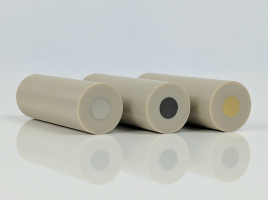
    The RCE shaft accepts standard cylinder samples ( \text{15 mm OD} \times \text{6.3 mm} tall) fabricated from carbon steel or various stainless steels.

    RCE15_overview.jpg

    icon_caution.jpg

    CAUTION:

    Maximum Rotation Rate:  \textbf{4000 RPM} Do not rotate at rates higher than the maximum rotation rate.

    ATTENTION:

    Vitesse de rotation maximum:  \textbf{4000 TR/MIN} Ne mettez pas l’appareil en rotation à des vitesses supérieures à la vitesse de rotation maximum.


    icon_heat.jpgTEMPERATURE LIMITATIONS:

    OPERATING TEMPERATURE RANGE: \textbf{10}\boldsymbol{^\circ} \textbf{C} to \textbf{80}\boldsymbol{^\circ} \textbf{C} Do not use this electrode outside the operating temperature range.

    Further information and purchase details are available.

    12.0 mm OD RCE Tips

    Legacy users of  \text{12 mm} RCE systems are encouraged to begin working with the newer  \text{15 mm} RCE geometry; however, the  \text{12 mm} geometry remains available.

    RCE-Tip-12-mm-OD-fixed.jpg

    icon_caution.jpg

    CAUTION:

    Maximum Rotation Rate:  \textbf{2000 RPM} Do not rotate at rates higher than the maximum rotation rate.

    ATTENTION:

    Vitesse de rotation maximum:  \textbf{2000 TR/MIN} Ne mettez pas l’appareil en rotation à des vitesses supérieures à la vitesse de rotation maximum.


    icon_heat.jpgTEMPERATURE LIMITATIONS:

    OPERATING TEMPERATURE RANGE: \textbf{15}\boldsymbol{^\circ} \textbf{C} to \textbf{25}\boldsymbol{^\circ} \textbf{C} Do not use this electrode outside the operating temperature range.

    Legacy 12 mm OD RCE tips accept cylinder inserts fabricated from carbon and stainless steel (shroud composed of PTFE, other inserts available upon request) and fit the standard RDE/RCE shaft. Further information and purchase details are available.

    Read More
  • Storage and Shipment

    In the event that the rotator system is not going to be used for a long period of time, it should be stored in the original packaging material to prevent damage. It should be stored at temperatures between -17^\circ C and 37^\circ C, and at humidity levels less than 95\% non-condensing.
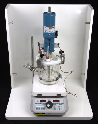
    Retain the original packing materials for future use. These packing materials were designed to provide both protection in shipment, and to minimum size and weight for efficient shipment.

    Read More
  • Troubleshooting

    This section describes some basic troubleshooting considerations when working with a rotator. Each of the basic problems is represented in a toggle below with suggested cause or action that should be taken. If problems with the rotator persist, contact the factory for further assistance (see Section 1.5).

    No Rotation

    If the rotator is not rotating, consider the following:

    • Confirm that the unit is connected to a live power outlet.
    • Confirm that the power switch has not tripped and that it is in the “on” position. Reset the switch if necessary.
    • Check the front panel circuit breaker and reset the breaker if necessary.
    • Check the motor control cable which connects the control unit to the motor unit. The connectors at both ends of this cable must be secured using the two screws on each connector.
    • The rotation rate knob may be set to full counterclockwise position. If this is the case, then rotate the knob clockwise to increase the rotation rate.
    • The motor, the shaft or one of the bearings may be frozen due to corrosion, or one of the boards or cables may be loose. Turn off the rotator, disconnect power, and then try the following procedure:

      icon_caution.jpg WARNING:

      Risk of electric shock.
      Disconnect all power before servicing the rotator.

      AVERTISSEMENT:

      Risque de décharge électrique.
      Déconnectez toutes les sources d’alimentation avant de procéder à l’entretien du rotateur.

      Check for freedom of rotation of the shaft by manually attempting to rotate the shaft.
      Look inside the control unit and confirm that the printed circuit board is fully inserted into its connector.

    Continuous Rotation at a High Rate

    If the rotator is continuously rotating at a high rate, consider the following:

    • Check the motor control cable which connects the control unit to the motor unit. The connectors at both ends of this cable must be secured using the two screws on each connector.
    • Faulty connection or wire – contact the factory.
    • Faulty circuitry – contact the factory.

    System Power Loss

    If the rotator experiences a system power loss, consider the following:

    • The main power switch on the back panel is a circuit breaker which may trip and cause the system to lose power. To reset the breaker, turn the switch off and then turn the switch on again. Repeated tripping may indicate a more serious problem.

    Front Panel Circuit Breaker Trips

    If the front panel circuit breaker trips, consider the following:

    • This breaker only trips if the current passing through the motor windings is high enough to potentially damage the motor. This could occur if the electrode is spinning in a particularly viscous liquid, if the shaft is rubbing against something, or if an applied periodic waveform controlling the rotation rate has too great an amplitude or frequency.
      This breaker (thermal type) is sized to limit the average motor current to within the motor specification. Running the motor at a high modulation frequency, or with large amplitude changes, or a combination of the two, may cause tripping. It may be necessary to reduce the modulation frequency and/or amplitude to prevent tripping of the breaker.
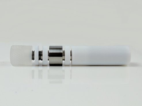
    Rotator Spins Backward

    If the rotator is spinning backward, consider the following:

    • When the rotation rate knob is in the full counterclockwise position, it is natural to expect that the rotation rate should be exactly zero. However, it is normal for there to be a small residual rotation rate, and often this is in the reverse direction.
    • If a negative voltage signal is applied to the INPUT jacks on the front panel of the control unit, then the rotator will spin backwards. If this is undesirable, reverse the polarity of the signal applied to the INPUT jacks.

    Excessive Audible Noise

    If the rotator is excessively loud, consider the following:

    • If the rotator has a standard lower bearing assembly with a stainless steel bearing, then this bearing may be corroded. If corroded, replace the entire lower bearing assembly.
    • Internal spindle bearings are worn – contact the factory.

    Electrical Noise in Voltammograms

    Electrical noise in voltammograms can be caused by a number of factors. Broadly, these factors are categorized as environmental, grounding issues, brush wear, and cell connections. They are discussed separately below.

    Environmental

    Environmental electrical noise can be solved by checking the following:

    • Make sure that working, reference, and counter electrode cables do not cross or travel near power cords, video cables, or network lines.
    • Make sure that the potentiostat and rotator are located as far as possible from hotplates, ovens, video monitors, computers, network hubs, wireless devices, or cellular telephones.

    Grounding Issues

    Electrical noise caused by grounding issues can be solved by referencing Section 4.5 and by checking the following:

    • Confirm that the earth ground connection on the rotator is connected to the chassis ground of the potentiostat.
    • Confirm that all metal objects (such as cell clamps and ring stands) near the electrochemical cell are connected to the earth ground connection on the rotator.
    • Confirm that all grounding connections are made to a common grounding point to avoid the formation of “grounding loops”. Note that grounding loops are sometimes non-obvious, especially when multiple instruments and computers are connected together.

    Brush Wear

    Electrical noise caused by brush wear can be resolved by doing the following:

    • Always use a banana jumper cable to connect opposing brushes together. Two brushes in opposing contact provide a better electrical connection.
    • Inspect all brush contacts. Brushes should have a concave groove worn in them which exactly mates with the rotating shaft. The depth of this concave groove naturally increases over the lifetime of the brush. A new brush should be worn continuously for approximately eight hours to intentionally wear a groove into the brush to increase the surface area of the brush that is in contact with the shaft.

    Cell Connections

    Electrical noise caused by cell connection issues can be resolved by doing the following:

    • Confirm that the reference electrode has low impedance and is in good contact with the main test solution. High impedance at the reference electrode is often caused by a plugged frit, which impedes current between the inner chamber of the reference electrode and the main test solution. High impedance may also be encountered when working with low dielectric media (such as non-aqueous solvents).
    • Use working, reference, and counter electrode cables which are shielded (coaxial) cables.
    • Confirm that any alligator clips being used for connection to the electrodes are not corroded and are securely fastened to the electrodes.
    • Note that many potentiostats utilize a driven shield to protect the reference electrode signal. This driven shield is connected to the outer shield line in the coaxial reference electrode cable. Only the inner signal line of the coaxial cable should be connected to the reference electrode. The outer shield line should not be connected to anything at the cell end of the cable. Do not ground such a driven shield line as it may cause the potentiostat to oscillate or malfunction.
    Read More
  • Installation

    Table of Contents

    3.1 Site Preparation

    The rotator system should be located on a sturdy table or laboratory bench with ample clearance around the perimeter of the rotator enclosure. The front of the rotator should be unobstructed, and there should be at least  \text{20 cm} clearance on each side and behind the rotator, for a total table space of  \text{(40 cm} \times \text{60 cm)} . The location should also include enough space for the control unit  \text{(30 cm} \times \text{30 cm)} and vertical clearance to easily raise and lower the motor unit.

    3.2 Unpacking and Setting Up the Rotator

    icon_info.jpgNOTE:

    The numbers in parentheses in the installation instructions (below) correspond to the numbering used in the tables and figures found in Section 2 of this manual.

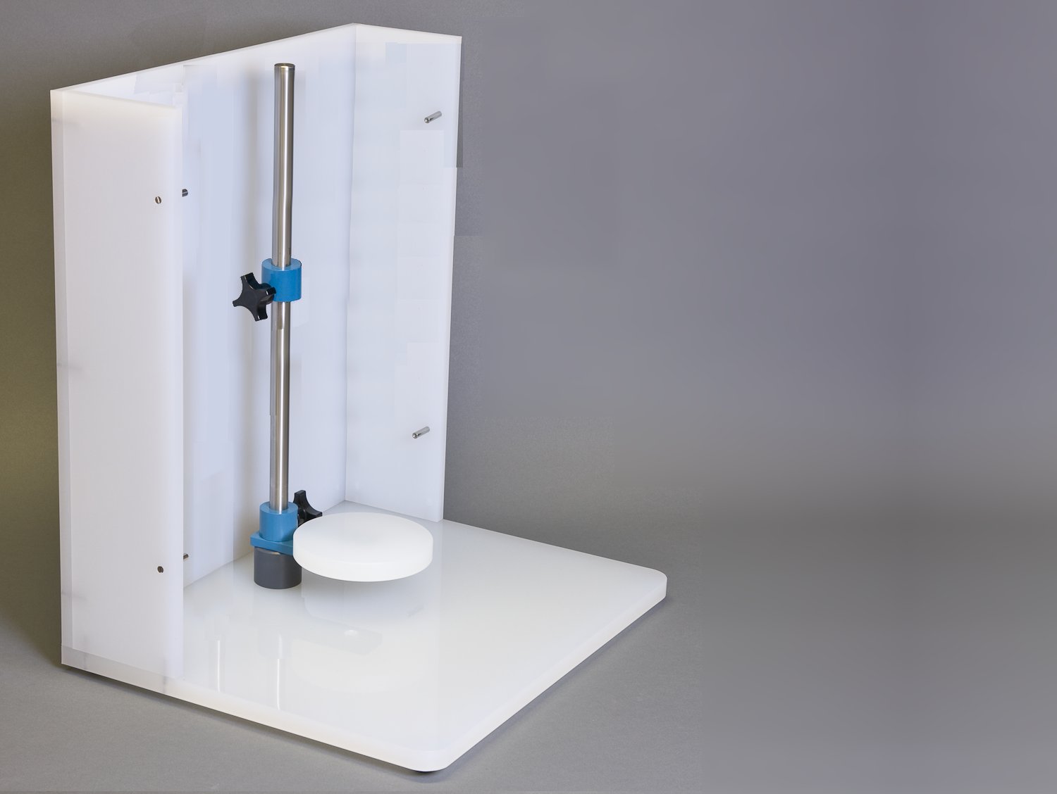
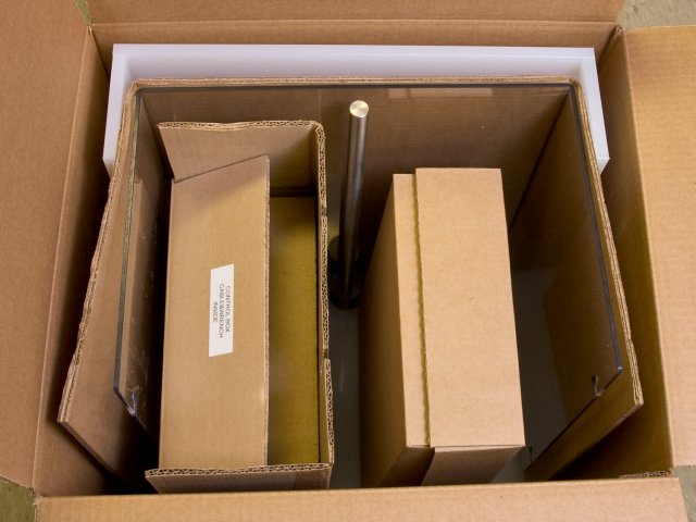
    1. Inspect the contents of the shipping carton. Remove the top piece of cardboard to reveal the two smaller boxes in the carton. The control unit (10) is packed inside the larger box, and the smaller box holds additional components. Remove both boxes and set aside. Then, carefully remove the enclosure window (7) and the enclosure base (4) from the box. The center post (1) is pre-installed in the enclosure base.
    2. 001-The-Big-Box.jpg
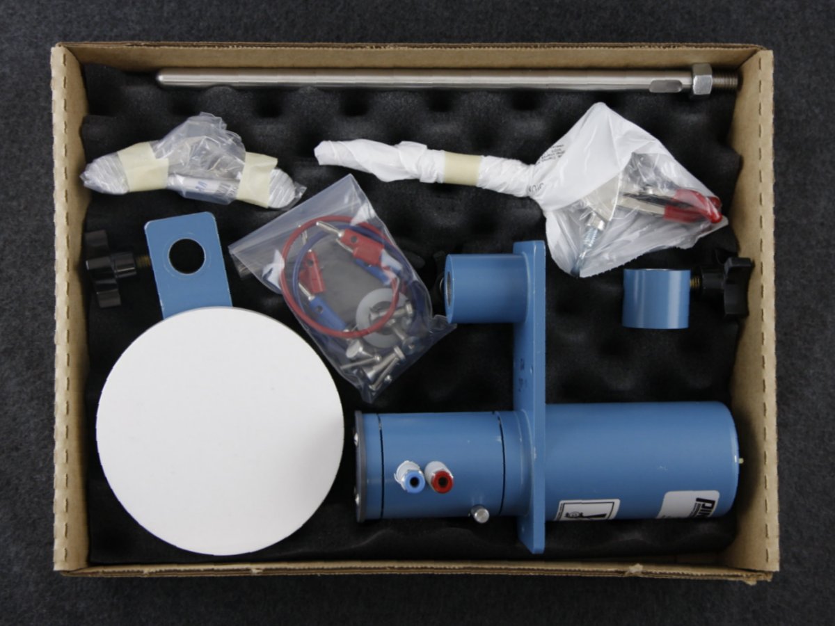
    3. Open the smaller box. It should contain the motor unit (2), the support collar (5), the cell platform (3), the side post (6), a standard three-pronged laboratory clamp (with right-angle mount), and a small bag containing two banana cables and some additional assembly hardware.
    4. 002-The-Little-Box-Pine-version.jpg

      icon_info.jpgNOTE:

      The outer diameter of the side post (6) shown in these photos is  \textbf{5/8" (15.9 mm)} , but in some alternate rotator configurations this diameter may be  \textbf{1/2" (12.7 mm)} .

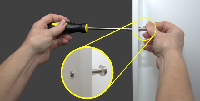
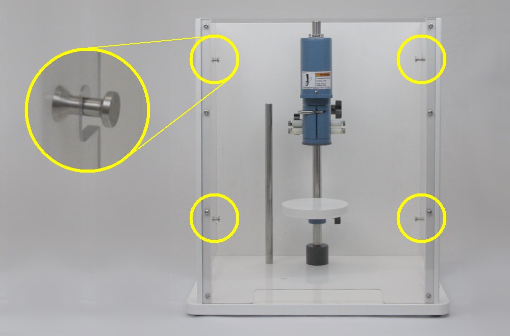
    5. Locate the small bag of hardware. Remove the four pins and four screws. Place each screw in one of the pre-drilled holes along the side walls of the enclosure, two on the left and two on the right. Install the pins onto the screws. Properly installed pins will point inwards as shown.
    6. 003-Dianes-Hands.jpg
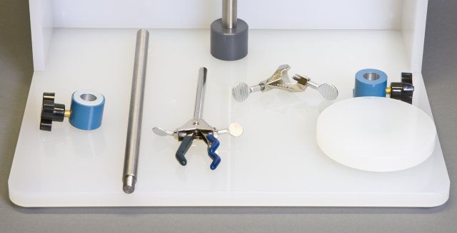
    7. Locate the support collar (5), side post (6), and three-pronged laboratory clamp (with right-angle mount), cell platform (3), and the large plastic washer (usually shipped in the hardware bag).
    8. 004-Pieces-and-Parts.jpg
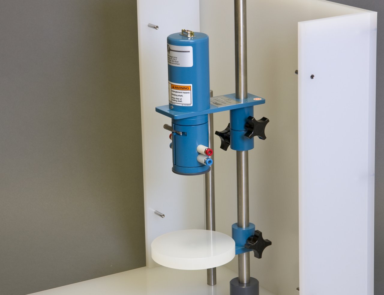
    9. Slide the cell platform (3) onto the center post and position it near the bottom of the center post (1) with the platform facing up. Tighten the knob to secure the cell platform to the center post. Next, slide the support collar (5) on to the center post and position it slightly above the midpoint of the center post with the knob on the left side. Tighten the knob to secure the support collar to the center post. Slide the plastic washer on the center post and allow it to rest on top of the support collar.
    10. 005-Platform-and-Support-Collar.jpg
    11. Carefully slide the motor unit (2) on to the center post (1) until it rests on the support collar (5). Tighten the knob to secure the motor unit to the center post.
    12. 006-Motor-Unit-on-Center-Post-Pine-version.jpg

      icon_info.jpgNOTE:

      The relative vertical positions of the cell platform, support collar, and motor unit may be adjusted as needed to fit the specific size and shape of a particular electrochemical cell.

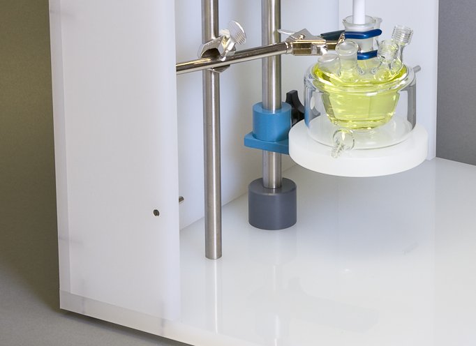
    13. There are several holes in the floor of the enclosure base (4), which are threaded to accept the side post (6). Choose one of these holes and install the side post in it. Then, mount the laboratory clamp on to the side post.
    14. 007-Clamped-Glass-Cell.jpg
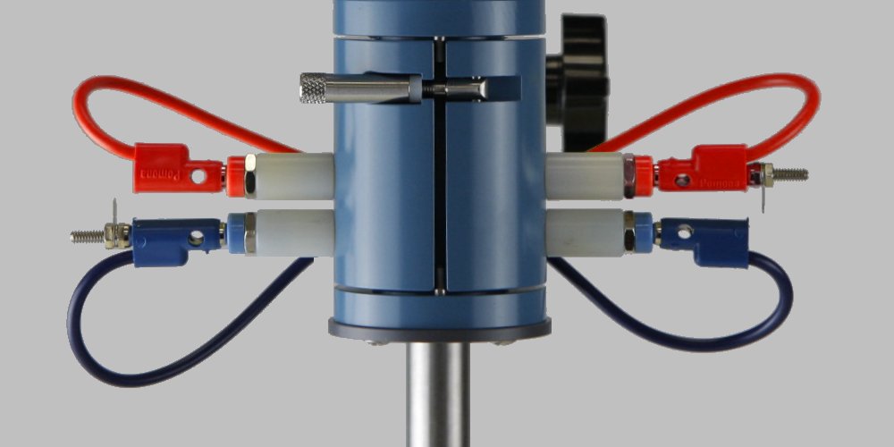
    15. There are two short banana cables (red and blue) which serve as jumpers between the left and right brush connections. Use the red cable to connect the upper (red) pair of brush connections, and use the blue cable to connect the lower (blue) pair of brush connections, running the wires behind the assembly as shown.
    16. 008-Banana-Jumpers-Pine-version.jpg
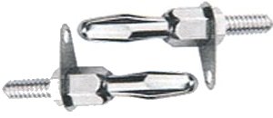
    17. Insert one banana plug stud into the red banana cable, and insert the other banana plug stud into the blue banana cable. These flat studs are an ideal place to make connections using alligator clips.

      The upper (red) jacks make electrical contact with a rotating disk electrode (RDE) or a rotating cylinder electrode (RCE) tip.

      When using a rotating ring-disk electrode (RRDE), the upper (red) jacks make contact with the disk, and the lower (blue) jacks make contact with the ring.
    18. 009-Double-Banana-Studs.jpg   010-Stud-in-Place-Pine-version.jpg
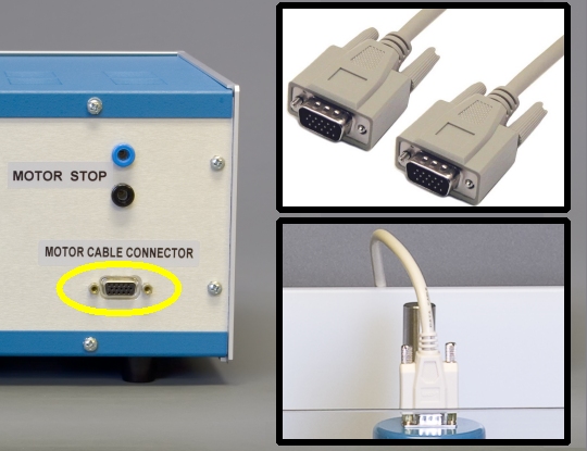
    19. Remove the control unit (10) from the box and place it next to the enclosure base. Plug the male end of the motor control cable (8) into the motor cable connector on the back of the control unit, and plug the female end of the cable into the top of the motor unit.
    20. 011-Motor-Cable-Connection.jpg


      icon_caution.jpg

      CAUTION:

      The connectors on both ends of the motor control cable MUST be firmly secured by tightening the pair of screws on each connector.
      Failure to secure the connectors will result in improper control of the rotation rate.

      ATTENTION:

      Les connecteurs situés aux deux extrémités du câble de commande du moteur DOIVENT être fermement attachés en serrant les deux vis de chaque connecteur.
      Une mauvaise fixation des connecteurs entraînera un mauvais contrôle de la vitesse de rotation.

    21. Attach the enclosure by hooking it on to the four pins. The enclosure will rest securely on the enclosure base.
    22. Figure-4.6-The-Enclosure.jpg
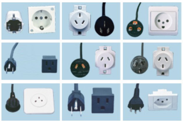
    23. An appropriate power cord (10 amp rating) is provided with the rotator. Use this cord to connect the control unit to the local power supply.

      The local power supply should provide an earth ground connection for the third prong on the power cord.

    24. 012-Power-Cords.jpg

    electric_shock.png

    WARNING:

    Failure to connect the third prong of the power cord to a proper earth ground may impair the protection provided by the system.

    AVERTISSEMENT:

    L’absence de connexion de la troisième broche du cordon d’alimentation à une prise de terre appropriée peut altérer la protection fournie par le système.

    electric_shock.png

    CAUTION:

    A detachable main power cord is provided with the rotator. Do not replace this cord with an inadequately rated cord.

    ATTENTION:

    Un cordon d’alimentation amovible est fourni avec le rotateur. Ne remplace pas ce cordon par un cordon de calibre inadéquat.

    Read More
  • Non-Faradaic Current

    This article has not been created.

    Read More
  • Migration

    This article has not been created

    Read More
  • Electroactive

    This article has not been created.

    Read More
  • Diffusion

    This article has not been created.

    Read More