1Abstract
An inert atmosphere is usually defined as the absence of oxygen from an electrochemical cell. Sometimes, an inert atmosphere also refers to the absence of both oxygen and water, especially when the redox molecules of interest are moisture sensitive. Air contains both oxygen and water. Thus, methods for preparing and maintaining an inert atmosphere are largely about removing air from an electrochemical experiment. Two techniques, namely, the benchtop technique and the glovebox technique, will be introduced, and their practical limitations discussed.
2Inert Atmospheres Free of Oxygen and Water
Oxygen and water often participate in unwanted redox or hydrolysis reactions in an electrochemical cell (see Sections 2.1 and 2.2). For this reason, many electrochemical experiments need to be performed in the absence of air which contains both oxygen and water. This section will discuss electrochemistry of oxygen and water and the subsequent sections then outline the specific techniques utilized to conduct electrochemical experiments in an inert or air-free atmosphere.
2.1Oxygen as an Electroactive Species
Oxygen can be electrochemically reduced, and the reduction is often catalyzed by metal-containing compounds. For example, in the absence of oxygen, iron 5, 10, 15, 20-meso-tetraphenylporphyrin chloride, [FeIII(TPP)Cl], undergoes reversible reduction from iron(III) to iron(II) in a HClO4 solution (see Figure 1, black trace). However, in the presence of oxygen, [FeIII(TPP)Cl] catalyzes the reduction of oxygen instead (see Figure 1, red trace).
![Cyclic Voltammograms of [Fe^III (TPP)Cl] in a HClO_4 Solution in the Absence (black) and Presence (red) of Oxygen.](https://www.pineresearch.com/shop/wp-content/uploads/sites/2/2019/01/DRA10072-fig-1.jpg)
Figure 1. Cyclic Voltammograms of [FeIII (TPP)Cl] in a HClO4 Solution in the Absence (black) and Presence (red) of Oxygen. *Adapted with permission from Wasylenko et al. J. Am. Chem. Soc. 2014, 136, 12544−12547. Copyright 2014 from the American Chemical Society
Because of interference from oxygen reduction, studying the redox chemistry of [Fe
III(TPP)Cl] itself can be challenging. Oxygen is thermodynamically easy to reduce (E
0 = 1.2 V vs NHE, see equation below), but the reaction is kinetically slow. However, many redox active molecules of interest will react with oxygen (as was the case for [Fe
III(TPP)Cl] above), and the net result is that molecules of interest act as a catalyst for the kinetically slow oxygen reduction.
Some common side effects of oxygen interference are electroactive byproducts, shifts in redox potential, new peaks or absence of peaks, and overall distortion of data.
2.2Water as an Electroactive Species
Water is a common solvent for electrochemical experiments due to its ubiquity and polarity, allowing the use of a variety of electrolytes with a large ionic conductivity. Still, many researchers need to use organic solvents because they provide a wider electrochemical window, aprotic conditions, and high solubility/stability for many organometallic or air-sensitive compounds.
Water can be oxidized to produce oxygen at extreme anodic potentials and reduced to produce hydrogen at extreme cathodic potentials. In addition, water can react with many synthetic compounds in unwanted hydrolysis reactions. Thus, success of electrochemical experiments in organic solvents often depends on minimizing proton availability, which requires removal of any extraneous water from the sample electrolyte.
NOTE: For some electrochemical studies, water is the solvent and does not participate in unwanted hydrolysis reactions. Therefore, an inert atmosphere free of oxygen is sufficient in these studies, and it is not necessary to eliminate both oxygen AND water.
2.3Brief Overview of Air-Free Electrochemistry
2.3.1Two Techniques for Inert Atmosphere Experiments
Electrochemical experiments in an inert atmosphere can be performed either on the benchtop or within a glovebox (see Sections 3 and 4, respectively). Conducting an electrochemical experiment in the absence of oxygen is much simpler than in the absence of water. Removing oxygen can often be done on a benchtop and only requires simple purging or blanketing of the sample electrolyte with an inert gas such as nitrogen or argon. In comparison, water-free experiments require high purity anhydrous solvents that can be produced only by expensive solvent purification and delivery systems. In addition, a glovebox is often required to maintain the purity of the anhydrous solvent during its storage and use. Prior to the introduction of an anhydrous solvent to glovebox, a sequence of steps called freeze-pump-thaw are often performed to remove oxygen dissolved in the solvent. This article assumes that solvents of desired anhydrous purity and free of oxygen are already available, and will limit discussions to how to maintain that anhydrous purity and how to remove oxygen from the electrochemical cell.
2.3.2Electrochemical Cell Used in this Article
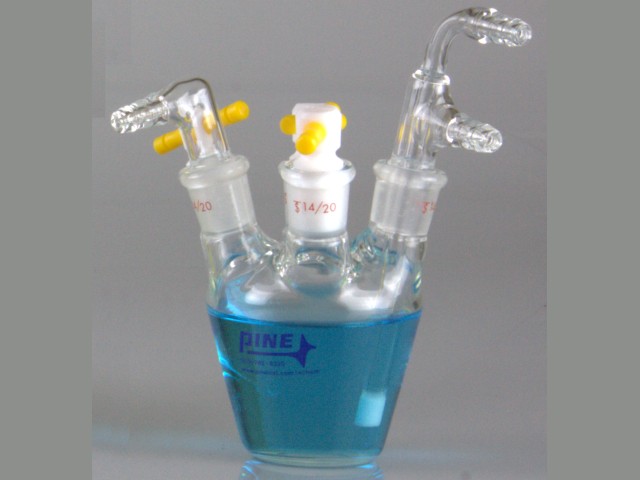
Pine Research offers electrochemical cells of various sizes to fulfill customers’ needs. The Standard Voltammetry Cell (part number AKCELL1, see Figure 2)
is ideal for conducting electrochemical experiments in an inert atmosphere. The five 14/20 ground glass ports allow air-tight attachment of working, counter, and reference electrodes. The Standard Voltammetry Cell includes five polytetrafluoroethylene (PTFE) stoppers and purging accessories for creating and maintaining an inert atmosphere. Directions in this document will specifically reference the Standard Voltammetry Cell, but they are also applicable to other cells.
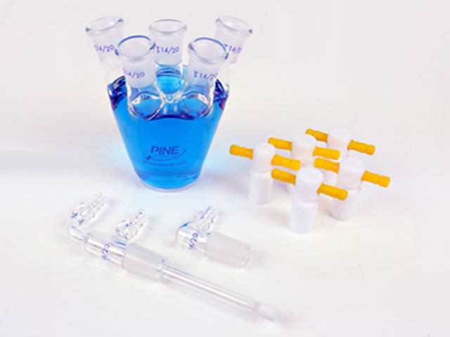
Figure 2. Standard Three-Electrode Cell with Stoppers and Glass Sparge/Purge Accessories
3Creating an Inert Atmosphere on the Benchtop
Oxygen-sensitive electrochemical experiments are performed on the benchtop for a variety of reasons: a glovebox is unavailable; it is not critical to remove water (e.g., water is the solvent); or it is much convenient to set up and manipulate the electrochemical cell outside a cumbersome glovebox. This section will describe how to remove oxygen and maintain an inert atmosphere over the course of the entire experiment. Three types of benchtop experiments will be discussed: water-insensitive experiments, water- sensitive experiments, and concentration-sensitive experiments.
3.1Water-Insensitive Experiments
3.1.1Setting Up the Electrochemical Cell
Setting up an electrochemical cell to perform experiments under an inert atmosphere is very similar to setting up other electrochemical experiments, except that the cell needs to have inlet and outlet ports for purging and maintaining inert gas in the sample electrolyte. To set up the cell, fill the Standard Voltammetry Cell with the sample electrolyte, and then insert the working (a), reference (b), and counter (c) electrodes with their respective 14/20 adapters into the 14/20 ground glass ports (see Figure 3). Make sure that the electrolyte fully covers each electrode before attaching the cell cable. Grease the Dual Port Gas Inlet (d) and Single Port Gas Outlet pieces (e) and place them in the remaining 14/20 ports. Be sure to rotate the gas ports to create a good seal, and secure the seal with Keck clips (see Figure 3). Connect both hose barb connectors on the Dual Port Gas Inlet (d) to an inert gas source (e.g., a nitrogen or argon tank). Do not turn the inert gas source on yet.
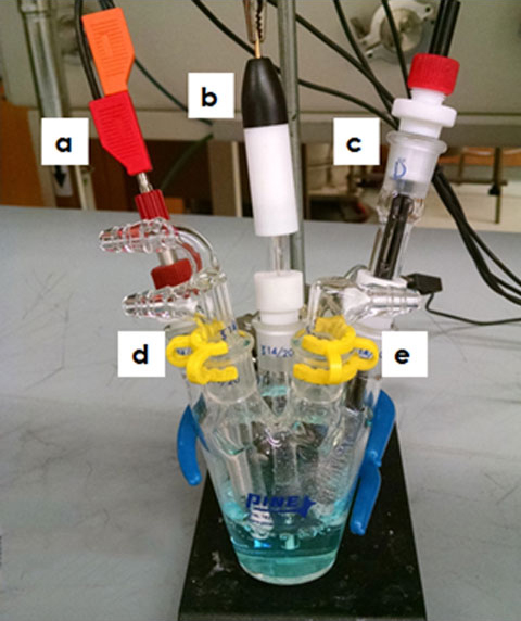
Figure 3. Water-Insensitive Electrochemical Cell Setup
3.1.2Creating an Inert Atmosphere in the Electrochemical Cell
The top hose barb connector on the Dual Port Gas Inlet is connected to the frit for bubbling while the bottom hose barb to the headspace of the cell for blanketing (see Figure 4). Before introducing inert gas to the cell, make sure that there is an open outlet port; without an outlet, gases will build up in high pressure and be forced to escape through an undesirable route or explosion. Slowly turn on the inert gas to the fritted tube; gas bubbles will appear in solution. Bubble the inert gas through the solution at a desirable rate. For most experiments, a rapid purge (but not so rapid that solution is spilling, see Figure 4) is used for about three minutes to completely displace dissolved oxygen. At the same time that the solution is bubbling, turn on the inert gas to the headspace to displace oxygen and blanket the inert gas over the sample electrolyte surface. To remove the last trace of oxygen, purge both gas lines at a medium flow rate with the inert gas for an additional ten minutes.
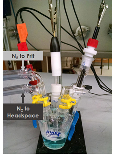
Figure 4. Purging the Electrochemical Cell
3.1.3Testing that the Atmosphere is Inert
To test if oxygen is completely removed, purge a blank electrolyte solution as described in Section 3.2, and then turn off the inert gas to the fritted tube so that the solution stops bubbling. Next, perform a two-segment background cyclic voltammogram with the initial potential set to the maximum potential limit of the solvent window and the vertex potential set to the minimum limit. If the resulting voltammogram is relatively flat and featureless within the solvent window, then oxygen is not present. On the other hand, if a cathodic peak appears in the voltammogram during the first segment, it is likely that oxygen is still present. In this case, increase the purge time and/or the flow rate as described in Section 3.2.
3.1.4Adding the Analyte
Schlenk line techniques can be used to add solid analyte to the electrochemical cell. First, turn up the flow of inert gas to the headspace. Then, remove one of the electrodes, and drop the solid through the open port. The extra flow of inert gas through the cell should maintain the inert atmosphere inside the cell while you add the solid analyte. If the analyte is a liquid solution, still add through the open port but then remove any dissolved oxygen by purging through the frit for additional ten minutes as described in Section 3.2.
3.1.5Maintaining the Inert Atmosphere
Once the electrochemical cell is air-free, maintain its atmosphere by following two main steps. First, the bottom port on the Dual Port Gas Inlet, which supplies fresh, inert gas for blanketing over the sample electrolyte, should never be closed during the entire course of the electrochemical experiment. Second, if the experiment permits, bubble inert gas through the electrolyte from the frit, particular during times between electrochemical measurements. Doing both of these things will keep the electrochemical cell under a very good inert atmosphere.
TIP: If one of the hoses that connects the inert gas source to the Dual Port Gas Inlet breaks free, first make sure that the other hose is secure and has inert gas flowing to the cell. Then, purge the hose that broke free with inert gas for about one minute before reconnecting the hose to the electrochemical cell.
3.1.6Practical Limitations
The procedure outlined for Water-Insensitive Experiments in Sections 3.1.1—3.1.5 does not protect the analyte from oxygen or water during the cell setup. If the analyte needs to be protected from oxygen at all times, please use the procedures outline in Section 3.2 or Section 4. While both nitrogen and argon are common inert gases, we recommend argon as the inert gas source on the benchtop. Argon has a higher density than nitrogen, and hence is more effective in masking the headspace within the electrochemical cell. Using nitrogen as the inert gas source is acceptable, but the researcher should be mindful to have a steady nitrogen flow from one end of the cell to the other at all times. Finally, if a volatile solvent is used for electrochemical experiments, it will likely evaporate when the solution is being purged. More solvent can be added and purged again to circumvent this issue. However, if precise analyte concentration is needed, another experimental procedure will need to be utilized (see Section 3.3).
INFO: If the analyte under study is both oxygen and water sensitive, it is best to perform the experiments in a dry glovebox under inert atmosphere.
3.2Water-Sensitive Experiments
3.2.1Setting up the Electrochemical Cell
For a water-sensitive experiment, it is best to prepare the solution inside a dry glovebox under inert atmosphere. If experiments must be done outside the glovebox, there are a couple options to keep the cell air-free. The first and easiest option is to prepare the working, reference, and counter electrodes inside a glovebox and attach them to the Standard Voltammetry Cell with the 14/20 adapters as discussed in Section 3.1.1. Then, instead of attaching the gas inlet and outlet ports, plug the remaining 14/20 ground glass joints with greased PTFE stoppers (see Figure 5). Then the whole electrochemical cell can be transported out of the glovebox without being exposed to air.
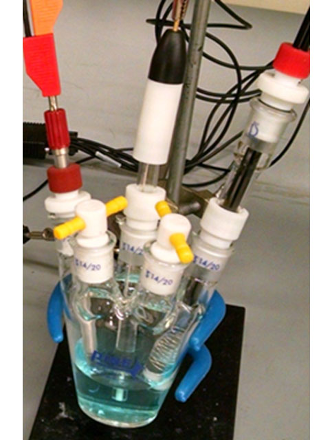
Figure 5. Standard Voltammetry Cell with PTFE Stoppers
A second option for researchers without a glovebox is to dry the electrolyte solution by placing an excess amount of calcium chloride (or other drying agents) directly into the electrochemical cell. With the excess calcium chloride remaining in the cell throughout the experiment, a dry analyte could be added and the rest of the cell could be set up as in Section 3.1.1. This method is not preferred as the analyte will be exposed to air moisture during the transfer unless extensive Schlenk techniques are used.
3.2.2Maintaining the Inert Atmosphere and Practical Limitations
The PTFE stoppers and 14/20 adapters for the electrodes are designed to seal the cell from outside conditions. However, even the best manufacturing and designs cannot completely seal a cell for an indefinite period of time. Practically, the setup depicted in Figure 5 is considered “safe” from outside sources for about one day after it was sealed off. If more than one day is needed to perform the electrochemical measurements, the PTFE stoppers in Figure 5 should be replaced with Schlenk adapters during the setup in Section 3.2.1 and Schlenk techniques should be used to maintain an inert atmosphere within the cell.
3.3Concentration-Sensitive Experiments
3.3.1Setting up the Electrochemical Cell
For concentration-sensitive experiments under an inert atmosphere, the inert gas can be pre-saturated with solvent vapor in order to reduce solvent loss in the electrochemical cell during the procedure described in Section 3.1.1. In this case, the Dual Port Gas Inlet is connected to a Schlenk flask where the inert gas bubbles through appropriate solvent to be pre-saturated with solvent vapor (see Figure 6).
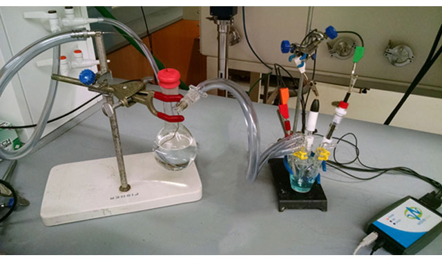
Figure 6. Concentration-Sensitive Electrochemical Cell Setup
A three-way valve can be used for directing pre-saturated inert gas from the Schlenk flask to the frit for bubbling, or to the headspace for blanketing, or to both inert gas inlets. If a three-way valve is not available, then two Schlenk flasks can be used instead. To construct the apparatus in Figure 6, you need a Schlenk flask (a), luer lock needle (b), luer lock tube fitting adapter (c), glass stopcock (d), septa (e), spring (f) and pin (g) suitable for the Schlenk flask (see Figure 7). Assemble the Schlenk flask (a) by greasing the glass stopcock (d) and inserting it through the appropriate ground glass port. Rotate the stopcock to create a good seal and secure it in place with the spring (f) and pin (g). Place solvent in the Schlenk flask and cap it with a septa (e). Connect the luer lock needle (b) to the luer lock tube fitting adapter (c) and inert gas tubing. Push the luer lock needle (b) through the septa (e) and into solution (see Figure 6 for full assembly).
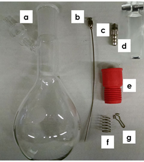
Figure 7. Schlenk Flask Components for Pre-Saturating the Inert Gas with Solvent Vapor. (a) Schlenk Flask; (b) Luer Lock Needle; (c) Luer Lock Tube Fitting Adapter; (d) Glass Stopcock; (e) Septa; (f) Spring; and (g) Pin
3.3.2Creating, Testing, and Maintaining an Inert Atmosphere in the Electrochemical Cell
CAUTION: Before proceeding, make sure that the glass stopcock connecting the Schlenk flask to the electrochemical cell is open. Turning on the inert gas source while the stopcock is closed will build pressure in the Schlenk flask, leading to the septa and needle bursting off. Also check the electrochemical cell to ensure that the outlet is open.
The procedure for creating, testing, and maintaining an inert atmosphere for concentration-sensitive experiments is very similar to that discussed for Water-Insensitive Experiments (see Section 3.1), except that the solvent in the Schlenk flask also needs to be purged with inert gas to remove dissolved oxygen. The main consequence of having to purge the Schlenk flask is that it takes longer to completely deoxygenate the system. To expedite the purging process, it may be desirable to rapidly purge the Schlenk flask first and then purge the electrochemical cell. Altogether, it may take five minutes longer to completely purge the setup.
3.3.3Practical Limitations
Ideally, pre-saturated solvent in the inert purge gas should replace exactly the solvent lost due to bubbling or blanketing. In other words, the rate of solvent molecules entering into the electrochemical cell should be the same as the rate of solvent molecules leaving the cell. In practice, maintaining the amount of solvent in the sample electrolyte to an exact constant level is difficult. Thus, adding the Schlenk flask before the electrochemical cell is useful when small changes in concentration are acceptable (e.g., 5 mM vs 5.1 mM over the course of an hour). If concentration needs to be achieved at a higher accuracy, then the electrochemical cell should be prepared inside a glovebox and fully capped.
INFO: The electrochemical cell can be weighed on an accurate balance before and after an experiment to see if solvent has evaporated.
4Conducting Electrochemical Experiments in the Glovebox
Electrochemical experiments are often performed in a glovebox under inert atmosphere because the analyte is extremely air-sensitive. This section will describe in details the necessary accessories (not included with Pine Research potentiostat bundles) to perform an electrochemical experiment inside a glovebox and practical limitations.
4.1Necessary Accessories to Perform Electrochemical Experiments in a Glovebox
To use a potentiostat inside a glovebox, it is necessary to have all appropriate equipment (potentiostat, cables, electrochemical cell, computer, power cords, etc.) within the glovebox, or there must be glovebox feedthroughs that allow connection to electronic equipment outside the glovebox. Two primary feedthroughs are required to connect to a potentiostat outside the glovebox: the cell cable feedthrough and the USB cable feedthrough.
4.1.1Cell Cable Feedthrough
Feeding the cell cable directly into the glovebox requires that there exists a sufficient seal around the cable to keep the glovebox air-free. A KF-40 flange and epoxy can be used to seal around individual signal lines (see Figure 8). A Faradaic shield in the form of an electric mesh may need to be installed on the cell cable to minimize electrical noise as the cable enters the glovebox. Contact Pine Research for further details.
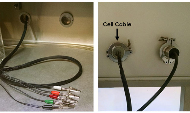
Figure 8. Cell Cable Feedthrough Based on KF Flange: Views from Inside (left) and Outside (right) the Glovebox
4.1.2USB Cable Feedthrough
If the entire potentiostat and its cell cable can be brought into the glovebox, then only the feedthrough for a USB cable (to connect to an outside computer) and the AC power are needed. This greatly simplifies glovebox setup, and has the advantage of less noise because cell cable tends to pick up noise as it goes through the glovebox wall. The disadvantage of using potentiostat inside the glovebox is loss of valuable workspace. USB cable feedthroughs can be bought commercially (see Figure 9) or built using a KF-40 flange and epoxy (see Figure 10).
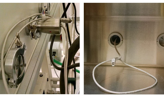
Figure 9. Commercially-Installed USB Cable Feedthrough Based on KF Flange
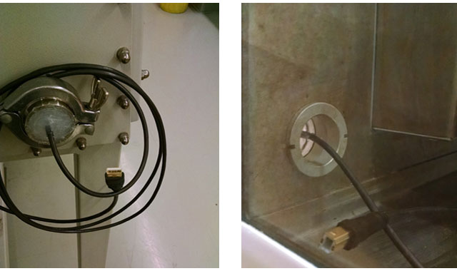
Figure 10. Handcrafted USB Feedthrough Based on KF Flange
4.2Electrochemical Experiments in the Glovebox
4.2.1Setting up and Running the Experiment
All parts to be used in an experiment, such as the working, reference, and counter electrodes, need to be brought into the glovebox first. During the pump down in the antechamber, make sure all removable parts are in their disassembled state. For example, if the counter electrode or the reference electrode come with a fritted tube, the fritted tube should not be mated to the corresponding counter electrode coil or the cap of the reference electrode when in the antechamber. This will ensure thorough pump down of all hidden air pockets. For this reason, traditional aqueous reference electrode such as Ag/AgCl/KCl reference electrode cannot be used, and a special non-aqueous reference electrode, consisting of a silver wire and a fritted tube, has to be introduced into the glovebox first and then assembled into its final form. In addition, all electrolyte solutions, including the main sample electrolyte as well as the electrolyte for constructing the non-aqueous reference electrode, must be free of air and water.
Once all the parts needed in an experiment are brought into the glovebox, setting up the electrochemical cell in the glovebox is straightforward. First, assemble each electrode in its final form. For example, put the 14/20 adapters on all electrodes before inserting them in the desired 14/20 ground glass ports of the Standard Voltammetry Cell. Next, add the anhydrous electrolyte containing the analyte, and connect the cell cable alligator clips to the appropriate electrodes. The solution and atmosphere are already inert, so the setup is complete. Simply run the experiment. To maintain constant concentration over the course of the experiment, plug any unused 14/20 ground glass ports with PTFE stoppers: the setup should look the same as that shown in Figure 5. Otherwise, leave the unused ports unplugged (see Figure 11).
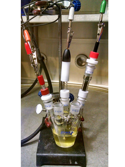
Figure 11. Electrochemical Cell Setup in a Glovebox
4.2.2Practical Limitations
While working in a glovebox is advantageous for air-sensitive electrochemistry, it can be more time consuming. For example, preparation of electrolyte using anhydrous solvent must be done inside the glovebox, which is tedious and cumbersome. Bringing parts needed for an electrochemical experiment in and out of the glovebox also requires extra time. Perhaps the most cumbersome aspect of working in the glovebox is that traditional electrode polishing techniques cannot be used, and so the researcher must exit the glovebox each time the working electrode needs to be polished. Pine Research recommends having multiple working electrodes prepared if working in the glovebox.
5References
-
Wasylenko, D. J. ; Rodríguez, C. ; Pegis, M. L. ; Mayer, J. M. Direct Comparison of Electrochemical and Spectrochemical Kinetics for Catalytic Oxygen Reduction. J. Am. Chem. Soc., 2014, 136(36), 12544-12547.
-
Rountree, E. S.; Dempsey, J. L. Reactivity of Proton Sources with a Nickel Hydride Complex in Acetonitrile: Implications for the Study of Fuel-Forming Catalysts. Inorg. Chem., 2016, 55(10), 5079–5087.


 Standard Electrochemical Cell
is ideal for conducting electrochemical experiments in an inert atmosphere. The five 14/20 ground glass ports allow air-tight attachment of working, counter, and reference electrodes. The Standard Voltammetry Cell includes five polytetrafluoroethylene (PTFE) stoppers and purging accessories for creating and maintaining an inert atmosphere. Directions in this document will specifically reference the Standard Voltammetry Cell, but they are also applicable to other cells.
Standard Electrochemical Cell
is ideal for conducting electrochemical experiments in an inert atmosphere. The five 14/20 ground glass ports allow air-tight attachment of working, counter, and reference electrodes. The Standard Voltammetry Cell includes five polytetrafluoroethylene (PTFE) stoppers and purging accessories for creating and maintaining an inert atmosphere. Directions in this document will specifically reference the Standard Voltammetry Cell, but they are also applicable to other cells.