


General Electrochemistry
Back to General Electrochemistry Back to Applications Back to Knowledgebase HomeGeneral Instrument Grounding Information
Last Updated: 6/17/19 by Neil Spinner
1Grounding Information
The general goal of an experiment grounding strategy is to reduce the level of signal noise in the electrochemical measurement caused by noise sources in the laboratory environment. To avoid issues with laboratory noise sources, it is important to properly ground all metal objects near an electrochemical setup and to make appropriate grounding connections between the potentiostat and any other electronic equipment used as part of the experiment.
1.1Common Noise Sources
A modern laboratory is often full of noise sources that can interfere with the measurement of small amplitude electrochemical signals. Computers, LCD displays, video cables, network routers, network cables, ovens, hotplates, stirrers, and fluorescent lighting are all examples of common laboratory items that may electromagnetically interfere with a delicate electrochemical measurement.
The electrochemical setup, potentiostat, cell cable, and any other experimental equipment (e.g., electrode rotator) should be located as far away from noise sources as possible. It is especially important that the cell cable is located well away from any digital noise sources such as mouse or keyboard cables, network cables, video cables, USB cables, cell phones, etc. The reference electrode cable is particularly sensitive to picking up noise from the environment. Also, any piece of laboratory equipment that intermittently draws a lot of current, such as an oven or hotplate under thermostatic control, should not be powered using the same branch circuit as the potentiostat. When such a piece of equipment goes through a power cycle, it may induce noise or a glitch in the electrochemical measurement.
1.2Grounding Terminology
A potentiostat or other piece of electronic equipment generally has three types of grounding connections that are often confused with one another: the earth ground, the chassis terminal, and the DC Common. These are discussed in more detail below.
1.2.1Earth Ground
 |
EARTH GROUND: |
| An earth ground connection is a direct physical and electrical connection to the Earth. |
An earth ground connection is available in most modern laboratories via the third prong on the power receptacle for the local power system (see Figure 1). The power system infrastructure for a laboratory building usually has a long metal probe buried in the earth, and the third prong of the electrical outlets in the building wiring is connected to this earth connection. Many scientific instruments have a three-prong power cord, which brings the earth ground connection to the instrument’s power supply. Depending on the design of the instrument, the earth ground connection may or may not pass through the power supply to the circuitry inside the instrument.
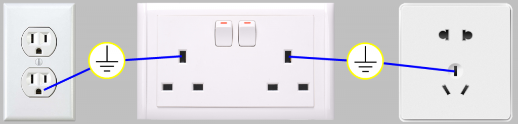
Figure 1. Location of Earth Ground on Common Electrical Receptacles
The power supply for most Pine Research potentiostats does not allow the earth ground connection to pass through to the instrument circuitry. As a result, there is no permanent, direct connection to the earth ground when the instrument is connected to the AC Mains (there is no connection to earth ground via the power cable plugged into a receptacle).
If necessary for a given experimental arrangement, a separate and deliberate connection to earth ground can be employed. Third-party grounding kits are available which provide a convenient connection to the earth ground found on most electrical receptacles (see Figure 2).
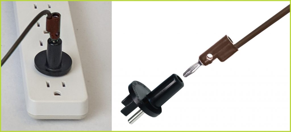
Figure 2. A Typical Earth Ground Connection Adapter with Banana Cable
In general, a connection to earth ground need only be made if it helps to reduce (or, at least, has no effect on) the amount of noise in the electrochemical signals being measured. In some laboratory environments and for certain types of experiments (e.g., AC methods), making a connection to earth ground may actually increase the amount of signal noise. Some trial-and-error experimentation may be necessary to decide whether or not to make a connection to earth ground.
1.2.2Chassis Terminal
 |
CHASSIS TERMINAL: |
| A metal case that surrounds and protects the electronic circuitry is called a chassis. A convenient connection point to this chassis is called a chassis terminal. |
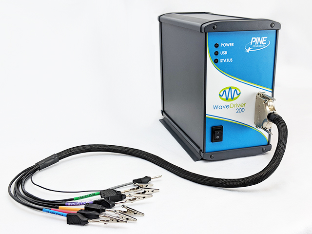
The metal case that contains a potentiostat circuitry is the instrument chassis. The chassis helps to protect the circuitry from environmental noise sources and ESD events. On a Pine Research WaveDriver model potentiostat,
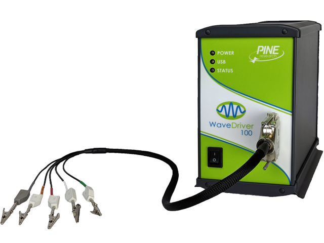 WaveDriver 100 EIS Potentiostat/Galvanostat
there are two convenient access points to the instrument chassis: the GRAY banana plug on the cell cable and a metal binding post on the back panel.
WaveDriver 100 EIS Potentiostat/Galvanostat
there are two convenient access points to the instrument chassis: the GRAY banana plug on the cell cable and a metal binding post on the back panel.
WaveDriver 100 EIS Potentiostat/Galvanostat
there are two convenient access points to the instrument chassis: the GRAY banana plug on the cell cable and a metal binding post on the back panel.The potentiostat cell cable has a mesh shield that is directly connected to the instrument chassis. This mesh shield effectively extends the instrument chassis along the length of the cell cable until the point where the mesh terminates and the individual cable lines emerge.
Some experiments require that the cell cable be extended beyond its usual length. Examples include routing a long cell cable through the side of a glovebox or using the additional cable associated with the Compact Voltammetry Cell Kit.
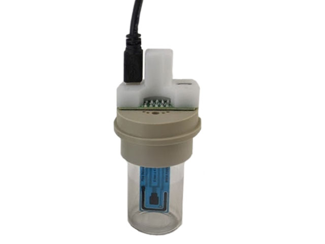 Screen-Printed Electrode Cell Starter Kit
When the cell cable is extended beyond its normal length, the protection afforded by the mesh should also be extended whenever possible. One way to do this is to wrap the additional lengths of cable in aluminum foil and then make a deliberate connection between the foil and the instrument chassis.
Screen-Printed Electrode Cell Starter Kit
When the cell cable is extended beyond its normal length, the protection afforded by the mesh should also be extended whenever possible. One way to do this is to wrap the additional lengths of cable in aluminum foil and then make a deliberate connection between the foil and the instrument chassis.When multiple measurement devices are used together in an experiment, it is common practice to connect the instrument chassis terminals for all of the instruments together. It is also common practice to place the electrochemical cell in a Faraday cage and connect the Faraday cage to the instrument chassis. These connections assure that the sensitive measurement circuitry in the various instruments and the electrochemical cell are all effectively sharing the same outer shield against environmental noise.
1.2.3DC Common
 |
DC COMMON: |
| In an analog circuit, the DC Common is the zero reference point against which signal voltages are measured. This point is also known as the analog ground, signal ground, or signal common. |
The DC Common for an instrument is the zero volt (0.0 V) reference point used by the waveform generation and signal measurement circuits. On a Pine Research WaveDriver model potentiostat,
WaveDriver 100 EIS Potentiostat/Galvanostat
there are two convenient access points to the DC Common: the BLACK binding post on the back panel of the instrument and the center pin of Rotator Control Port B also located on the back panel.
WaveDriver 100 EIS Potentiostat/Galvanostat
there are two convenient access points to the DC Common: the BLACK binding post on the back panel of the instrument and the center pin of Rotator Control Port B also located on the back panel.A potentiostat may send or receive analog signals to and from other electronic instruments, such as a waveform generator, an x – y recorder, a digital oscilloscope, an electrode rotator, a spectrometer, or a quartz crystal microbalance. These other instruments also have a DC Common line, which represents the common “zero volt” analog signal level. In general, the act of connecting a signal cable from the potentiostat to another instrument connects the DC Common lines for both instruments.
Many Pine Research potentiostats (specifically, WaveDriver
 WaveDriver 200 EIS Bipotentiostat/Galvanostat
models) offer separate connection points for DC Common and chassis terminal on the back panel. Certain instruments are shipped from the factory with a metal shorting bar that connects the DC Common to the chassis terminal, while others do not possess this feature. If present and desired, this shorting bar can be disconnected to allow the DC Common line to “float” with respect to the instrument chassis.
WaveDriver 200 EIS Bipotentiostat/Galvanostat
models) offer separate connection points for DC Common and chassis terminal on the back panel. Certain instruments are shipped from the factory with a metal shorting bar that connects the DC Common to the chassis terminal, while others do not possess this feature. If present and desired, this shorting bar can be disconnected to allow the DC Common line to “float” with respect to the instrument chassis.The act of deliberately floating or shorting the DC Common signal with respect to the instrument chassis may or may not reduce the amount of environmental noise picked up by the potentiostat. For any given experimental configuration, some trial-and-error experimentation may be required to determine the optimal configuration.
There are situations in which a floating DC Common is required. The most common cases are those in which one of the electrodes (usually the working or counter electrode) is part of a third-party apparatus (such as a quartz crystal microbalance or an electroplating system), and the third-party apparatus is known to make a direct connection between the electrode and the instrument chassis or earth ground. When an electrode is known to be grounded by a third-party apparatus, it is critical that all of the analog measurement signals in the potentiostat (including the DC Common) are floating with respect to the chassis and/or earth ground. Otherwise, an undesirable short circuit pathway between the electrode and DC Common is likely to occur via the third-party apparatus.
Finally, it is important to be aware of cases where a hidden connection indirectly compromises the floating DC Common. These cases can occur when multiple instruments and/or computers are interconnected with the potentiostat as part of a larger experimental configuration. One of the other instruments may make an internal connection between DC Common and the chassis or earth ground. Finding and eliminating such hidden connections often requires some detective work using an ohmmeter.
1.3Faraday Cages
When making sensitive electrochemical measurements (e.g., electroanalytical methods employing DC currents less than one microampere (< 1 µA) or small amplitude AC methods such as Electrochemical Impedance Spectroscopy), it is very important to place the entire electrochemical cell inside a metal Faraday cage to shield the experiment from environmental noise. In addition, the portion of the cell cable (near the electrochemical cell) where the individual signal lines emerge from the protective mesh should also be placed inside the Faraday cage.
After placing the ends of the cell cable and the electrochemical cell inside of the Faraday cage, a secure electrical connection should made between the metal Faraday cage and the potentiostat chassis terminal. This combination of the instrument chassis, the mesh around the cell cable, and the Faraday cage essentially puts the entire system (circuitry and cell) inside of an overall outer protective shield (i.e., the cell cable mesh and the Faraday cage act as an extension of the instrument chassis).
A Faraday cage can either be purchased directly from a supplier or fabricated using inexpensive and commonly-found materials. Anything from a commercial electrical enclosure to a cardboard box lined with aluminum foil can serve as a functional Faraday cage (see Figure 3). A Faraday cage requires an internal volume large enough to contain the entire electrochemical cell and all of the banana plugs at the end of the cell cable which connect to the various electrodes. Care should be taken to ensure that the electrode connections do not accidentally come into contact with the conductive walls of the Faraday cage.
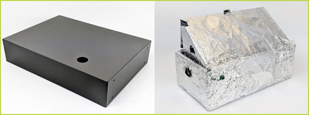
Figure 3. Common Examples of Faraday Cages
1.4Metal Apparatus
Electrochemical cells are often mounted using various metal apparatus (such as ring stands or laboratory clamps). These mounts, along with any other metal objects located near the electrochemical setup, can interfere with sensitive electrochemical measurements, especially if they are simply allowed to “float” rather than being electrically connected to a known point in the system. Some trial-and-error may be required to determine the best way to ground such metal objects, but in many cases, an alligator clip and a banana cable (see Figure 4) can be used to connect the metal object to the instrument chassis or to the earth ground or to both.
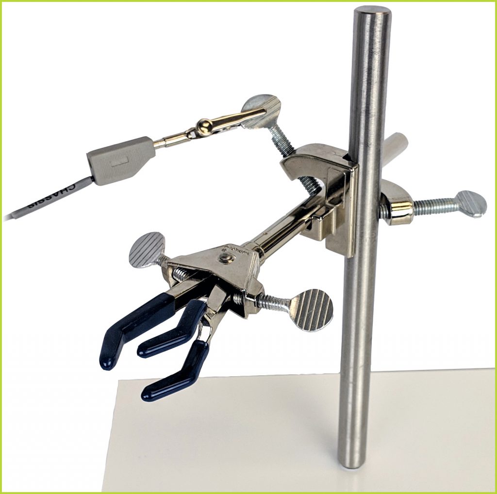
Figure 4. Metal Objects Near the Electrochemical Cell Should Be Grounded
1.5USB Isolation
It is important to note that a Pine Research potentiostat is designed to be connected to a personal computer (tower, desktop, or laptop) via a USB cable. It is generally undesirable for the chassis of the instrument to be connected to the chassis of the computer. To help isolate the instrument from the computer, the USB port (on the back panel) on most Pine Research potentiostats is mounted in a manner that helps prevent direct shorting between the instrument chassis and the computer chassis via the USB cable. Note that the USB shield line is capacitively coupled to the chassis of the instrument.
The communications lines within a USB cable carry digital signals and at least one line that is connected to the DC Common of the computer. To prevent interaction between the circuitry inside the computer and the sensitive measurement circuitry inside the instrument, Pine Research potentiostats have special circuitry that isolates the USB lines from the rest of the system. This prevents the DC Common of the computer from being connected to the DC Common of the instrument.