


Instrument User Guides
Back to Instrument User Guides Back to Applications Back to Knowledgebase HomeWaveNeuro Four FSCV Potentiostat User Guide
Last Updated: 5/7/19 by Neil Spinner
1Preface
1.1Scope
This User Guide describes the WaveNeuro 4 Multiple Channel Fast-Scan Cyclic Voltammetry Potentiostat System.
 WaveNeuro Two FSCV Potentiostat (Plus Bundle)
This guide is written for the scientist or engineer (student or professional) and assumes a basic knowledge of scientific measurement and data presentation. Portions of this manual are devoted to electrochemical concepts and assume some familiarity with the subject of electrochemistry.
WaveNeuro Two FSCV Potentiostat (Plus Bundle)
This guide is written for the scientist or engineer (student or professional) and assumes a basic knowledge of scientific measurement and data presentation. Portions of this manual are devoted to electrochemical concepts and assume some familiarity with the subject of electrochemistry.A small portion of this guide is dedicated to using the HDCV software package to control the WaveNeuro 4 instrument, primarily in the context of installing the instrument and verifying that it is working correctly. More extensive descriptions of how to use the HDCV software are provided in the additional documents listed below:
- HDCV User Guide (describes data acquisition software functions)
- HDCV Analysis User Guide (describes data analysis with HDCV data)
At the time of this user guide revision, both of the additional documents listed above can be obtained from The University of North Carolina at Chapel Hill Chemical Research Instrumentation Teaching and Core Labs (CRITCL) Electronics facility.
 UNC CRITCL Electronics Facility
1.2Copyright
This publication may not be reproduced or transmitted in any form, electronic or mechanical, including photocopying, recording, storing in an information retrieval system, or translating, in whole or in part, without the prior written consent of Pine Research Instrumentation.
1.3Trademarks
All trademarks are the property of their respective owners. NI®, NI-DAQ®, LabVIEW®, and DAQCard® are trademarks of National Instruments (Austin, TX). Windows® is a registered trademark of Microsoft Corporation (Redmond, WA). WaveNeuro® is a registered trademark of Pine Research Instrumentation (Durham, NC).
1.4Use Limitation
The WaveNeuro 4 instrument is not designed for use in experiments involving human subjects and/or the use of electrodes inside or on the surface of the human body.
Any use of this instrument other than its intended purpose is prohibited.
1.5Service and Warranty Information
For questions about the proper operation of the WaveNeuro 4 Fast-Scan Cyclic Voltammetry Potentiostat System or other technical issues, please use the contact information below to contact Pine Research directly.
 Contact
If the WaveNeuro 4 Fast-Scan Cyclic Voltammetry Potentiostat System or one of its components or accessories must be returned to the factory for service, please contact Technical Service (see above) to obtain a Return Material Authorization (RMA) form.
1.5.1Limited Warranty
The Pine WaveNeuro 4 Fast-Scan Cyclic Voltammetry Potentiostat System (Pine part number AF01FSCV4, hereafter referred to as “WARRANTED INSTRUMENT”) offered by Pine Research Instrumentation, Inc. (hereafter referred to as “SUPPLIER”) is warranted to be free from defects in material and workmanship for a one (1) year period from the date of shipment to the original purchaser (hereafter referred to as the "CUSTOMER") if used under normal laboratory conditions. SUPPLIER’s obligation under this warranty is limited to replacing or repairing parts which shall upon examination by SUPPLIER personnel disclose to SUPPLIER’s satisfaction to have been defective. The CUSTOMER may be obligated to assist SUPPLIER personnel in servicing the WARRANTED INSTRUMENT. SUPPLIER will provide remote support (via telephone or internet) to guide the CUSTOMER to diagnose and effect any needed repairs. In the event that remote support is unsuccessful in resolving the defect, SUPPLIER may recommend that the WARRANTED INSTRUMENT be returned to SUPPLIER for repair. This warranty is expressly in lieu of all other warranties, expressed or implied and all other liabilities. All specifications are subject to change without notice. The CUSTOMER is responsible for charges associated with non-warranted repairs, such charges including but not limited to travel expenses, tariffs, labor, parts and freight charges.
This warranty does not apply to headstage amplifiers, cables, or other accessories that are used in conjunction with the WARRANTED INSTRUMENT.
1.6Icons
Special icons (see Table 1) are used to call attention to safety warnings and other useful information found in this document.
| Icon | Meaning |
|
|
CAUTION: Indicates information needed to prevent injury or death to a person or to prevent damage to equipment. |
|
|
STOP: For a procedure involving user action or activity, this icon indicates a point in the procedure where the user must stop the procedure. |
|
|
NOTE: Important or supplemental information. |
|
|
TIP: Useful hint or advice. |
Table 1. Special Icons used in this User Guide
1.7End Panel Markings
The side/end panel of the WaveNeuro 4 bears information to identify the instrument (see Figure 1).
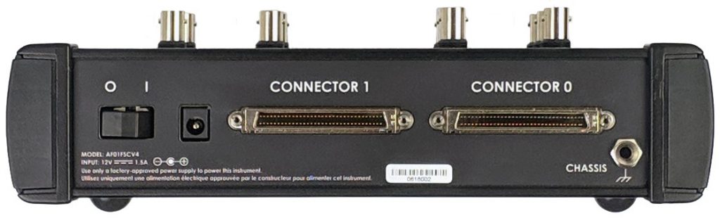
Figure 1. WaveNeuro Four End Panel
1.7.1Serial Number
For purposes of uniquely identifying a particular instrument, there is a label on the side/end panel of each WaveNeuro 4 which indicates the serial number. The serial number is also encoded with a machine-readable barcode on the same label (see Figure 1).
1.7.2Model Numbers
Pine Research part numbers for the WaveNeuro 4 instrument, power cords, and accessories are described in more detail later (see Section 2.5). WaveNeuro series of potentiostats have model numbers with the format AF01FSCV#, the # indicates the number of channels; therefore, the WaveNeuro 4 part number is AF01FSCV4.
1.8Safety Warnings
1.9Electrostatic Discharge Information
Electrostatic discharge (ESD) is the rapid discharge of static electricity to ground. An ESD event occurs when two bodies of different potential approach each other closely enough such that static charge rapidly passes from one object to the next. Sensitive electronics in the path of the discharge may suffer damage. Damaging ESD events most often arise between a statically charged human body and a sensitive electronic circuit. The human body can easily accumulate static charge from simple movement from one place to another (i.e., walking across a laboratory).
Potentiostat users must always be aware of the possibility of an ESD event and should employ good practices to minimize the chance of damaging the instrument. Some examples of good ESD prevention practices include the following:
- Self-ground your body before touching sensitive electronics or the electrodes. Self-grounding may be done by touching a grounded metal surface such as a water pipe.
- Wear a conductive wrist-strap connected to a good earth ground to prevent a charge from building up on your body.
- Wear a conductive foot/heel strap or conductive foot wear in conjunction with standing on a grounded conductive floor mat.
- Increase the relative humidity in the air to minimize static generation.
1.10Software Information
The Pine Research WaveNeuro 4 Fast-Scan Cyclic Voltammetry Potentiostat System utilizes a National Instruments Data Acquisition Device (NI PCIe-6363) to interface to a personal computer. The WaveNeuro 4 can be operated with High Definition Cyclic Voltammetry (HDCV). HDCV is a fast-scan cyclic voltammetry data collection and analysis program written by the research lab of R. Mark Wightman. HDCV was written in NI LabVIEW™ and requires LabVIEW Run-Time 2009™ or higher, NI-DAQ™ and NI-MAX™ to operate properly. NI-MAX™ software is required for accessing the National Instruments system and is provided with the data acquisition device. Academic users can obtain HDCV software from The University of North Carolina at Chapel Hill Chemical Research Instrumentation Teaching and Core Labs (CRITCL) Electronics facility.
UNC CRITCL Electronics Facility
2Instrument Information
2.1Background Subtracted Fast-Scan Cyclic Voltammetry Overview
Fast-scan cyclic voltammetry (FSCV) is an electrochemical technique that has been gaining popularity over the last few decades. FSCV makes analytical measurements in dynamic environments. With FSCV, a rapid potential ramp, typically >100 V/s, is continuously applied to a microelectrode. The application of this rapid potential ramp to the electrode generates large Faradaic current, due to electrochemical processes, and non-Faradaic current, mostly due to ion movement. The non-Faradaic current is stable over short periods of time (typically tens of seconds to a few minutes); therefore, current does not significantly change in short time periods. Faradaic current variation arising from changes in electroactive species concentration can be resolved by monitoring the difference in current over time. Typically, to visualize the changes in the concentration of electroactive species, one selects a single cyclic voltammogram (CV) and defines it as the background. During a defined collection time, the background CV is subtracted from experimental CVs. The resultant background-subtracted CV results in analytical data, which encodes changes in electroactive species as a function of time. CV peak positions provide clues as to the identity of the species measured, while the peak current magnitude corresponds to the change in concentration of the species.
A series of background subtracted CVs collected over a period of time can be visualized as an electrochemical color plot. The color plot is a graphical representation of a series of CVs, with voltage plotted on the y-axis, time plotted on the x-axis, and faux-color representing the current magnitude. The color plot enables large numbers of background subtracted CVs to be analyzed and changes in the concentration of electroactive species to be quickly identified (see: Figure 2).
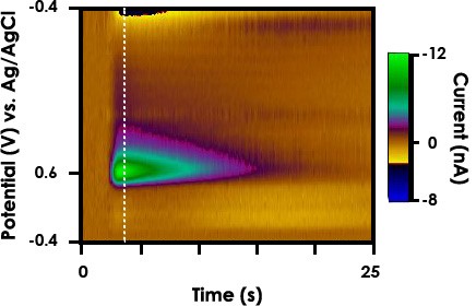
Figure 2. FSCV Color Plot of Evoked Dopamine Release in a Freely Moving Rat
FSCV monitors rapid fluctuations in the concentrations of electroactive species, such as electroactive neuromodulators, in small volumes of solution with very good limits of detection. As the technique has evolved, there are now protocols to maximize responsivity and selectivity to monitor changes in the extracellular concentration of electroactive neurotransmitters, such as catecholamines, in functioning tissue and even behaving animals.
The typical data representation for FSCV is a color plot, which is a stack of many CVs in time (see Figure 2). Viewing CV data as a color plot highlights differential electrochemical behavior, such as for the release of dopamine in the dorsal striatum of a rat (see Figure 2). Studies utilizing FSCV have led to new insights in neuroscience. FSCV is quickly becoming an established technique in neuroscience for monitoring extracellular changes in concentration of electroactive biomolecules, such as catecholamines.
2.2Instrument Description
The WaveNeuro 4 Fast-Scan Cyclic Voltammetry System is a benchtop potentiostat specially designed for FSCV measurements. The WaveNeuro 4 connects to a personal computer via a National Instruments data acquisition card and is controlled by a third party software, such as High Definition Cyclic Voltammetry (HDCV) software. The WaveNeuro 4 controls up to four independent two-electrode electrochemical cells or enables up to four working electrodes to be controlled in a single system. The electrochemical accessories that connect to the WaveNeuro 4 are working electrodes, typically a carbon fiber microelectrodes, and a reference electrode often Ag/AgCl (see Section 2.7.7 for more details about electrode connections).
The WaveNeuro 4 applies a potential waveform that is controlled by the software. Note that the WaveNeuro 4 is designed to apply the electrochemical waveform to the working electrodes and maintain the reference electrode at ground (see Section 3). Such an arrangement is called a "Working Driven" system, as compared to a "Reference Driven" system. More on this topic in a dedicated knowledgebase article. This configuration enables independent waveforms to be applied to each of the working electrodes. Some limitation exist on the software’s handling of four working electrodes. See Section 6 of this user guide to review software settings on the application of multiple waveforms in HDCV.
To facilitate multiple working electrodes in a single electrochemical environment, the potential ramp is applied to the working electrode while the differential current is also measured at the working electrode. The measured current range is defined by the gain of the electrochemical headstage. The standard Pine Research headstage provides a current range of ±2,000 nA (5 MΩ or 200 nA/V). Additional headstage amplifier gains and configurations are available from Pine Research.
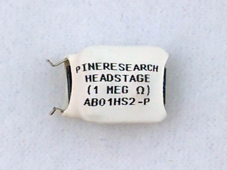 FSCV Headstage Amplifier (1 megaohm/1,000 nA/V)
Please contact us
Contact
with any special requests/custom gain levels.
FSCV Headstage Amplifier (1 megaohm/1,000 nA/V)
Please contact us
Contact
with any special requests/custom gain levels.
FSCV Headstage Amplifier (1 megaohm/1,000 nA/V)
Please contact us
2.3Software Description
The WaveNeuro 4 Fast-Scan Cyclic Voltammetry Potentiostat system has been designed for use with third party data collection and analysis software. Specifically, our engineers have targeted the use of High Definition Cyclic Voltammetry (HDCV) and HDCV Analysis.
The HDCV software was written the R. Mark Wightman Research Group at the University of North Carolina at Chapel Hill. The HDCV scientific software is a LabVIEW based application which interfaces the WaveNeuro 4 to a National Instruments interface board. HDCV performs complex electrochemical measurements and analysis.
Academic users can obtain HDCV software from The University of North Carolina at Chapel Hill Chemical Research Instrumentation Teaching and Core Labs (CRITCL) Electronics facility.
UNC CRITCL Electronics Facility
2.4Instrument Specifications
The WaveNeuro 4 Fast-Scan Cyclic Voltammetry Potentiostat System offers a complete solution to perform fast-scan cyclic voltammetry.
Complete specifications for the WaveNeuro Four can be found in the Product Specifications section of the Knowledgebse.
Product Specifications
You can also compare FSCV potentiostat systems in the Product Specifications section of the Knowledgebase.
FSCV Systems
2.5Major System Components
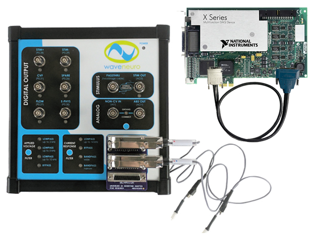
A WaveNeuro 4 Fast-Scan Cyclic Voltammetry Potentiostat System, as shipped from the production facility, includes the parts listed in the following table (see Table 2). The individual part numbers associated with these parts is also provided. An image representation of the included components is provided (see Figure 2).
| Part Number | Description |
| AF01FSCV4 | WaveNeuro 4 Fast-Scan Cyclic Voltammetry Potentiostat System |
| RRCH0124-T or RRCH0136-T | Four headstage amplifier cable, DB-25 connector, 24” or 36” |
| AC01HS1 | Four FSCV headstage amplifier, 200 nA/V (5 MΩ) or 1,000 nA/V (1 MΩ) working driven |
| AC01HC0315-5 or AC01HC0325-5 | 1.5" or 2.5" Microelectrode-headstage couplers (packages of 5) |
| RRPA12V | AC Adapter/Power Supply; 12 V, 2.5 A input |
| AFDUM4 | WaveNeuro dummy cell |
Table 2. WaveNeuro 4 System Components
Additionally, the WaveNeuro 4 will ship with a power cord for use with the AC Adapter. The cord will have the plug-style suitable for the country of use. Power cords are rated for 10 A and are designed to mate with the standard C13 type connector on the power supply.
A National Instruments interface board and interface cables will be required to control the WaveNeuro 4 under software control. These may be obtained from Pine Research or users may obtain them separately, directly from National Instruments (see Table 3). A PC with an open PCIe slot on the motherboard is not supplied by Pine Research and must be present for operation as well.
| Part Number | Description |
| EANPCIE6363 | National Instruments PCIe-6363 Interface Board |
| EWCP6102 | National Instruments SHC68-68 Interface Cables x2 |
Table 3. Additional WaveNeuro 4 System Components (Sold Separately)
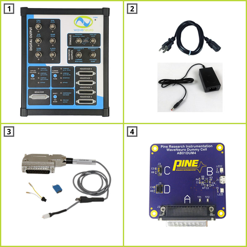
| Image # | Name | Description |
| 1 | WaveNeuro 4 System | WaveNeuro 4 Fast-Scan Cyclic Voltammetry Potentiostat System |
| 2 | Power Supply and Power Cord | 12 VDC (2.5 A) power supply; 100 to 240 VAC (50/60 Hz); C13 Connector |
| 3 | Headstage Amplifier Kit | Cable with DB-25 connector, headstage amplifier, microelectrode connectors (four sets included) |
| 4 | WaveNeuro Dummy Cell | Network of known resistors and capacitors used to test WaveNeuro 4 and ensure system in proper operation/configuration |
Figure 3. Major WaveNeuro 4 System Components (not to scale)
2.6WaveNeuro 4 Side/End Panel
The side/end panel of the WaveNeuro 4 features several input and output connections whose location and function is described below (see Figure 4).
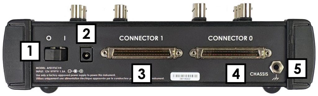
| Image # | Name | Description |
| 1 | Power Switch | Switch to turn the main power on/off |
| 2 | Power Input | A low voltage direct current (12.0 VDC (±5%), 1.0 A) power input connector. Please use power supply included with original shipment for best performance |
| 3 | Connector 0 | National Instruments type-connector to connect to the National Instruments data acquisition card in the computer (68-Pin Connector) |
| 4 | Connector 1 | National Instruments type-connector to connect to the National Instruments data acquisition device in the computer (68-Pin Connector) |
| 5 | Chassis Terminal | The chassis terminal is a banana binding post (back panel) which may optionally be used to connect the chassis to earth ground to improve noise screening (shielding) |
Figure 4. Description of the WaveNeuro 4 Side/End Panel
2.7WaveNeuro Four Top Panel
The top panel of the WaveNeuro 4 has BNC connectors, filter selection hardware, electrochemical headstage cable connector, behavioral input connector (digital inputs), and LED indicators (see Figure 5).
2.7.1WaveNeuro Four Connectors
The top panel of the WaveNeuro 4 is organized by the function of the connectors and buttons. The BNC connections are categorized as DIGITAL OUTPUT, STIMULUS, and ANALOG connectors. A fuller description of the connectors in each category is described below. Other categories of connector and buttons on the front panel include HEADSTAGE and BEHAVIOR, which are male DB-25 connectors that accept headstage and behavioral inputs. Lastly are the APPLIED VOLTAGE and CURRENT RESPONSE filter selections. Filter selections for current or voltage are made by pressing a button on the top panel (see: Figure 5).
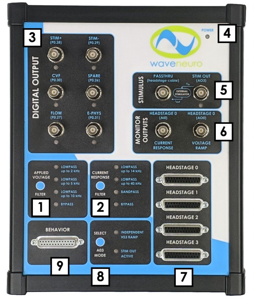
| Image # | Name | Description |
| 1 | Voltage Filter Selection | Push button selection to filter applied voltage signal. Green LED light indicates which setting is engaged (see Section 2.7.3) |
| 2 | Current Filter Selection | Push button selection to filter measured current signal. Green LED light indicates which setting is engaged (see Section 2.7.3) |
| 3 | Digital Output Connectors | Female BNC Connectors, NI Interface Board address location listed in parentheses (e.g. P0.27), below name for connector, which corresponds to HDCV software naming conventions (see Section 2.7.4) |
| 4 | Power Indicator | Blue LED power indicator |
| 5 | Stimulus Connectors | Female BNC connectors for stimulus functions (see: Section 2.7.5) |
| 6 | Monitor Outputs | Two female BNC connectors providing analog output monitoring of applied voltage (ramp) and measured current (signal) (see Section 2.7.6) |
| 7 | Headstage Input Connectors | Female DB-25 Connectors for Headstage input signals (see Section 2.7.7) |
| 8 | Analog Out 3 Mode Selector | Push button selection to choose whether to use line AO3 for an independent FSCV waveform on Headstage 3 (Independent HS3 Ramp) or instead to disable Headstage 3 and use Stimulus options (Stim Out Active). (see Section 2.7.8). |
| 9 | Behavioral Input Connectors | Female DB-25 Connectors for behavioral input signals (see Section 2.7.7) |
Figure 5. Top Panel of the WaveNeuro Four
2.7.2WaveNeuro Four LED Indicators
The LED lights indicate power, digital trigger activation, and filter selection. The primary purpose of the LEDs is to indicate the state of the instrument and whether or not the instrument has power. The various LED indicators are described in more detail below (see Table 4).
| LED | LED Color/State | Indication |
| Power
|
 not illuminated not illuminated |
When the power LED is off, the WaveNeuro 4 power switch is in the off position (or the power supply is not providing power). |
 solid blue solid blue |
When the power LED is solid blue, the power supply is providing power to the WaveNeuro 4 and the power switch is in the on position. | |
| Filter Select |  solid green solid green |
The selected filter LED will be illuminated a solid green. Push button next to the LED bank changes selected filters. |
| Triggers | blinking green |
The application of a waveform will cause the CVF LED to blinking. Blinking is indicative of the number of waveforms being applied per second. |
| solid green |
While a trigger line is activate (high) this LED will be illuminated. |
Table 4. Description of the WaveNeuro 4 Side/End Panel
2.7.3WaveNeuro Four Filter Settings
The WaveNeuro 4 has selectable filters on the waveform output and on the measured current. The WaveNeuro 4 applies the same waveform filter to all four channels, whether or not the ramp (waveform) is the same or different. In other words, the Applied Voltage Filter applies the highlighted filter to all four waveform channels and the Current Response Filter applies the selected filter to all four current channels. The waveform filter can be set by pressing the button beside the filter options and LEDs (see Figure 5). The current response filter can be set by pressing the button beside the current response filter options and LEDs (see Figure 5). In both cases, the LED light next to the filter options is illuminated when selected. The default settings for applied waveform is LOWPASS up to 2 kHz and for the current response filter is LOWPASS up to 14 kHz.
2.7.4Digital Triggers
The six BNC connectors in the DIGITAL OUTPUT section (see Figure 5) are digital (TTL) triggers that can be programed to activate external hardware. Such programming occurs in the software connected to the WaveNeuro 4, via the Interface board, on the PC. The most commonly used trigger application is driving a solenoid for operating the instrument with a flow cell.
2.7.5Stimulus Connectors
The WaveNeuro 4 is equipped with an analog output and PASSTHRU BNC connectors (see Figure 5). The STIM OUT (AO3) BNC is mapped to the NI Interface board and outputs an analog voltage signal for stimulation. This output signal feeds to a third-party voltage to current converter device (such as a NeuroLog®, not available from Pine Research), which then outputs a stimulating current. By making a connection between the voltage to current converter device and the PASSTHRU BNC connector on the WaveNeuro 4, the stimulating current feeds directly to the integrated stimulator connectors on the headstage cable. The current is independent of the WaveNeuro 4 circuitry in this configuration. Note that to use STIM, STIM should be specified in both the hardware and the software settings (See: Section 5.1.3).
2.7.6Monitor Outputs
On the top panel in the section labeled MONITOR OUTPUTS, there are two female BNC connectors, labeled as HEADSTAGE 0 CURRENT RESPONSE (AI0) and HEADSTAGE 0 VOLTAGE RAMP (AO0) (see Figure 5). These connectors offer a method to externally monitor the voltage output (ramp, from the NI board) on Headstage 0 and/or to monitor the current input from Headstage 0. Both connections are passive monitoring connections only.
2.7.7Headstage Connectors
Four DB-25 HEADSTAGE connectors (see Figure 5) are intended for use with four Pine Research headstage cable kits. With four headstage cable kits up to four different working electrodes can be used. The headstage cable kits are included with the initial WaveNeuro 4 shipment (see Figure 3). Headstage amplifiers connect directly to the cable and are interchangeable. The microelectrode-headstage couplers connect to the headstage amplifier. Replacements of the headstage cable kit components are available from Pine Research. Additional information on the headstage cable and its connections are provided in Section 3.
2.7.8Analog Out 3 Mode Selector
The WaveNeuro 4 offers up to four independent FSCV channels, a features that comes with one limitation. In four-channel mode, all analog outputs on the NI PCIe-6363 interface board will be used, which means that the WaveNeuro 4 Stimulus output (STIM OUT AO3) is not available as it will be used for an FSCV waveform. In this setup, the “INDEPENDENT HS3 RAMP” LED must be illuminated.
Alternatively, The WaveNeuro 4 can be setup to perform three independent FSCV channels and a stimulus output, which means that the WaveNeuro 4 fourth channel (HEADSTAGE 3), which is also tied to AO3, is not available. In this setup, the “STIM OUT ACTIVE” LED must be illuminated. Change the mode as desired by pressing the “SELECT AO3 MODE” button (see Figure 5).
2.7.9Behavioral Connectors
The DB-25 BEHAVIOR connector (see Figure 5) has been configured as a series of digital (TTL) inputs lines that enable up to fifteen digital input signals. The digital input signals can be displayed by software. For example, the WaveNeuro 4 was tested using a SuperPort™ from Med Associates, Inc. as the behavioral hardware and HDCV as the software for displaying the results. Using this combination, events can be time locked with electrochemical changes observed in the color plots.
3Included Accessories
3.1Headstage Amplifier kit
The Pine Research Instrumentation electrochemical headstage amplifier is a high gain current to voltage converter for use with microelectrode systems. This electrochemical headstage is specifically designed for use in a two-electrode system using Fast-Scan Cyclic Voltammetry as the electrochemical technique (see Figure 6).
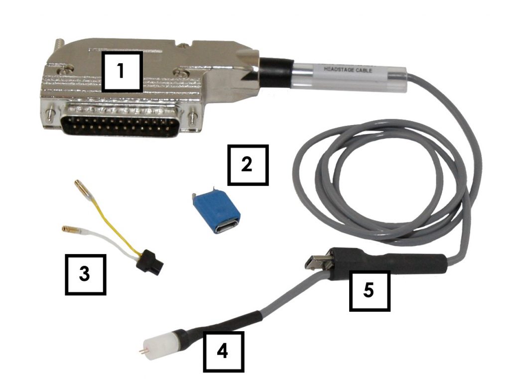
| Image # | Name | Description |
| 1 | Headstage Cable | Male DB-25 Connector, connects to WaveNeuro 4 HEADSTAGE Connector. Pinout available (see Figure 7). Available lengths: 24” and 36” |
| 2 | Headstage Amplifier | High gain current to voltage converter for use with two microelectrode system. Working driven. Standard gains of 200 nA/V (5 MΩ) or 1,000 nA/V (1 MΩ). Other custom gain amplifiers may be available |
| 3 | Microelectrode-Headstage Coupler Wires | Wires to connect microelectrodes to headstage. Yellow = working electrode, White = reference electrode. Available in packages of 5 with lengths of 1.5” or 2.5”. Custom length wires may be available |
| 4 | Integrated Stimulation Connector | Two-prong 305-CP type plug for delivering stimulating current |
| 5 | Headstage Amplifier Connector | Male connector onto which the Pine Research headstage amplifiers are mounted. |
Figure 6. Standard WaveNeuro Headstage Cable Kit Labeled
3.1.1Working Driven Headstage Description
Pine Research currently offers working driven headstage amplifiers. In a working driven system, the reference electrode is grounded. The FSCV potential waveform (ramp) is connected to the non-inverting input of the operational amplifier, while the working electrode is connected to the inverting input. In this arrangement, the voltage at the microelectrode will follow the ramp applied to the inverting input.
 Takmakov, P.; McKinney, C. J.; Carelli, R. M.; Wightman, R. M. Instrumentation for fast-scan cyclic voltammetry combined with electrophysiology for behavioral experiments in freely moving animals. Rev. Sci. Instrum., 2011, 82(7), 074302.
This configuration enables the application of independent waveforms to each working electrode.
Takmakov, P.; McKinney, C. J.; Carelli, R. M.; Wightman, R. M. Instrumentation for fast-scan cyclic voltammetry combined with electrophysiology for behavioral experiments in freely moving animals. Rev. Sci. Instrum., 2011, 82(7), 074302.
This configuration enables the application of independent waveforms to each working electrode.
In the working-driven configuration, current arising from electron-transfer reactions, such as the oxidation of dopamine, passes between reference and working electrodes. The measured current passes through the headstage amplifier, where it is converted to voltage, and sums with the ramp voltage at the inverting input. Simple mathematical rearrangement and use of Ohm’s law describes a working driven headstage amplifier (see Equation 1).
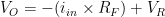 |
(1) |
where  is the output voltage,
  is input current,
  is feedback resistor (gain), and
  is the CV ramp voltage. By rearrangement, the signal voltage (proportional to the current across the 5 MΩ feedback resistor in the 200 nA/V headstage) is then
is the output voltage, is input current, is feedback resistor (gain), and is the CV ramp voltage. By rearrangement, the signal voltage (proportional to the current across the 5 MΩ feedback resistor in the 200 nA/V headstage) is then |
(2) |
HDCV software, which supports the WaveNeuro 4 FSCV Potentiostat system, performs software subtraction of the ramp according to this relationship, resulting in only the true differential current measurement.
Takmakov, P.; McKinney, C. J.; Carelli, R. M.; Wightman, R. M. Instrumentation for fast-scan cyclic voltammetry combined with electrophysiology for behavioral experiments in freely moving animals. Rev. Sci. Instrum., 2011, 82(7), 074302.
While Pine Research does not offer them, the FSCV community has traditionally used reference driven headstages. In this configuration, the working electrode is virtually grounded. The FSCV potential waveform (ramp) is connected to the inverting input of the operational amplifier, while the working electrode is connected to the non-inverting input. In this arrangement, the voltage at the microelectrode is independent of the ramp applied to the non-inverting input. More details on the differences are provided within the knowledgebase.
Working-Driven vs. Reference-Driven Systems for FSCV
The differential response at a working-driven or reference-driven headstage are equivalent, as illustrated below (see Figure 7). As explained above, a working driven system sums the CV waveform with the signal. Subtracting the CV waveform from the measured response yields the differential signal, which is equivalent to a reference driven system, whose response was not superimposed on the CV waveform (see Figure 7).
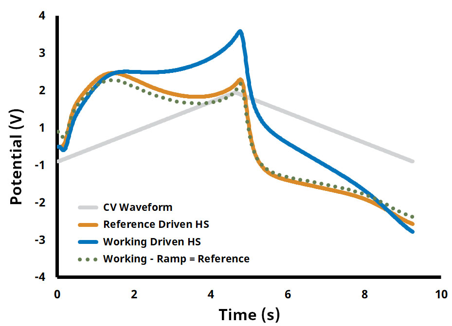
Figure 7. Working Driven vs. Reference Driven Headstage Response Comparison
3.1.2Headstage Cable Kit Detailed Description
The headstage is comprised of three components 1) headstage cable with male DB-25 connector; 2) headstage amplifier; and 3) microelectrode-headstage couplers (see Figure 6). The connector pinout for the headstage DB-25 connector provides the user with detailed information about the pin configuration (see Figure 8).
The cable has an integrated stimulator line that terminates in a 305-CP plug. The headstage amplifier module provides the amplification of the measured electrochemical signal. The module has two connectors, one for the headstage cable and one for the electrode connection wires. The connection wires are used to connect the amplifier to the working (yellow) and reference (white) electrodes.
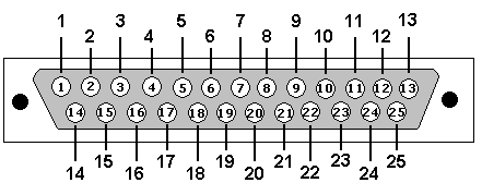
| Pin # | Signal |
| 5 | Power In +15 V |
| 6 | I/E Output |
| 7 | Ground |
| 9 | Power In -15 V |
| 12 | Stim Connection |
| 14 | Ramp In |
Figure 8. Headstage Cable DB-25 Connector Pinout Diagram
3.2WaveNeuro Dummy Cell Description
A dummy cell is a network of known resistors and capacitors that can be used to test a potentiostat to ensure that the instrument is working properly. The dummy cell included with the WaveNeuro 4 also provides for an easy way to diagnose headstage and cable concerns.
The WaveNeuro Dummy Cell (part number: AFDUM4) is included with the initial purchase of a system. The WaveNeuro Dummy Cell has four separate connections to enable testing of the potentiostat and cabling (see Figure 9). Description of how to utilize this dummy cell to verify the performance of the WaveNeuro 4 and to check environmental noise is provided in Section 4. Upon initial setup of a system the dummy cell should be used to evaluate if any environmental noise is entering into the measurement system. The dummy cell is also used for troubleshooting and isolating issues with the potentiostat and headstage cable components. Please store the WaveNeuro Dummy Cell in a safe place for future use.
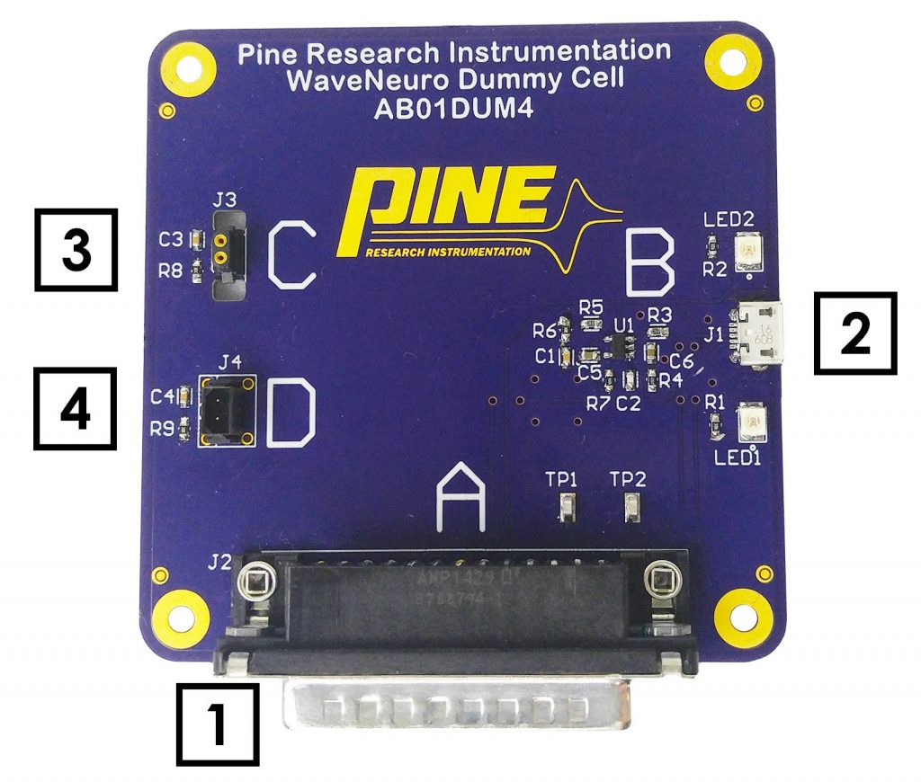
| Image # | Name | Description |
| 1 | Male DB-25 Connector | A connects to HEADSTAGE inputs on WaveNeuro 4. This configuration can be used for direct testing of the WaveNeuro 4 |
| 2 | Headstage Connector Test Site | B connects to the headstage connector on the cable, for evaluating the cable up to the headstage connector |
| 3 | Amplifier | C connects directly to a headstage amplifier, to independently test the function of the amplifier circuit |
| 4 | Microelectrode-Headstage Coupler Wire Test Site | D connect to each coupler wire to test the function of the coupler independently |
Figure 9. WaveNeuro Dummy Cell Connections
4System Installation
Setting up the WaveNeuro 4 system in a laboratory consists of three basic steps: 1) software and data acquisition system installation; 2) physical installation of the WaveNeuro 4; and 3) system testing. The installation process typically requires 60 minutes.
For illustrative purposes, this User Guide will describe the installation of WaveNeuro 4 Fast-Scan Cyclic Voltammetry Potentiostat System under control of High Definition Cyclic Voltammetry (HDCV) software (see Section 1.10). There are other software programs, such as WCCV®, Demon®, and TarHeel CV®, which may be compatible; however, Pine Research cannot provide software support for these programs and are limited in our ability to assist with software-hardware-interface board communication.
4.1Data Acquisition Interface Installation
After obtaining a software application (see: Section 1.10) proceed with the following installation. The data acquisition software for the interface board are included with the purchase of a National Instruments interface board. For both software, ensure the computer used in conjunction with this system meets minimum specifications (see Table 5).
| Processor Class | Intel Pentium IV or equivalent/compatible |
| Processor Speed | 1 GHz minimum recommended |
| Physical Memory | 1 GB (32-bit OS); 2 GB (64-bit OS) minimum |
| Screen Resolution | 1024 x 768 pixels or greater required |
| Operating System | Windows XP (32 bit), 32 or 64 bit Windows 7, 8, 10 |
| Data Acquisition | NI PCIe-6363 |
| Prerequisite Software | NI Max, LabVIEW Run-Time 2009 or higher |
Table 5. Recommended Minimum PC Specifications
Note that the prerequisite software (NI MAX and Labview Run-Time 2009 or higher) are provided with the purchase of the National Instruments PCIe-6363 interface board. In the event that they are missing from the computer, these components are available for free download from the National Instruments website.
National Instruments Drivers
4.1.1Installation of National Instruments Software
NI-DAQ™mx software is supplied with the National Instruments (NI) PCIe-6363 data acquisition card. A standard installation of the NI-DAQ™mx software is demonstrated through a series of screenshots shown below. The screenshots were obtained for NI-DAQ™mx 14.0 installed from the DVD supplied with a NI PCIe-6363.
- Insert the DVD, supplied by NI, into the computer (or download and install the driver as instructed). A dialog window appears on the computer screen. Select and Run autorun.exe. If this window does not appear on the screen then open Windows Explorer, navigate to the DVD, and select autorun.exe from the file directory.
- After the installer begins to run, a dialog window with installation options will appear. Select Install NI-DAQmx from the list.
- On the next dialog window that appears, specify the destination directory and click Next. Typically, the default location is a good choice, but you can specify a location if desired (click Browse and navigate to the desired location).
- On the next dialog window, that appears, choose Typical Installation.
- The next dialog window will prompt for automatic updates. Users can make a choice by ticking or un-ticking the box and pressing Next. Then, on the next dialog window, review the National Instruments Software License Agreement. Select the I accept… radio button and press Next.
- The next dialog window will itemize a list of changes during the installation. Press Next to continue.
- After the progress bar dialog completes, the installer will suggest restarting the PC. After restart, the installation of NI-DAQTMmx is complete.
4.1.2Installation of the PCIe-6363 Data Acquisition Interface Board
Ensure that the motherboard of the target PC has an open PCIe slot. Walk through the following steps to physically install the PCIe-6363.
- Unplug the personal computer and open the computer case.
- On the computer mother board find a PCI express expansion slot. Mother boards typically have several expansion slots. An example of an open PCIe slot has been provided (see Figure 10). Refer to mother board documentation for assistance in finding the PCI express slot, if needed.
- Ground yourself by touching the computer case and remaining in contact with the case during the installation.
- Install the card into the empty PCI express slot and secure it, then close the computer and power it on.
- After starting the computer run National Instruments NI MAX (Measurements and Automation Explorer) application. The application icon/link will be in the destination folder specified during installation of the software.
- Under My System on the left hand side menu - select Devices and Interfaces.
- NI PCIe-6363 should be listed under Devices and Interfaces with a default name Dev0. If the PCIe-6363 is not named Dev0, select the interface board on the left side of the application. On the right side, the name field appears. Change the name to 0, if not already named Dev0.
- Use the NI MAX software to interact with the PCIe-6363. You may click self-test or calibrate buttons at the top. If physical installation of the board is successful, you are finished. If not, repeat steps 1 - 8, ensuring that the board seats securely and completely into the PCI express slot. There are often screws/connectors that keep expansion boards in place.
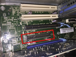
Figure 10. PCIe Slot (Red Rectangle) on a PC Motherboard
4.1.3Verify Installation of Data Acquisition Interface Board
Launch the NI MAX software installed on the computer (see: Section 4.1.1). NI MAX enables the user to check the install National Instruments software and hardware. To check the installation of the PCIe-6363, select Devices and Interfaces, complete the following steps:
- From Devices and Interfaces section, select the NI PCIe-6363.
- A series of settings will appear on the right side of the application. Verify that the PCIe-6363 is named Dev0, highlighted (see Figure 11).
- Run a self-test of the PCIe-6363 to ensure it is installed properly by clicking the self-test button at the top of the application window. A dialog window will alert you of the outcome of the self-test.
- Verify the software version by clicking on the software section on the left side of the application window.
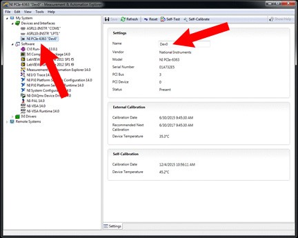
Figure 12. NI MAX Software Setting Device Name
4.2Software (HDCV) Installation
The WaveNeuro 4 is designed to run on third-party data acquisition software applications, such as HDCV. Review previous information about obtaining software (see Section 1.10). To install HDCV follow these steps:
- Select and run the setup application file provided. After starting the file a series of dialog boxes will appear. First, select a directory for HDCV (see Figure 12).
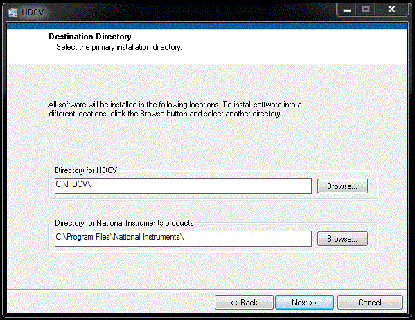
Figure 12. HDCV Software Setup Screen - Screen 1
- As with NI-DAQTMmx, review and accept the license, the installation summary, watch the installation progress, and after complete, restart the computer.
- After installation of the National Instruments software, the PCIe-6363 data acquisition device, and HDCV software, the HDCV software should be operational. Open the installation file folder for HDCV and select the HDCV application. HDCV can be started by double-clicking on the application. After a few seconds, HDCV should appear on the monitor (see Figure 13). If HDCV does not start please refer to troubleshooting or contact Pine Research Instrumentation.
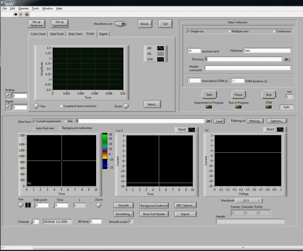
Figure 13. HDCV Application upon First Startup