


WaveDriver Bipotentiostat Cell Cable
Last Updated: 5/22/19 by Neil Spinner
1WaveDriver Bipotentiostat Cell Cable
The WaveDriver Bipotentiostat Cell Cable (Pine Research part number ACP3E01)
 WaveDriver Bipotentiostat Cell Cable
is used with the WaveDriver 200
WaveDriver Bipotentiostat Cell Cable
is used with the WaveDriver 200
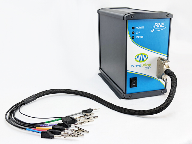 WaveDriver 200 EIS Bipotentiostat/Galvanostat
and WaveDriver 40
WaveDriver 200 EIS Bipotentiostat/Galvanostat
and WaveDriver 40
 WaveDriver 40 DC Bipotentiostat/Galvanostat
models.
WaveDriver 40 DC Bipotentiostat/Galvanostat
models.
WaveDriver Bipotentiostat Cell Cable
is used with the WaveDriver 200
WaveDriver 200 EIS Bipotentiostat/Galvanostat
and WaveDriver 40
WaveDriver 40 DC Bipotentiostat/Galvanostat
models.Using this cell cable, connections can be made to simple two-terminal cells (such as batteries, fuel cells, solar cells, amperometry sensors, capacitors, resistors, and inductors), traditional three-electrode voltammetry cells (including those which contain a rotating disk electrode or a rotating cylinder electrode), compact voltammetry cells, and to more complex dual working electrode cells (including rotating ring-disk electrode cells).
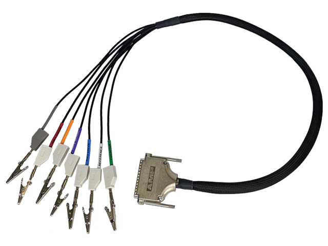
1.1Color Description
The WaveDriver Bipotentiostat Cell Cable breaks out the instrument cell port connections to six shielded coaxial lines and one unshielded line (the GRAY instrument chassis line). The shielded coaxial lines terminate in banana plugs that are designed to be stacked as needed and directly connected to electrodes. Alligator clips that slide onto the banana plugs are included. A tabular summary of the color code for these lines is provided (see Table 1).
| Color | Description | ID | Type | |
| WHITE | Reference Electrode | REF | Sense | |
| GREEN | Counter Electrode | CTR | Drive | |
| GRAY | Instrument Chassis | Ground | ||
| RED | Primary Working Electrode (K1) | WK1 | Drive | |
| ORANGE | Primary Working Electrode (K1) | Sense | ||
| BLUE | Secondary Working Electrode (K2) | WK2 | Drive | |
| VIOLET | Secondary Working Electrode (K2) | Sense | ||
Table 1. WaveDriver Bipotentiostat Cell Cable Color Description
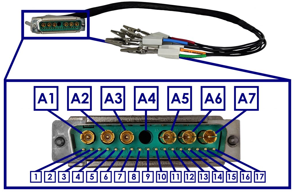
1.2Cable Pinout
NOTE: The high input impedance SENSE lines carry only very small currents during normal operation. Each of these SENSE lines is terminated with a resistor embedded within the banana plug at the end of the cable.
 |
|||
| Pin | Signal | Pin | Signal |
| A1 | Counter (CTR) | 6 | DC Common |
| A2 | Working Sense 2 (K2) - includes terminating resistor | 7 | Cable Identification |
| A3 | Working Drive 2 (K2) | 8 | |
| A4 | Unused | 9 | |
| A5 | Reference Sense (REF) - includes terminating resistor | 10 | |
| A6 | Working Drive 1 (K1) | 11 | Unused |
| A7 | Working Sense 1 (K1) - includes terminating resistor | 12 | |
| 1 | Analog Ground | 13 | |
| 2 | Unused | 14 | |
| 3 | Chassis Connection | 15 | |
| 4 | 16 | ||
| 5 | Unused | 17 | |
Figure 1. WaveDriver Bipotentiostat Cell Port and Cell Cable Pinout