


Automated Control of Electrode Rotators
Last Updated: 5/30/19 by Neil Spinner
1Overview
It is often convenient for the rotation rate to be controlled via an externally supplied signal. Many potentiostats are capable of providing such a signal to control the rotation rate while simultaneously performing electrochemical measurements. An externally supplied signal is also required when performing hydrodynamically modulated voltammetry, where the rotation rate is varied sinusoidally as electrochemical measurements are made with the potentiostat. All modern Pine Research potentiostats can be used to control modern rotators (rate, start, and stop).
The principle behind automation is the same for any potentiostat and rotator combination. Via software, a potentiostat is configured to send an analog voltage, proportional to a rotation rate, out from an accessory output (not cell cable), to the external control input on the rotator. The rotation rate changes as a function of the input voltage, and the voltage to rotation rate conversion setting (see Table 1). If you are using a Pine Research rotator with a potentiostat from a different manufacturer, consult that manufacturer to determine the appropriate input ratio to use.
| Input Ratio |
| 1 RPM/mV |
| 2 RPM/mV |
| 4 RPM/mV |
Table 1. Rotation Rate Control Input Ratios
The default setting in Pine Research AfterMath Software is 1 RPM/mV. Since electrode rotators can be used with other potentiostat brands, consult with your brand representative to learn the expected rotation rate input ratio their software uses. Some software may allow you to specify this ratio. The input ratio can be changed fairly easily for both the MSR
 Changing Input Rotation Rate on MSR Rotator
and WaveVortex 10.
Changing Input Rotation Rate on MSR Rotator
and WaveVortex 10.
2AfterMath Control of Electrode Rotation
In AfterMath, there are rotating electrode experiments and these methods include a field to control the rotation rate (see Figure 1).
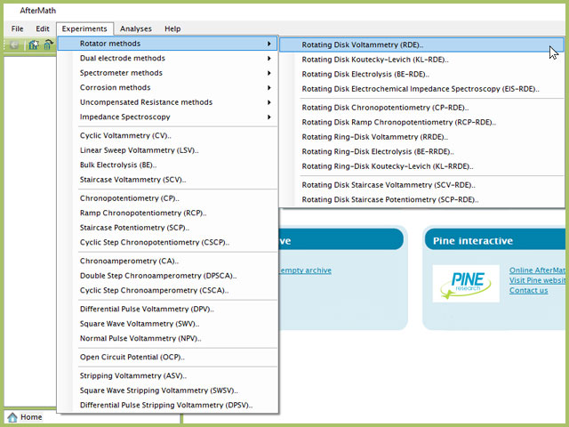
Figure 1. Rotating Disk Voltammetry (RDE) Experiment Menu Selection in AfterMath
In a more advanced rotating electrode experiment, Rotating Ring-Disk Koutecky Levich (KL-RRDE),
 Private: Rotating Ring-Disk Koutecky-Levich Series (KL-RRDE)
there could be several options to control the rotation rate functions during electrochemical experiments (see Figure 2).
Private: Rotating Ring-Disk Koutecky-Levich Series (KL-RRDE)
there could be several options to control the rotation rate functions during electrochemical experiments (see Figure 2).
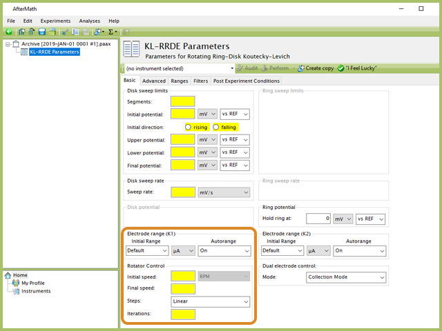
Figure 2. Rotating Ring-Disk Koutecky-Levich Experiment in AfterMath Highlighting Rotator Control Options
Taking a closer look at the rotation parameters, the fields in the example below specify that in this experiment, the connected potentiostat will output appropriate signals, via a special cable interfacing the potentiostat and rotator to automate the control of the rotator (see Figure 3). AfterMath assumes that the connected rotator has been set to expect a signal voltage, proportional to rotation rate, as

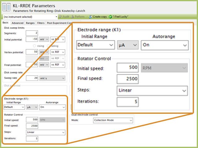
Figure 3. KL-RRDE Parameters Highlighting Advanced Rotator Control Fields
Based on the example in Figure 3, during the experiment, AfterMath directs the potentiostat to output a corresponding voltage on its analog output line,

This will continue for a total of five iterations, ending with the potentiostat outputting 2.5 V.
3Automation with WaveVortex 10 Electrode Rotator
The WaveVortex 10 Electrode Rotator can be controlled by Pine Research potentiostats with the appropriate accessory cable.
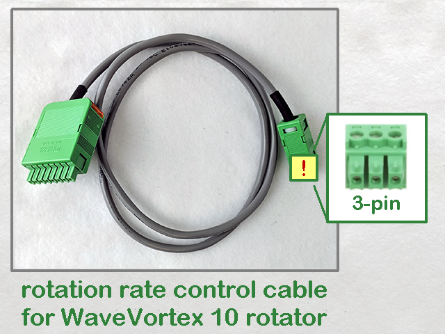 WaveVortex 10 Rate Control Cable (3-pin)
This cable (part number AKCABLE7-03) has a male Rotator B connector block on one end and a male WaveVortex 10 I/O connector block on the other (see Figure 4).
WaveVortex 10 Rate Control Cable (3-pin)
This cable (part number AKCABLE7-03) has a male Rotator B connector block on one end and a male WaveVortex 10 I/O connector block on the other (see Figure 4).
WaveVortex 10 Rate Control Cable (3-pin)
This cable (part number AKCABLE7-03) has a male Rotator B connector block on one end and a male WaveVortex 10 I/O connector block on the other (see Figure 4).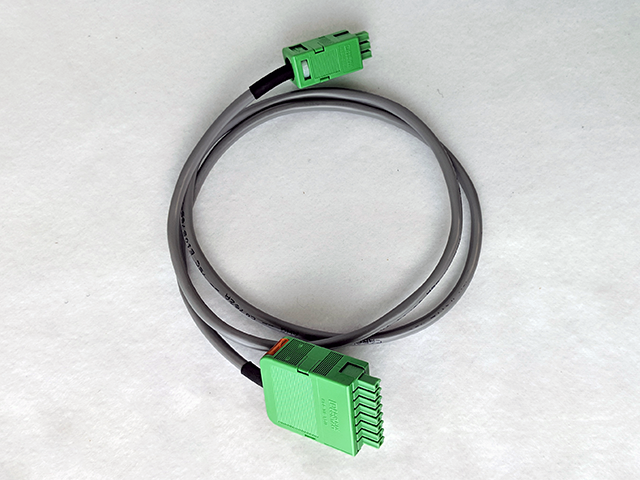
Figure 4. WaveVortex 10 Rotation Rate Control Cable
This control cable interfaces the Pine Research WaveNow series
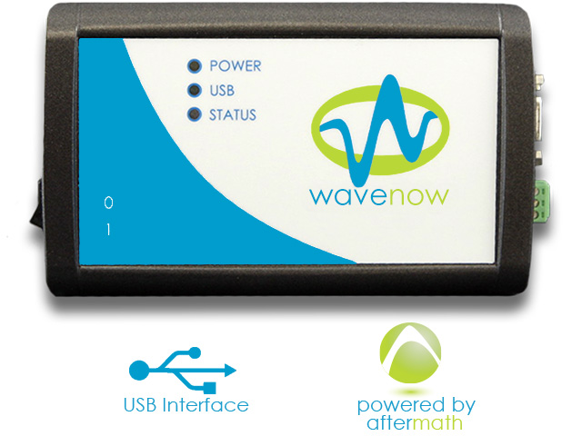 Classic WaveNow Potentiostat
and WaveDriver
Classic WaveNow Potentiostat
and WaveDriver
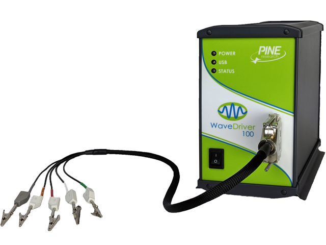 WaveDriver 100 EIS Potentiostat Basic Bundle
series potentiostats Rotator Connector B to I/O connector on the WaveVortex 10 (see Figure 5).
WaveDriver 100 EIS Potentiostat Basic Bundle
series potentiostats Rotator Connector B to I/O connector on the WaveVortex 10 (see Figure 5).
Classic WaveNow Potentiostat
and WaveDriver
WaveDriver 100 EIS Potentiostat Basic Bundle
series potentiostats Rotator Connector B to I/O connector on the WaveVortex 10 (see Figure 5).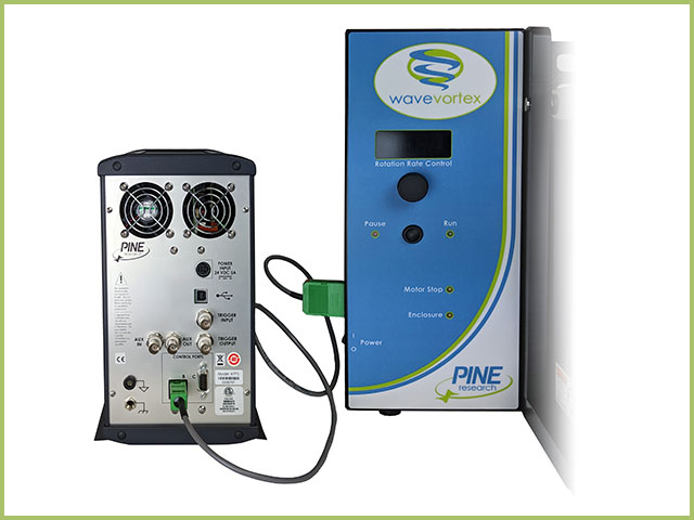
Figure 5. WaveDriver 100 Connected to WaveVortex 10
Via Connector B on modern Pine Research potentiostasts, three signal lines are available: analog signal ground, digital rotator enable signal and analog rotation rate control signal. With the specified cable, the three signals are then appropriately linked to the I/O connector on the WaveVortex 10 (see Figure 6).
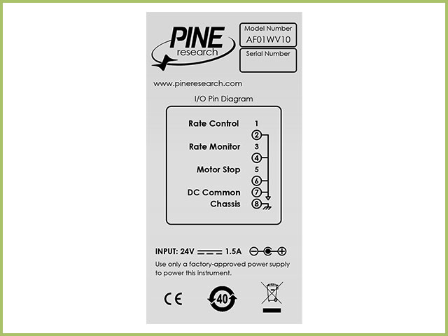
Figure 6. WaveVortex 10 Rotator I/O Port Pinout Label
On the WaveVortex 10, the analog signal ground from the Pine Research potentiostat maps to one of the DC common pins in the I/O port, the digital rotator enable signal maps to the Motor Stop pin on position 5, and the analog rotation rate control signal maps to the Rate Control pin on position 1. The DC common is ground and the rate control is the analog output voltage (from the potentiostat, software controlled). When using a Pine Research potentiostat and control software AfterMath, the analog output voltage corresponds to 1 RPM/mV.
The third line in this cable, the digital rotator enable signal, is a digital signal that can be used to bring the motor to a complete stop. This digital signal can be configured for either “active HIGH” or “active LOW” logic. This signal is a TTL-type digital logic signal with a voltage level that is measured versus the DC Common. The WaveVortex 10 is shipped from production with the "active HIGH" logic enabled. Users can change this logic to "active LOW" as desired.
Change Rotator Motor Stop Signal Logic
The MOTOR STOP indicator on the front panel of the WaveVortex 10 illuminates when an external instrument (such as a potentiostat) sends a digital signal on this line to the WaveVortex to halt rotation (see Figure 7). If this LED indicator is illuminated, then the motor will not rotate.
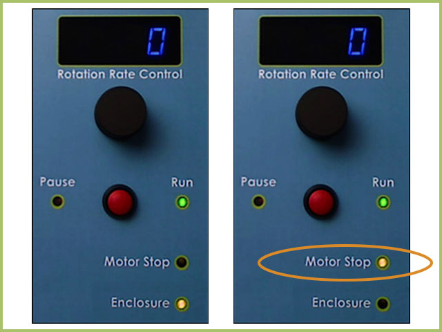
Figure 7. WaveVortex Motor Stop LED