


Changing Input Rotation Rate on MSR Rotator
Last Updated: 5/30/19 by Neil Spinner
1Background
As mentioned, it is possible to control the electrode rotation of Pine Research electrode rotators through software control.
 Automated Control of Electrode Rotators
The rotation rate can be controlled by applying an external voltage signal to the input jacks on the front panel of the control unit (MSR) or the side panel of the WaveVortex 10. The proportionality ratio used to convert the applied voltage signal to the rotation rate can be set to one of three different values: 1.0, 2.0 or 4.0 RPM/mV.
Automated Control of Electrode Rotators
The rotation rate can be controlled by applying an external voltage signal to the input jacks on the front panel of the control unit (MSR) or the side panel of the WaveVortex 10. The proportionality ratio used to convert the applied voltage signal to the rotation rate can be set to one of three different values: 1.0, 2.0 or 4.0 RPM/mV.
Normally, the value for the rotation rate ratio is selected to match the control signal provided by a particular potentiostat. When shipped from the factory, the MSR Electrode Rotator
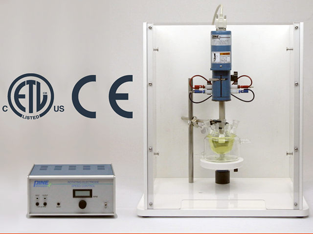 Modulated Speed Rotator (MSR)
is pre-configured with a ratio of 1.0 RPM/mV because this ratio is compatible with Pine Research potentiostat systems.
Modulated Speed Rotator (MSR)
is pre-configured with a ratio of 1.0 RPM/mV because this ratio is compatible with Pine Research potentiostat systems.
Modulated Speed Rotator (MSR)
is pre-configured with a ratio of 1.0 RPM/mV because this ratio is compatible with Pine Research potentiostat systems.
| Input Ratio |
| 1 RPM/mV |
| 2 RPM/mV |
| 4 RPM/mV |
Table 1. Rotation Rate Control Input Ratios
2Changing Input Ratio on MSR Rotator
From production facility, the MSR Rotator is shipped with a ratio of 1 RPM/mV. Should you desire to use this rotator with other potentiostat systems whose software/hardware uses a different ratio, you can change the settings in the lab.
Follow these steps:
- With the power cord disconnected, remove the cover from the control unit (see Figure 1).
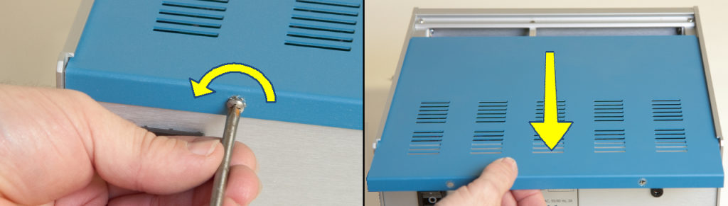
Figure 1. Open MSR Control Unit
- Loosen the screw that secures the main analog board to the front panel, and then carefully remove the analog board (see Figure 2).
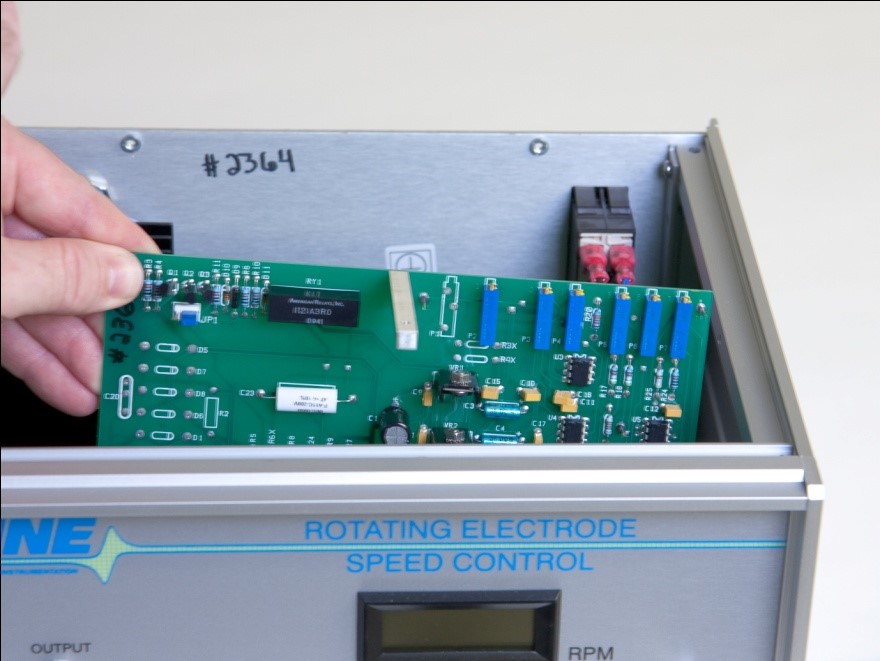
Figure 2. Access the Input Ratio Control Jumpers within the MSR Control Unit
- On the board, locate the configuration pins with the designation JP2. There is a small jumper that can be used to short together one of three pairs of pins (see Figure 3).
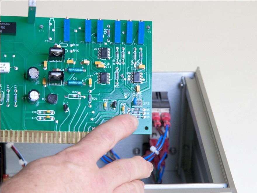
Figure 3. MSR Rotator Control Unit Location of Rate Control Jumpers
- Place the jumper across one of the three pairs of pins at JP2. Choose the ratio required for the particular potentiostat being used with the rotator (see Figure 4).
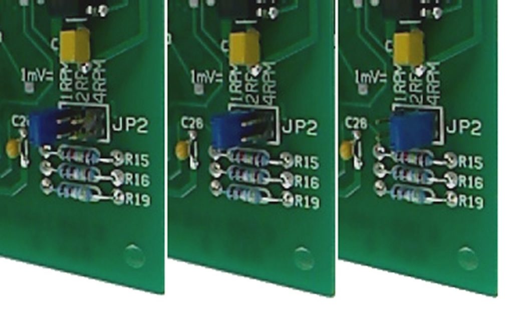
Figure 4. Jumper positions for 1 RPM/mV (Left), 2 RPM/mV (Center), 4 RPM/mV (Right)
- Reinstall the board in the control unit and secure the board to the front panel (see Figure 5).
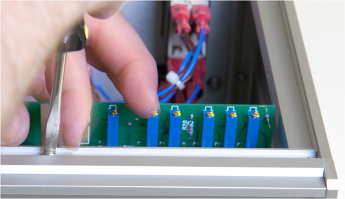
Figure 5. Replace Circuit Board into Control Unit
- Replace the cover on the control unit (see Figure 6).
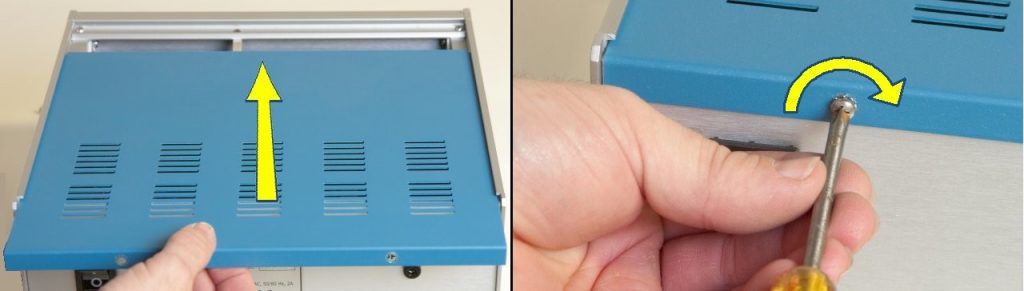
Figure 6. Replace Circuit Board into Control Unit