mobile-main-menu-button
Menu

How can we help? What do you want to learn? Search our knowledgebase.

What is a Potentiostat and how does it work?

Last Updated: 3/6/23 by Neil Spinner

ARTICLE TAGS
  • Bipotentiostat,
  • potentiostat,
  • what is a potentiostat,
  • three electrode,
  • new potentiostat,
  • WaveDriver,
  • wavedriver cable,
  • how does a potentiostat work
Article Contents/Section Navigation
  1. What is a Potentiostat?
    1. Terminology
  2. How does a Potentiostat work?
    1. Operational Amplifiers (Op-Amps)
    2. The Potentiostat Circuit Diagram
    3. Other Electronic Components
  3. Video

1What is a Potentiostat?

A potentiostat is an analytical instrument designed to control the working electrode's potential in a multiple electrode electrochemical cell.  The potentiostat contains many internal circuits that allow it to function in this capacity.  The circuits generate and measure potentials and currents.  External wires in a cell cable connect the potentiostat circuit to the electrodes in the electrochemical cell.  In a conventional three-electrode cell, the cell cable connects to the working, counter (auxiliary), and reference electrodes on one end and the potentiostat cell cable connector on the other end.  The internal circuitry of the potentiostat controls the applied signal.  In the case of potential controlled methods, for example, the working electrode's potential is held with respect to the reference electrode.  At the same time, current flows between working and counter electrodes.  The potentiostat circuit design prevents all but a tiny current from flowing between the working and the high impedance reference electrode.  While modern potentiostats are more complicated than can be explained in this article, a brief introduction to potentiostat circuitry will be discussed to help you understand how a potentiostat works.
Back To Top

1.1Terminology

It's not uncommon that terminology gets confusing when discussing electrochemistry.  Below is a short note on potentiostat terminology.  This can be useful if you are purchasing a potentiostat and want to know all the equipment the potentiostat comes with.  If you are interested in purchasing a potentiostat, you might want to check out our guide to purchasing a potentiostat article.  Additionally we offer a variety of potentiostats for purchase.
 
The name “potentiostat” describes its function. “Potentio” refers to electrical potential, and “stat” stems from the Greek word “stato,” which means standing or set.  As you can control the temperature of a room using a “thermostat,” a potentiostat can control the potential of a single working electrode in a 3-electrode system, and is sometimes referred to as a “single-channel potentiostat.”  A potentiostat where the potential of 2 working electrodes can be controlled independent of each other is referred to as a “bipotentiostat.”  Potentiostats with more than two working electrode channels are referred to as a “Multichannel Potentiostat.”  A galvanostat refers to an instrument that controls the current at an electrode rather than the potential.  Most modern potentiostats have galvanostat functionality built in.  The phrase "electrochemical workstation" also refers to a potentiostat, and to our knowledge, the phrase is only used for marketing purposes.
Back To Top

2How does a Potentiostat work?

The core electronic component of a potentiostat is the operational amplifier, or op-amp for short.  When part of the op-amp output signal is fed into itself, it creates a feedback mechanism.  Feedback is the mechanism by which the potentiostat can control the potential of the working electrode.  Conceptually, one can think about feedback like driving a car.  While driving, you want to maintain a constant distance between you and the car in front of you.  As the distance between you and the car changes, you adjust your speed to maintain a safe distance.  You are using the visual feedback from the car to adjust your speed.  In this analogy, the distance between you and the car is the potential, and changing your car's speed (via slowing down and accelerating) is the op-amp.
Back To Top

2.1Operational Amplifiers (Op-Amps)

An operational amplifier, is an electronic circuit component powered by a DC voltage capable of amplifying an input voltage.  Schematically, the op-amp symbol is a sideways triangle with inputs along the vertical line and the output at the point opposite the inputs (Figure 1).  The voltage input to the op-amp is a differential value between two potential inputs, ∈(non-inverting input) and ∈- (inverting input), both of which are referenced to ground potential.  The open loop gain of the amplifier is a scalar factor (β), and common amplifications are on the order of 105 - 106, dictated by the integrated circuit construction.  The configuration of the external feedback circuitry can lower the gain to a user-selectable value.  Some amplifiers have a fixed gain of 1, and only output the difference between the two input potentials.  The output voltage, Vo , is equal to the product of the gain and the difference in the input voltages (Equation 1).  In practice, several specific details of the op-amp circuit diagram are omitted for clarity (Figure 2).  Notice in the simplified diagram, power supply voltages and circuit common (ground) are omitted and are assumed.
 
\displaystyle{V_o = -\beta(\epsilon _- - \epsilon _+) = -\beta V_i} (1)
 
Operational Amplifier Circuit Diagram

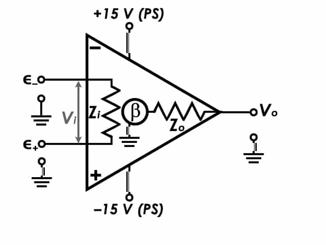
Figure 1: Circuit Diagram of an Operational Amplifier.  In most op-amp circuit diagrams, the positive and negative Power Supply (+PS and -PS) potentials are assumed.  Therefore, in circuit diagrams of op-amps, they are most often omitted.

 
Operational Amplifier or Op-Amp simplified diagram

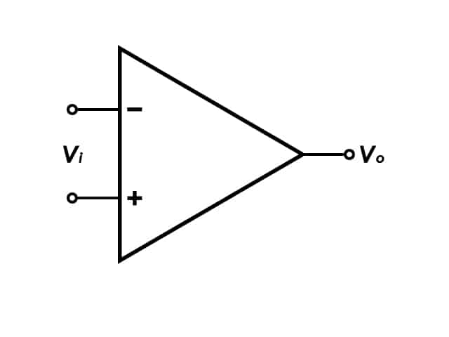
Figure 2: Simplified Circuit Diagram of an Operational Amplifier.


Op-amps have several important characteristics, as follows:
 
  • Small footprint, often measuring < 1 cm2
  • Generally inexpensive and widely available
  • Typically have large gains (β = 104 - 106)
  • High input impedance (Zi ≥ 106 MΩ)
  • Low output impedance (Zo ≤ 1 - 10 Ω)
  • Ideally, zero output for zero input. In practice, there may be an offset voltage, which can be corrected (i.e., trimmed)
  • Intrinsically have high bandwidth, allowing for a wide range of frequency input and output
 
If an op-amp merely amplifies a voltage input, the voltage output can be driven too high.  Due to the large gain, even a small differential voltage input (e.g., Vi = 0.001 V) can amplify the signal to a highly unusable (and possibly dangerous) voltage, limited by the amplifier supply voltage.  To overcome this possibility, the output signal is routed back into the ∈- input, which creates a feedback loop.  When an op-amp uses feedback, it forces ∈- to equal ∈+.  This circuit is called a voltage follower (Figure 3).  In the voltage follower circuit, if ∈+ input increases, so does ∈-.  Since ∈- and Vo are tied together, Vo follows +.  Vi = Vo, thus the reduced gain, β, is 1.
 
Voltage-Follower Operational Amplifier (Op-Amp) Circuit

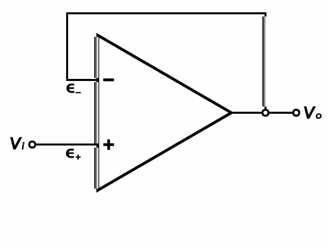
Figure 3: Circuit Diagram of a Voltage Follower

Back To Top

2.2The Potentiostat Circuit Diagram

By understanding how an operational amplifier works we can describe how a potentiostat functions based on the figure below.
 
Simplified Potentiostat Circuit Diagram

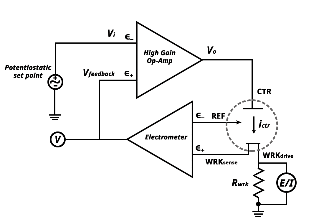
Figure 4. Simplified Potentiostat Circuit Diagram.

Let's start with reviewing the components in the potentiostat diagram above.  Vi represents a user-controlled applied potential called the potentiostatic set point that is referenced to ground.  Vi enters the inverting input (-) on the High Gain Op-Amp.  The output (Vo) connects to the counter electrode lead (CTR).  The reference electrode lead (REF) and the working sense lead (WRKsense) connect to a true difference amplifier called the electrometer.  The output voltage (Vfeedback) from the electrometer feeds into a voltmeter (V) and into the non-inverting input (+) on the High Gain Op-Amp.  The working electrode drive lead (WRKdrive) connects to a sense resistor (Rwrk) that connects to ground.  The voltmeter (E/I), measures the potential across Rwrk, and converts it to a current.  WRKsense and WRKdrive are shorted together and connect to the working electrode of interest.  CTR, REF, WRKsense, and WRKdrive are all cables that come out of the potentiostat and connect to the electrochemical cell.
 
During potentiostat operation, the user applies a voltage Vi to the electrochemical cell.  An output voltage, Vo, comes from the High Gain Op-Amp into the electrochemical cell through the counter electrode (CTR).  The counter electrode passes current (ictr) through the solution to REF, WRKsense, and WRKdrive.  Remember that the inputs to an operational amplifier have a high impedance, hence no current passes through them.  Since the REF and WRKsense are connected to a high impedance operational amplifier, the only viable path for the current to flow is through WRKdrive.
 
The electrometer output voltage is the voltage difference between the REF and WRKsense.  As the current travels between the CTR and WRKdrive, the voltage drops across a gradient that is proportional to the bulk solution resistance.  This process affects the potential of REF and WRKsense.  However, reference electrodes are designed to maintain a stable potential, and the potential at REF remains constant.  This means that any measured changes in the potential come from WRKsense.  The voltage difference between REF and WRKsense is the output voltage of the electrometer, VfeedbackVfeedback feeds into a voltmeter (V) to measure the difference between the REF and WRKsense.  It also feeds into the non-inverting (+) input of the High Gain Op-Amp.  Recall, that the High Gain Op-Amp amplifies the difference between + and - (equation 1).  If Vfeedback is not equal to Vi, the op-amp will either increase or decrease Vo until they are equal.
 
Finally, note that in the design of the potentiostat, working electrode current is not directly measured.  Rather, the voltage is measured across Rwrk which is located between WRKdrive and ground.  Rwrk is a known resistor, so based on the voltage measured across it, we can calculate the measured current via Ohm's Law.
 
 
\displaystyle{i = \frac{V}{R_{wrk}}} (2)
 
Where i is the current, V is the voltage, and Rwrk is the known resistor between WRKdrive and ground.  In summary, the current at the working electrode is measured by voltmeter (E/I) across Rwrk, the potential at the working electrode is measured by the electrometer (V), and the applied potential is determined by the potentiostatic set point.  By utilizing the op-amp's feedback mechanism, the potential of the working electrode with respect to the reference electrode can be adjusted.  Simultaneously adjusting potential while measuring the current at the working electrode is the heart of voltammetry techniques.
Back To Top

2.3Other Electronic Components

The operational amplifier and its feedback mechanism are critical for proper potential control of the working electrode with respect to the reference electrode (in controlled potential methods).  Additional electronic components of a potentiostat include a function generator, analog to digital (A/D) converters, and digital to analog (D/A) converters.
 
Modern instrumentation routinely translates between true analog responses and their digital equivalent.  Electrochemical experiments generate analog data (current and voltage), data which are continuous and can take on any value.  Computers require digital data, represented with zeroes and ones.  A/D converters rely upon the instrumentation calibration to accurately translate analog signals to digital signals.  The opposite is true, that D/A converters translate digital signals into continuous analog signals.  In the case of a potentiostat, current response (an analog signal) passes through an A/D converter, where the computer is able to plot and manipulate data.  At the same time, digital waveforms generated by the computer pass through a D/A converter, such that the waveform is applied as an analog signal to the electrochemical cell.
 
Modern potentiostats include all electronic components—op-amps, waveform generators, D/A and A/D converters—in one instrument.  In general, a researcher only requires a potentiostat, which is often USB-interfaced with a computer equipped with the potentiostat software.   In summary, D/A and A/D converters allow users to apply and measure potential and current values using a computer.
Back To Top

3Video

 
Back To Top
Questions? Find Answers.

Our knowledgebase is the central repository for written content, including help topics, theory, application notes, specifications, and software information.

Select a category below or view the Knowledgebase home page
Software

Detailed information about our Software, which includes AfterMath and retired PineChem.

Applications

Application notes discuss practical aspects of conducting specific experiments.

Theory

Fundamental electrochemical theory presented in a brief and targeted manner.

Product Specifications

Review complete product specifications and compare products within a category here.