This article is part of the Pine WaveDriver Potentiostat User's Guide[/call_to_action]
This article describes how to make connections from a WaveDriver potentiostat to several different kinds of electrochemical cells. Users should be familiar with the cell cable color coding scheme used by Pine. Examples below include a traditional three-electrode cell, a rotating disk electrode (RDE), a rotating ring-disk electrode, and a simple two electrode configuration.
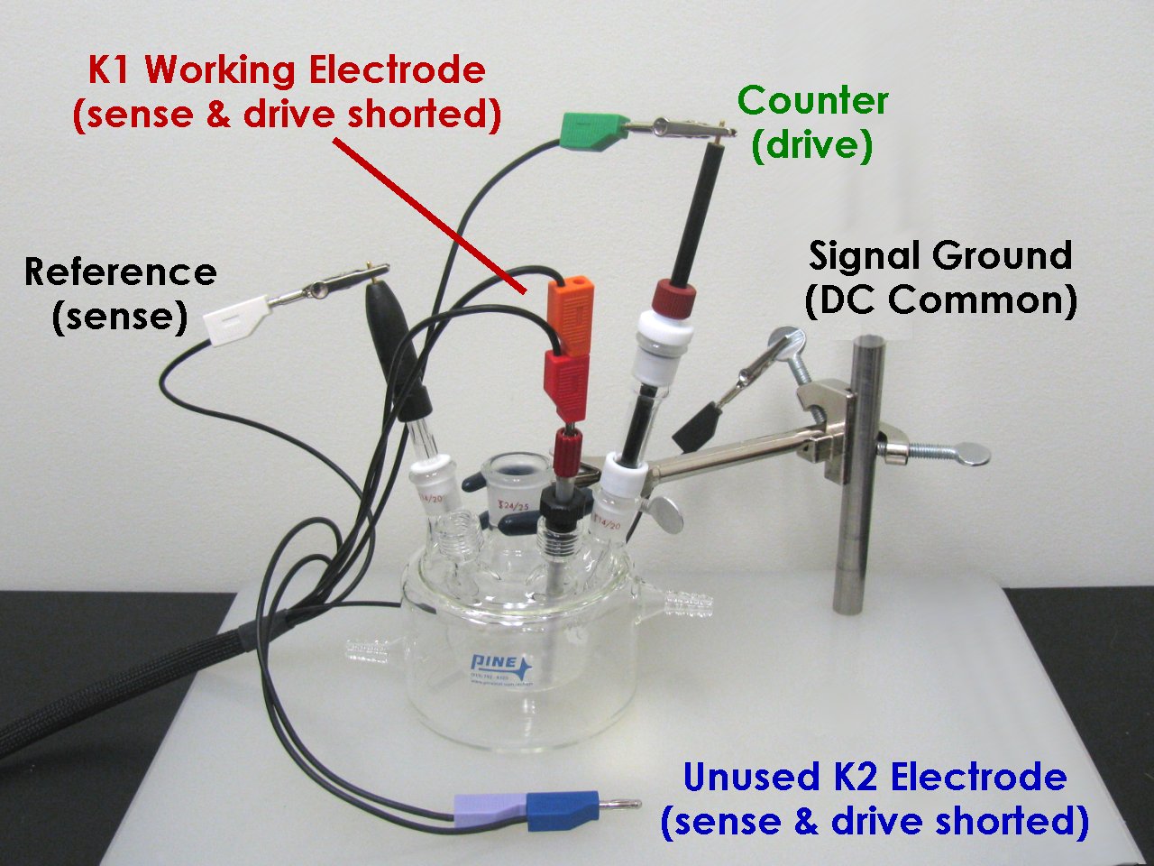
In traditional three-electrode voltammetry, the electrochemical cell consists of three electrodes (counter, reference, and working) placed in an electrolyte solution. The primary current path through the cell is between the counter electrode and the working electrode, and potential is measured between the reference electrode and the working electrode. The photo below shows how to properly connect the potentiostat cell cable to this type of electrochemical cell.
One of the most important connections is the signal ground (BLACK). Any metal object near the electrochemical cell (Faraday cage, clamp, ring stand, etc.) should be grounded to help prevent noise from interfering with the electrochemical measurement. In the photo below, the signal ground has been connected to the metal clamp holding the electrochemical cell.
In the photo above, the counter electrode (drive) line is the coaxial cable which terminates at a GREEN banana plug, and the working electrode (drive) line is the cable which terminates at a RED banana plug. These are both low-impedance connections which the potentiostat uses to drive current through the cell.
While driving current through the cell, the potentiostat also measures (senses) the potential between the working electrode and the reference electrode. In the photo above, the cable terminating at an ORANGE banana plug is the working electrode (sense) line, and the cable terminating at a WHITE banana plug is the reference electrode (sense) line. These are both high-impedance connections carrying a negligible amount of current.
Note that two cables (sense and drive) are connected to the working electrode. Typically, the working electrode sense and drive signals are shorted together at a point very near the electrochemical cell. Failure to connect both of these cables to the working electrode will prevent the potentiostat from properly controlling the electrochemical cell. Shorting these two cables together is a simple matter of pushing the ORANGE banana plug (sense) into the back of the RED banana plug (drive) as shown below.
Working Electrode Sense & Drive Shorted Together near Cell
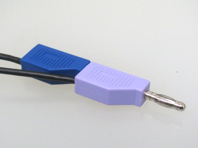
When working with a bipotentiostat, the cell cable will provide two pairs of working electrode connections, one pair for the primary working electrode (K1) and another pair for the secondary working electrode (K2). When using a bipotentiostat with a traditional three-electrode cell, always use the primary working electrode connections (ORANGE and RED) to connect to the working electrode. The (unused) secondary working electrode connections (VIOLET and BLUE) should be shorted together but should not be connected to any electrode. Simply lay them to the side on the lab bench as shown in the photo below.
Unused Secondary Working Electrode (K2) Connections
(sense and drive are shorted together but not connected to any electrode)
In a rotating disk electrode (or a rotating cylinder electrode) experiment, the counter and reference electrode connections are made in the manner described above for traditional three-electrode voltammetry. Connections to the rotating electrode, however, are made via spring-loaded brush contacts which push against the rotating shaft.
As an example, on the very popular Pine MSR Rotator system, there are two pairs of opposing brushes on either side of the rotating shaft. The upper pair of brush contacts (red) is used to make electrical contact with a rotating disk electrode (RDE) or a rotating cylinder electrode (RCE).
To make good contact on opposite sides of the rotating shaft, both of the red brushes (left and right sides) should be used. Use a short banana jumper cable to connect the opposing brushes together (see photo above), and then connect the working electrode sense and drive cables (RED and ORANGE) to the short jumper cable.
More information about rotating disk voltammetry may be found at the following links:
It is usually desirable to configure the potentiostat so that it can control the rotation rate during RDE and RCE experiments. This is accomplished by connecting the rotator to the potentiostat using a special rotation rate control cable (Pine part number AKCABLE4). One end of this cable is connected to Control Port B on the back panel of the WaveDriver (see photos below).
The other end of the control cable is connected to the rotator motor controller. The photos above show the proper connections when using the WaveDriver to control a Pine MSR rotator. The cable has a single banana cable which plugs into the back panel of the motor controller (into the blue MOTOR STOP jack). The cable also has a coaxial cable (with a dual banana adapter) which plugs into the front panel (into the INPUT jacks).
When connecting the WaveDriver to rotators other than the Pine MSR rotator, it is important to consider the proportionality between the WaveDriver rate control signal (1 RPM/mV) and the proportionality expected by the rotator. This topic is discussed in more detail at the link below:
https://pineresearch.com/shop/knowledgebase/pine-msr-user-operation/#rotation_rate_control
More information about rotating disk voltammetry may be found at the following links:
In a rotating ring-disk electrode (RRDE) experiment, the counter and reference electrode connections are made in the manner described above for traditional three-electrode voltammetry, and the connection to the rotating disk electrode is made in manner described above for a rotating disk electrode (RDE). The rotator usually has one or more brushes which contact the disk electrode and additional brushes which contact the ring electrode.
Using the Pine MSR Rotator system as an example, there are two pairs of opposing brushes on either side of the rotating shaft. The upper pair of brush contacts (RED) is used to make electrical contact with the disk electrode while the lower pair of brushes (BLUE) makes contact with the ring electrode.
To make good contact on opposite sides of the rotating shaft, both of the red brushes (left and right sides) should be used to contact the disk, and both of the blue brushes should be used to contact the ring. Use short banana jumper cables to connect the opposing brushes together (see photo above). Connect the primary working electrode (K1) cables to the disk electrode (RED and ORANGE cables) connect to the upper pair of brushes). Connect the secondary working electrode (K2) cables to the ring electrode (BLUE and VIOLET cables) to the lower pair of brushes).
More information about rotating ring-disk voltammetry may be found at the following links:
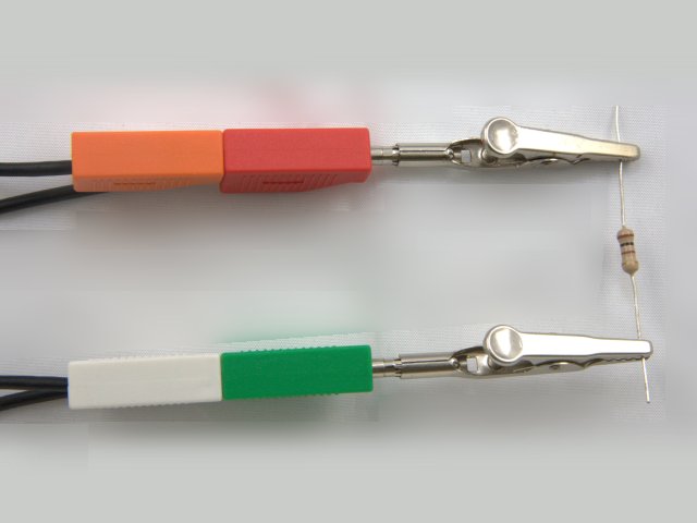
In some electrochemical experiments there may only two electrodes in the cell. Examples include experiments with ion-selective electrodes (where the open circuit potential is measured between the ISE and a reference electrode) or solid-state experiments where the electrochemical behavior across a single interface is being probed.
For such two electrode experiments, the counter (GREEN) and reference (WHITE) banana jacks should be shorted together and connected to one of the electrodes (i.e., the reference electrode). In addition the working electrode drive (RED) and sense (ORANGE) banana jacks should be shorted together and connected to the other electrode. An example is shown below where the “cell” is just a simple resistor.
Related Links: Electrochemist's Guide to AfterMath, AfterMath Support Site, WaveDriver Support Site
[/toggle]


