


General Electrochemistry
Back to General Electrochemistry Back to Applications Back to Knowledgebase Home1Overview
This document describes the procedure for testing the electrical connections of shafts, rotating ring-disk electrode tips, rotating cylinder electrodes, and rotating disk electrode tips. These simple tests can help isolate electrical problems with electrode instrumentation. Electrical problems can arise as a result of accidental damage (e.g., dropping the tip or shaft from a significant height, such as rolling off the lab bench) or in some cases, can arise from heavy chemical contamination and/or corrosion. This document describes how to make some electrical measurements of shafts and electrodes. These tests can be performed with a simple multimeter by measuring the resistance across two probes.
2Electrical Isolation Guide
The document herein uses three colors (red, blue, and green) to differentiate electrically isolated sections of rotating ring-disk electrodes (RRDEs), rotating cylinder electrodes (RCEs), and rotating disk electrodes (RDEs). The three colors are also used to differentiate the electrically-isolated sections of their respective shafts. Red corresponds to the section of the shaft that connects to the rotator, blue corresponds to the section of the electrode/shaft that connects to and controls the disk or cylinder, and green corresponds to the section of the electrode/shaft that connects to and controls the ring. Additionally, letters A-F are used to describe distinct sections of a shaft or electrode (see Table 1).
| Letter | Color | Description |
| A | Red | Rotator connection section of shaft (electrically-isolated) |
| B | Blue | Disk/cylinder electrical connection section of shaft |
| C | Green | Ring electrical connection section of shaft |
| D | Blue | Disk electrical connection section of an RDE/RRDE tip |
| E | Blue | RDE and/or RRDE electrode tip disk/RCE cylinder |
| F | Green | Ring electrical connection section of an RRDE tip |
| G | Green | RRDE electrode tip ring |
Table 1. Description of Color and Letter Used to Describe Electrically-Isolated Sections.
If any of the test measurements are not as described in this document, contact Pine Research to discuss the test results. In some cases, the tip and/or shaft may be irreversibly damaged and must be replaced. In other cases, our production team may be able to attempt a repair. In the latter case, Pine Research will issue an RMA for service.
3Rotating Ring-Disk Electrodes (RRDE)
3.1Electrical Test for AFE6M/AFE6MB Shaft
RRDE shafts are divided into three electrically-isolated sections (see Figure 1). Section A of the shaft connects to the rotator while sections B and C connect to the disk and ring, respectively. The resistance between these sections should be infinity. To test the shaft, use a multimeter to measure the resistance between the connections, as follows.
- The resistance between A and B should be infinity
- The resistance between B and C should be infinity
- The resistance between A and C should be infinity
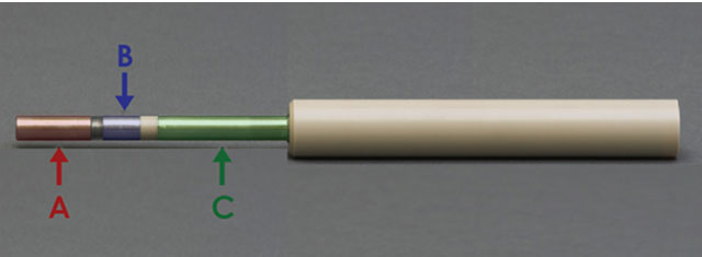
Figure 1. RRDE Shaft with Electrically-Isolated Sections Labeled
3.2Electrical Test for Rotating Ring-Disk Electrode Tips (E6, E7, and E8 Series)
The RRDE tip is detachable from the shaft. As such, there are electrical sections within the tip that enable the ring and disk electrode surfaces to electrically contact the shaft, yet remain isolated from each other. The disk electrode E is in electrical contact with the threaded pin D (see Figure 2). The ring electrode G is in electrical contact with the threaded end of the tip F (see Figure 2). Use a multimeter to measure the resistance between these connections, as follows.
- The resistance between D and E should be less than 10 Ω
- The resistance between F and G should be less than 10 Ω
- The resistance between D and F should be infinity
- The resistance between E and G should be infinity
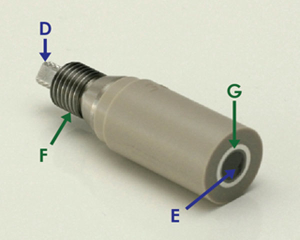
Figure 2. RRDE Tip with Electrical Connections Labeled
4Rotating Disk Electrodes (RDE)
4.1Electrical Test for AFE3M Shaft
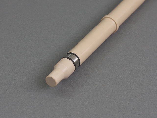
The AFE3M shaft
 Standard 12 mm RDE/RCE Shaft
has two electrically-isolated sections, A and B (see Figure 3). Section A of the shaft connects to the rotator while section B connects to the disk. The resistance between these sections should be infinity. To test the shaft, use a multimeter to measure the resistance between the connections, as follows:
Standard 12 mm RDE/RCE Shaft
has two electrically-isolated sections, A and B (see Figure 3). Section A of the shaft connects to the rotator while section B connects to the disk. The resistance between these sections should be infinity. To test the shaft, use a multimeter to measure the resistance between the connections, as follows:- The resistance between A and B should be infinity
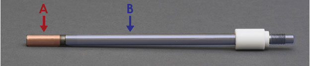
Figure 3. RDE Shaft with Isolated Electrical Connections Labeled
4.2Electrical Test for RDE Tips (E3, E5, E5TQ, and E6TQ Series)
There are two sizes of RDE tips available for purchase from Pine Research: 12 mm OD (E3 series)
 E3 Fixed-Disk RDE Tips PTFE
and 15 mm OD (E5,
E3 Fixed-Disk RDE Tips PTFE
and 15 mm OD (E5,
 E5 Fixed-Disk RDE Tips PTFE
E5TQ,
E5 Fixed-Disk RDE Tips PTFE
E5TQ,
 E5TQ ChangeDisk RDE Tip PTFE
and E5TQPK
E5TQ ChangeDisk RDE Tip PTFE
and E5TQPK
 E5TQ ChangeDisk RDE Tip PEEK
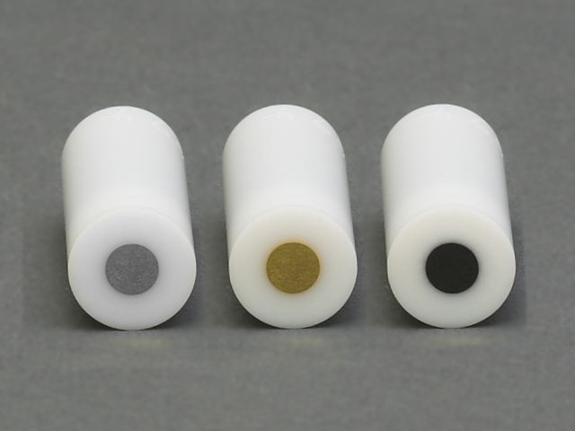
series). For the 12 mm OD tip, the disk electrode E is electrically-coupled to the female threading D (see Figure 4a and Figure 4b). For the 15 mm OD tip, the disk electrode E is electrically-coupled to threaded pin D (see Figure 4c). The resistance between D and E of RDE tips should be fairly small. Use a multimeter to measure the resistance between these connections, as follows.
E5TQ ChangeDisk RDE Tip PEEK
series). For the 12 mm OD tip, the disk electrode E is electrically-coupled to the female threading D (see Figure 4a and Figure 4b). For the 15 mm OD tip, the disk electrode E is electrically-coupled to threaded pin D (see Figure 4c). The resistance between D and E of RDE tips should be fairly small. Use a multimeter to measure the resistance between these connections, as follows.
E3 Fixed-Disk RDE Tips PTFE
and 15 mm OD (E5,
E5 Fixed-Disk RDE Tips PTFE
E5TQ,
E5TQ ChangeDisk RDE Tip PTFE
and E5TQPK
E5TQ ChangeDisk RDE Tip PEEK
series). For the 12 mm OD tip, the disk electrode E is electrically-coupled to the female threading D (see Figure 4a and Figure 4b). For the 15 mm OD tip, the disk electrode E is electrically-coupled to threaded pin D (see Figure 4c). The resistance between D and E of RDE tips should be fairly small. Use a multimeter to measure the resistance between these connections, as follows.- The resistance between D and E on the shaft should be less than 10 Ω
- The resistance between D and E on the shaft should be less than 10 Ω
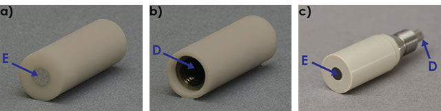
Figure 4. a) Front and b) Back of a 12 mm OD RDE tip and c) a 15 mm OD RDE Tip Showing Electrical Isolation
5Rotating Cylinder Electrodes (RCE)
Pine Research manufactures two different shafts to be used in conjunction with 15 mm and 12 mm cylinder inserts (part numbers AFE9MBA
 Precision 15 mm Single RCE Shaft
and AFE3M,
Standard 12 mm RDE/RCE Shaft
respectively). The latter shaft, AFE3M, was discussed in section 4.1.
Precision 15 mm Single RCE Shaft
and AFE3M,
Standard 12 mm RDE/RCE Shaft
respectively). The latter shaft, AFE3M, was discussed in section 4.1.
Precision 15 mm Single RCE Shaft
and AFE3M,
Standard 12 mm RDE/RCE Shaft
respectively). The latter shaft, AFE3M, was discussed in section 4.1. 5.1Electrical Test for AFE9MBA Shaft
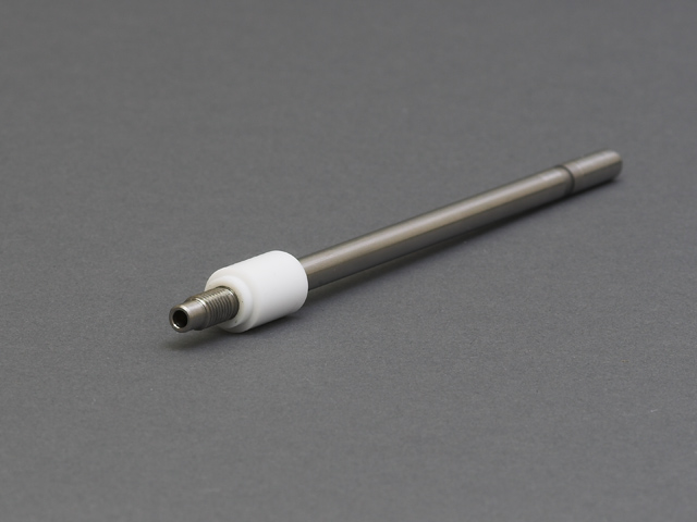
The AFE9MBA
Precision 15 mm Single RCE Shaft
shaft has two electrically-isolated sections, A and B (see Figure 5). Section A of the shaft connects to the rotator while section B connects to the cylinder. The resistance between these sections should be infinity. To test the shaft, use a multimeter to measure the resistance between the connections, as follows:
Precision 15 mm Single RCE Shaft
shaft has two electrically-isolated sections, A and B (see Figure 5). Section A of the shaft connects to the rotator while section B connects to the cylinder. The resistance between these sections should be infinity. To test the shaft, use a multimeter to measure the resistance between the connections, as follows:- The resistance between A and B should be infinity
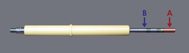
Figure 5. RCE Shaft with Electrically-Isolated Sections Labeled
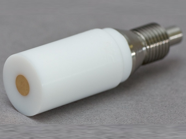
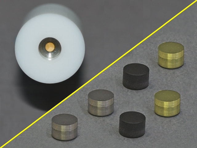
5.2Electrical Test for 15 mm RCE Tips (E9 Series)
The cylinder E slides directly onto the lower threaded of the shaft, coupled to section B (see Figure 6). Thus, the resistance between shaft section B and cylinder E should be minimal while the resistance between shaft section A and cylinder E should be infinity for the 15 mm OD RCE. Use a multimeter to measure the resistance between these sections as follows:
- The resistance between A and E should be infinity
- The resistance between B and E should be less than 10 Ω
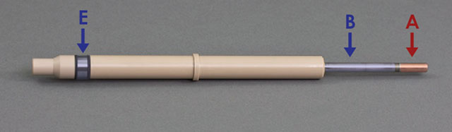
Figure 6. Electrical Isolation Labeled with Cylinder Inserted on Shaft AFE9MBA
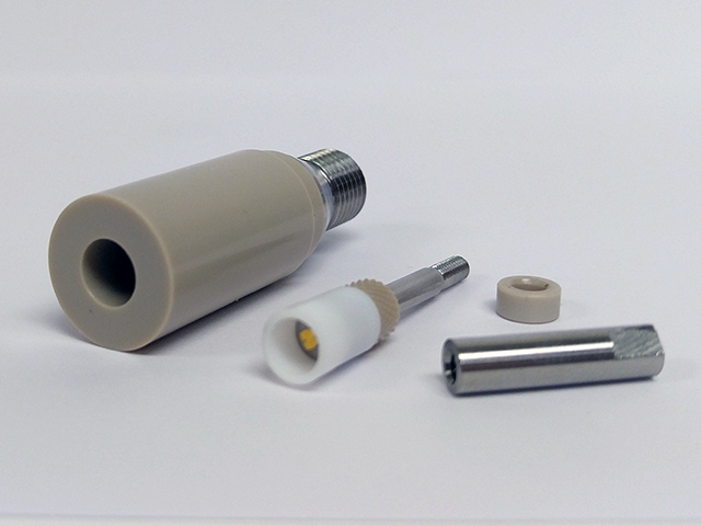
5.3Electrical Test for 12 mm RCE Tips (ACQC Series)
The 12 mm RCE tip is detachable from the AFE3M shaft. For the cylinder to make electrical connection to the AFE3M shaft, the threading D is electrically connected to cylinder E on the RCE tip. Use a multimeter to measure the resistance between these sections, as follows:
- The resistance between D and E should be less than 10 Ω
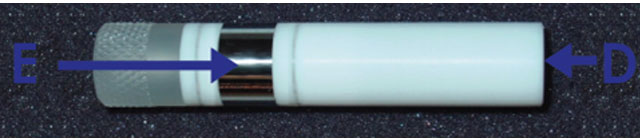
Figure 7. RCE Shaft with Electrically-Isolated Sections Labeled