1Background
The Stirring Automation Pack,
designed to complement EChem in a Box,
is useful for electrochemical methods that utilize stirring. For example, EChem in a Box includes an educational laboratory exercise for determination of lead in tap water,
in which students are routinely asked to conduct stirring throughout various parts of the Differential Pulse Stripping Voltammetry experiment.
It is important that this stirring is consistent for each step. It can be complicated (especially for an undergraduate student) to properly time stirring with the electrochemical sequence. To address this, Pine Research offers an optional add-on to automate the stirring in this expeirment. The solution is to combine some third party products with a special cable that links a small stir plate to the WaveNow
(or WaveDriver) potentiostat.
2Contents
The Stirring Automation Pack consists of three components: Block Connector Wire Assembly, LowProile Magnetic Stirrer, and a TTL Enabled AC Switch. Together, with a Pine Research potentiostat, users can automate control of an external stirrer, via the rotation rate connector on the potentiostat.
2.1Block Connector Wire Assembly - AC01SPECT1-03
The Block Connector Wire Assembly links the Pine Research potentiostat with the TTL Enabled AC Switch. This is a simple cable where one end is a standard three-block green connector which terminates with two wire leads at the other end. These leads are red (signal) and black (DC Common/ground) (see Figure 1).
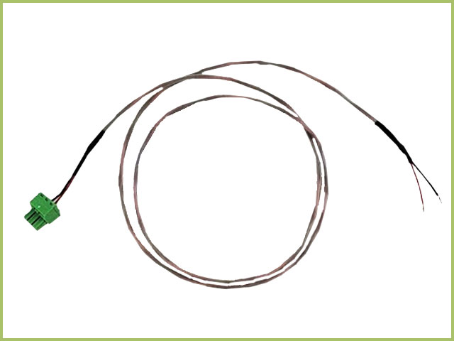
Figure 1. AC01SPECT1-03 Automated Stirring Connection Cable
INFO: The image in Figure 1 shows the cable terminating with black and red wires. At one point, the cable terminated with black and clear wires. In any case, black is always black (ground) and red = clear and is always signal.
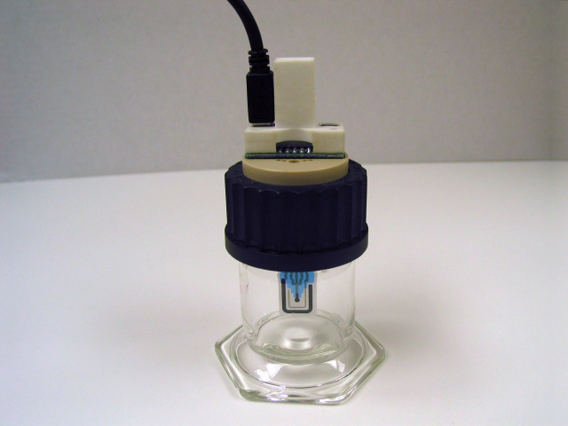
2.2LowProfile Magnetic Stirrer - RRSTIRRER
A low cost and LowProfile magnetic stirrer is included in this kit. This simple stirrer has a speed range of 300 - 1800 RPM, which is set by the large dial on the front of the unit. The stirrer includes an AC adapter and various plug adapters. This magnetic stir plate is the perfect size to hold the larger volume SPE cell
(see Figure 2).
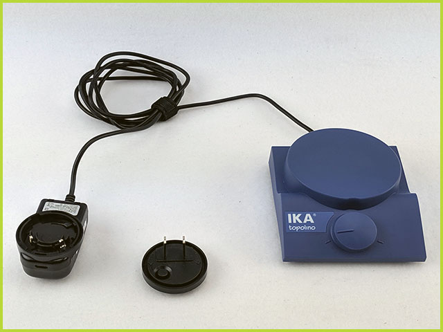
Figure 2. LowProfile Magnetic Stirrer
To enable automation, the stirrer power cable is plugged into one end of the TTL Enabled AC Switch, instead of into the wall directly.
2.3TTL Enabled AC Switch - RRSWITCH
The central aspect of automation is the TTL Enabled AC Switch. This product is placed in between the AC Mains and the stirrer. When the switch receives an analog signal > 3 V, it will engage the switch and allow the AC mains to pass through the switch and power what is connected at the other end of the block. When the switch is not receiving an analog TTL signal, then the block is open, preventing passage of the AC mains and leaving the item plugged into the opposite end without power (see Figure 3).
INFO: The TTL Enabled Switch (RRSWITCH) has changed over the course of this product. Figure 3 shows the legacy TTL Enabled Switch while Figure 4 shows the current TTL Enabled Switch. With slightly different configurations and operating procedures, the two switches enable the same behavior, which is to use the roator control port on Pine Research potentiostats to input a signal to the switch, sufficient to close the relay and provide power to the device connected (e.g., magnetic stirrer).
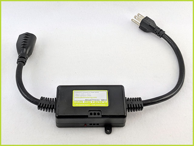
Figure 3. Legacy Version TTL Enabled AC Switch - RRSWITCH
Starting in 2019, Pine Research changed the vendor for the TTL enabled AC Switch (Figure 4). The replacement switch expands the capabilities of the switch (for other applications, as desired), but provides the same function as the legacy TTL enabled AC Switch (Figure 3). The current TTL enabled Switch has four plugs as follows:
- "normally OFF" - there are two of these outlets on the switch. Devices whose power cords are plugged into these outlets will not be powered unless the switch is active, i.e., a signal of at least 3 V is received by the switch, as indicated by the "switch active" light illuminated. An audible click (relay) can be heard when the unit receives the appropriate switch signal.
- "always ON" - there is one outlet of this style on the switch. Devices whose power cords are plugged into this outlet will always receive power from the AC mains, as if the switch was absent. In other words, the switch has no effect over devices whose power cords are plugged into this outlet.
- "normally ON" - there is one outlet of this style on the switch. Devices whose power cords are plugged into this outlet will be powered unless the switch is active, i.e., a signal of at least 3 V is received by the switch, as indicated by the "switch active" light illuminated. An audible click (relay) can be heard when the unit receives the appropriate switch signal.
For the "Automated Stirring" application described here, only one of the "normally OFF" outlets will be used.
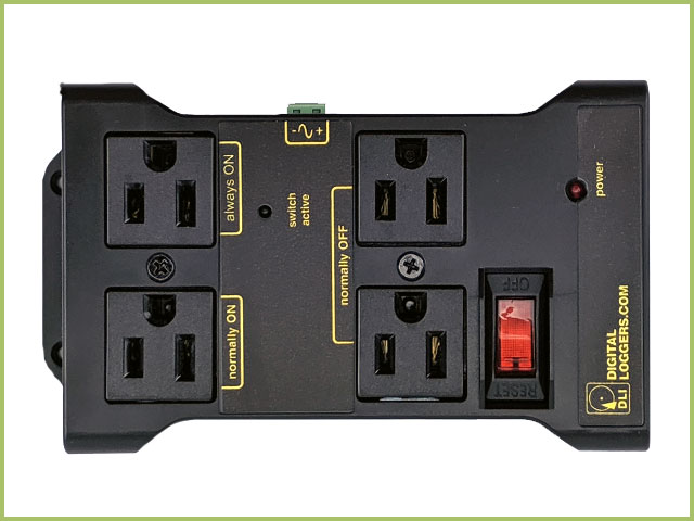
Figure 4. Current Version TTL Enabled AC Switch - RRSWITCH
3Setting Up Connections
Starting from the wall outlet (AC Mains), the components of the Stirring Automation Pack are connected in the following fashion:
AC Mains → TTL Enabled AC Switch → Low Profile Magnetic Stirrier
↑ Block Connector Wire Assembly
↑ Pine Research Potentiostat
This is the general diagram for any system automated stirring pack you have.
3.1Step 1 - Connect Block Connector Wire to TTL Switch
Pine Research has provided more than one version of the TTL Switch. As of last update, at least two versions have been released -- the legacy version switch (see Figure 3) and the current version switch (see Figure 4). Below are instructions for setting up either switch.
3.1.1Current Version TTL Switch Setup
The green block on the Pine Research potentiostat contains three signals, signal (0 - 10 V), ground (DC common), and a Rotator Enable Signal (not used with stirring). The block connector wire assembly breaks out the signal and ground lines from the Pine Research potentiostat and terminates them in wires, which are connected directly to the TTL Enabled AC Switch as shown (see Figure 5).
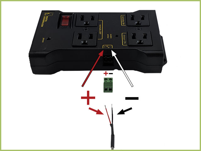
Figure 5. RRSWITCH - Current Version - TTL Enabled AC Switch
There are two positions to receive a wire in the switch. From left to right, as shown in Figure 5, the positions are for signal (red, +) and ground (black, -). The red wire should be installed in the left-most position and the black wire should be installed in the right position. To install, use a slim flat screwdriver to loosen the clamp for the left and right positions. Slide the wire into the appropriate position. Hold in place while screwing down the connector (see Figure 6). Once the wires are installed into the green block connector, slide the connector into the TTL switch. The plug will only fit in one position/orientation.
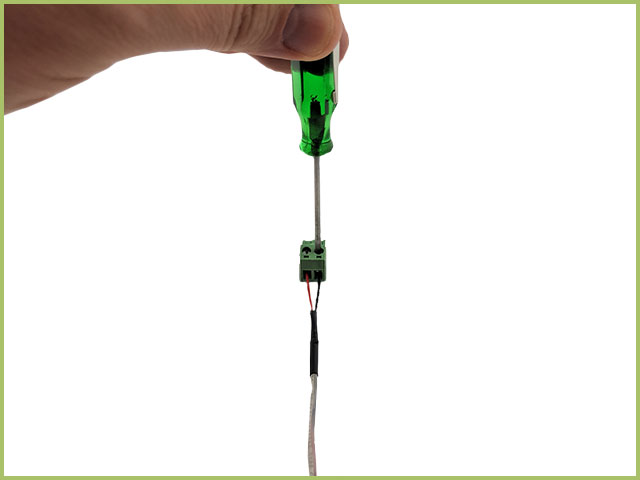
Figure 6. Connection of Cable to Current Version TTL Switch Block Connector
3.1.2Legacy Version TTL Switch Setup
The green block on the Pine Research potentiostat contains three signals, signal (0 - 10 V), ground (DC common), and a Rotator Enable Signal (not used with stirring). The block connector wire assembly breaks out the signal and ground lines from the Pine Research potentiostat and terminates them in wires, which are connected directly to the TTL Enabled AC Switch as shown (see Figure 7).
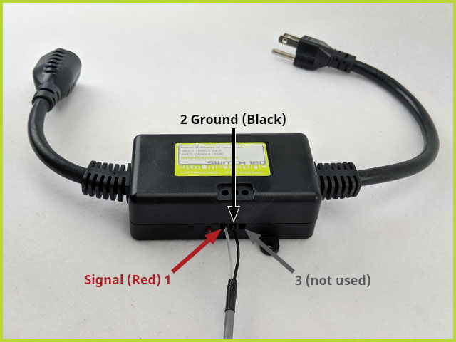
Figure 7. TTL Enabled AC Switch with Labeled Ports
There are three positions to receive a wire in the switch. From left to right, as shown in Figure 7, the positions are for signal, ground, and other (not used). The red wire should be installed in the left-most position and the black wire should be installed in the center position. The right-most position is not used in this application. To install, use a slim flat screwdriver to loosen the clamp for the left and middle positions. Slide the wire into the appropriate position. Hold in place while screwing down the connector (see Figure 8).
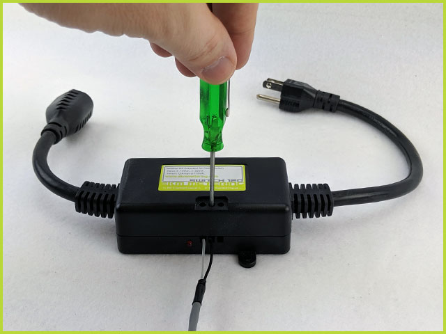
Figure 8. Securing wire in AC Switch with Screwdriver
3.2Step 2 - Connect Block Connector Wire to Potentiostat
Once the Block Connector Wire is connected to the TTL Switch, the other end with green block connector should be connected to the potentiostat. In the figure below, a WaveNow potentiostat
is used to demonstrate. First, remove the spare block from the connector (see Figure 9).
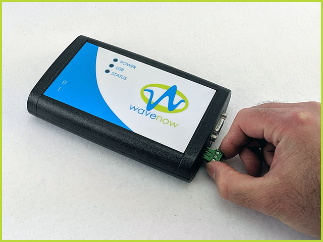
Figure 9. Remove Spare Block Connector from Potentiostat
Next, install the green block on the Wire Assembly into the green port on the potentiostat. The connector will only fit in one direction (see Figure 10 for Current Version TTL Switch and Figure 11 for Legacy Version TTL Switch).
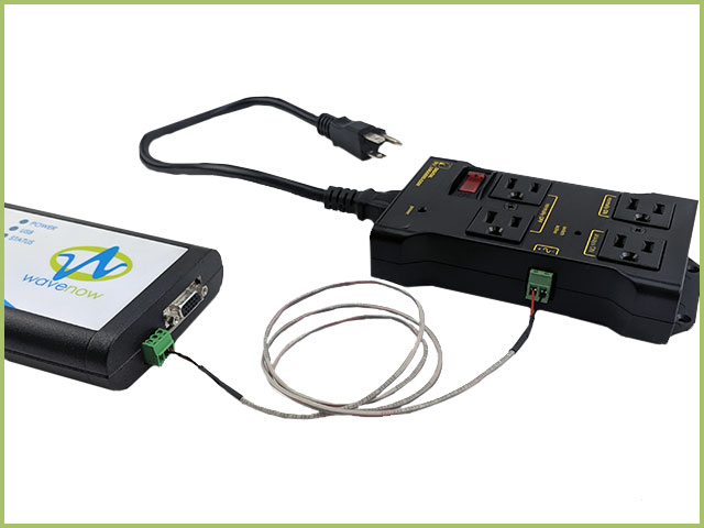
Figure 10. Connect Wire between Potentiostat and Current Version TTL Switch.
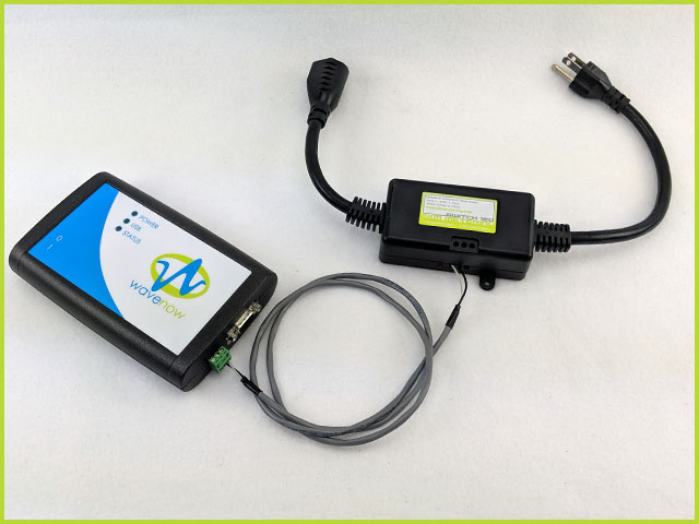
Figure 11. Connect Wire between Potentiostat and Legacy Version TTL Switch.
3.3Step 3 - Establish Stirring Rate
Stirring automation only automates ON/OFF of the stirrer during an electrochemical experiment. It does not control the stirring rate. This is strictly set by the knob on the stirrer. Before you continue with the setup, it is advised that the rotation rate be established. Plug the Stirrer power cord into the AC Mains. Place a stir bar on the plate and turn the knob until the stir bar reaches the desired rate, then unplug the stirrer from AC Mains and do not touch the rate knob (see Figure 12).
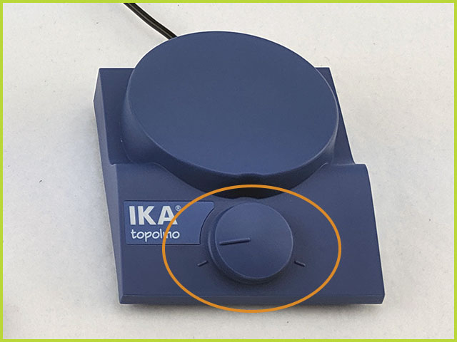
Figure 12. Set Stirring Rate with Knob
TIP: If stirring automation is part of a routine laboratory, we recommend marking the desirable position of the knob with some tape. This way, this step can be skipped and instead, the knob can be adjusted after the setup has completed. Remember, the automation merely turns the stirrer ON or OFF; it does not define or change stirring rate.
3.4Step 4 - Connect LowProfile Stirrer to TTL Switch
Once the previous steps have been completed, the next step is to connect the Stirrer to the appropriate power outlet. Doing so is different depending on which TTL Switch you have. Refer to the appropriate section below for either the Current Version TTL Switch or Legacy Version TTL Switch.
3.4.1Current Version TTL Switch
Do not connect the power cable for the LowProfile Stirrer directly into the AC Mains. Instead, attach the appropriate plug style adapter to the stirrer power cord and then plug the stirrer into one of two outlets on the Current Version TTL Switch labeled "normally OFF" (see Figure 13).
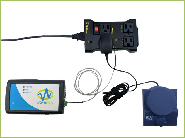
Figure 13. Full Assembly of Automated Stirring Kit with Current Version TTL Switch
Connect the potentiostat to power and to the computer via USB Cable. Connect the power plug from the TTL Switch into the AC Mains. Ensure the TTL Switch power switch (red/orange, top panel) has been turned on, as indicated by the switch being illuminated). Now the hardware is set up and all that remains is AfterMath software setup.
3.4.2Legacy Version TTL Switch
Do not connect the power cable for the LowProfile Stirrer directly into the AC Mains. Instead, attach the appropriate plug style adapter to the stirrer power cord and then plug the stirrer into the female connector on the TTL Switch (see Figure 14).
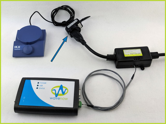
Figure 14. Connect Stirrer Power Cable to TTL Switch
Connect the potentiostat to power and to the computer via USB Cable. Connect the plug from the TTL Switch into the AC Mains. Now the hardware is set up and all that remains is AfterMath software setup.
4AfterMath Settings
There are three stripping methods available in AfterMath: Stripping Voltammetry (ASV),
Square Wave Stripping Voltammetry (SWSV),
and Differential Pulse Stripping Voltammetry (DPSV).
The educational laboratory exercise for determination of lead in tap water
uses DPSV and as such the figures below will use DPSV as an example.
Stirring automation is made possible by using the electrode rotator control port on Pine Research Potentiostats. Further, each step of a stripping voltammetry experiment in AfterMath includes the ability to automate stirring (turn the stirrer ON or OFF). AfterMath provides two options under "Stirring Method," which are "No Stirring" and "Use Rotator" (see Figure 10).
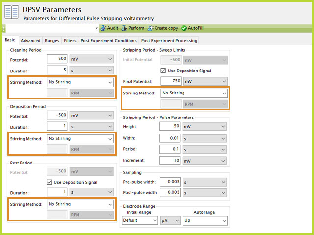
Figure 10. Differential Pulse Stripping Voltammetry (DPSV) Stirring Control Options Highlighted
To enable automation within AfterMath, select "Use Rotator" and enter 5000 RPM into the box below the "Use Rotator" selection. Be advised, 5000 RPM is NOT the stirring rate of the LowProfile stirrer. 5000 RPM is equivalent to a 5 V output from the green block, as the rotator control port being used is set to the ratio
Delivering +5V to the TTL Switch closes the circuit and allows power to the stirrer. The TTL Switch indicates a closed path by illuminating a red LED near where the Connector Wire Assembly is connected to the brick. When the LED is illuminated red, the stirrer has power, and it will stir at the rate as defined by the position of the stirrer knob. You will hear a slight click when the relay in the brick is enabled and disabled, as a result of the potentiostat outputting +5 V as defined in AfterMath (see Figure 11).
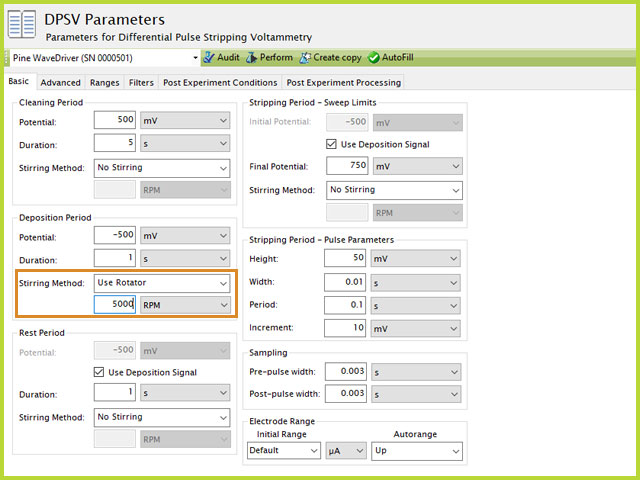
Figure 11. Enabling Stirring Automation in DPSV (AfterMath) with Rotator Controls
NOTE: The Stirring rate is set by the knob on the front of the stirrer. In no way does the automation control the rotation rate. Automation simply turns the stirrer ON or OFF at times associated with the stripping voltammetry experiment.


 EChem in a Box - Stirring Automation Pack
designed to complement EChem in a Box,
EChem in a Box - Stirring Automation Pack
designed to complement EChem in a Box,
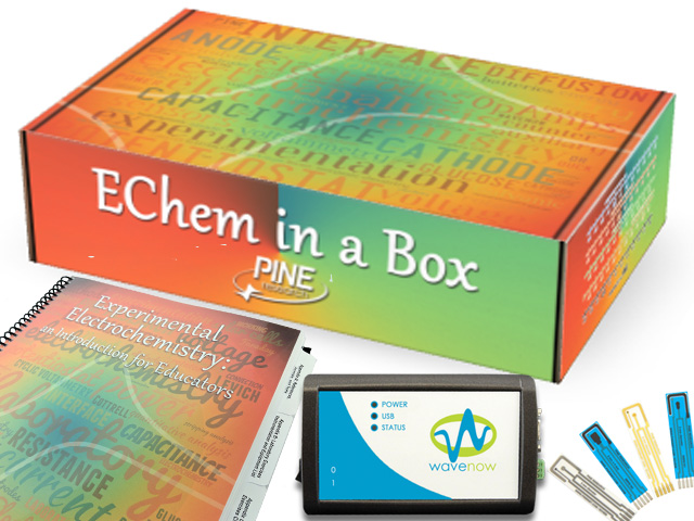 Standard EChem-in-a-Box Bundle
is useful for electrochemical methods that utilize stirring. For example, EChem in a Box includes an educational laboratory exercise for determination of lead in tap water,
Standard EChem-in-a-Box Bundle
is useful for electrochemical methods that utilize stirring. For example, EChem in a Box includes an educational laboratory exercise for determination of lead in tap water,
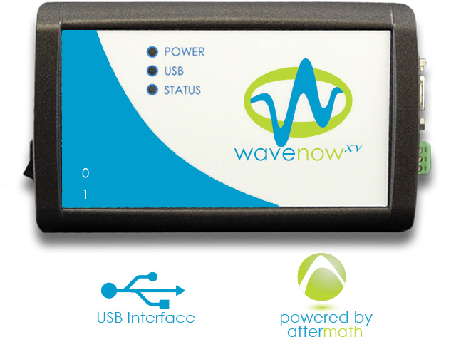 WaveNowXV Potentiostat Bundles
(or WaveDriver) potentiostat.
WaveNowXV Potentiostat Bundles
(or WaveDriver) potentiostat.
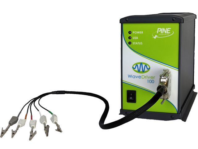 WaveDriver 100 EIS Potentiostat Basic Bundle
 Screen-Printed Electrode Large Volume Cell
(see Figure 2).
Screen-Printed Electrode Large Volume Cell
(see Figure 2). Classic WaveNow Potentiostat
is used to demonstrate. First, remove the spare block from the connector (see Figure 9).
Classic WaveNow Potentiostat
is used to demonstrate. First, remove the spare block from the connector (see Figure 9).