


General Electrochemistry
Back to General Electrochemistry Back to Applications Back to Knowledgebase HomeTroubleshooting Noise in an Electrochemical System with a Rotator
Last Updated: 12/30/21 by Alex Peroff
1Overview
Electrical noise is a common problem for researchers working with rotating electrodes. The following document details frequent noise sources and the steps to take to reduce noise in an electrochemical rotator system. Unfortunately, noise is often difficult to trace and eliminate since it can originate from many different sources. Therefore, even after implementing all of the steps detailed here, noise may still remain because of additional factors, such as lab infrastructure or interference from other instruments. In cases that the noise cannot be reduced to an acceptable level, the ultimate step may be to enclose the rotator system in a Faraday cage.
2Common Sources of Electrochemical Noise
2.1Reference Electrode
In order for a potentiostat to function properly, there must be adequate ionic conductivity between the electrolyte and the reference electrode. Otherwise, the potentiostat may measure a noisy signal. For proper ionic conductivity, the reference electrode must 1) maintain good contact with the sample electrolyte in an electrochemical cell; and 2) have a low impedance connection.
2.1.1Proper Electrolyte Contact
Good ionic conductivity through the reference electrode requires that there are electrolytes present both inside and outside of the frit compartment. Often, poor contact is caused by a gas bubble trapped near the reference electrode frit. The bubble disrupts ionic conductivity between the reference electrode’s internal electrolyte and the outside sample electrolyte, thereby creating high impedance and noise. Bubbles inside the fritted tube are most commonly introduced by the pipetting tool used to place electrolyte within the tube. Bubbles on the exterior of the frit form when the reference electrode is inserted into the electrolyte too quickly or too vertically. They can also form if there is a small recess at the bottom of the reference electrode tip. To fix this problem, either carefully slide the reference electrode in and out of solution at an angle until the bubble is removed, or use a pipette to fill the recess before inserting the reference electrode into the cell.
2.1.2Maintaining a Low Impedance Connection
High impedance may be encountered when the potentiostat has a poor connection to the reference electrode, such as a rusty alligator clip or a clogged frit. In addition, solutions with low-ionic concentrations or consisting of non-aqueous solvents often have high intrinsic solution impedance. Though both of these causes of high impedance may be present, the most common cause is a clogged frit, which restricts the ionic conductivity between the inner chamber of the reference electrode and the sample electrolyte.
If you suspect that a clogged frit is the problem, you can repeat your experiments with a known, good reference, such as a laboratory’s master reference electrode.
 Reference Electrode Storage and Master Reference Electrodes
If such a lab reference is not available, then a homemade frit-less Ag/AgCl reference electrode can be constructed to avoid issues commonly experienced by fritted glass reference electrodes. To construct a frit-less Ag/AgCl reference electrode, insert a platinum wire and a silver wire (typically 0.5 to 2 mm in diameter) into a 1.0 M KCl solution. Connect the platinum wire to the negative terminal and the silver wire to the positive terminal of a 1.5 V battery. Maintain this electrode configuration for about 60 sec. Alternatively, a potentiostat can be used for this purpose. The silver wire will be connected to both the working and the working sense leads of a cell cable. The platinum wire should be connected to both the counter and reference leads of the cell cable. Finally, set up an electrolysis (chronoamperometry) experiment with an applied potential of 1.5 V for 60 sec. During the electrolysis, solid silver chloride is deposited on the silver wire, forming an Ag/AgCl wire. The freshly-prepared Ag/AgCl wire can be placed straight into a 100 mM KCl electrolyte with no further preparation to test for noise in the electrochemical system. If the Ag/AgCl wire electrode eliminates the noise, the original reference electrode is likely defective and needs to be replaced.
Reference Electrode Storage and Master Reference Electrodes
If such a lab reference is not available, then a homemade frit-less Ag/AgCl reference electrode can be constructed to avoid issues commonly experienced by fritted glass reference electrodes. To construct a frit-less Ag/AgCl reference electrode, insert a platinum wire and a silver wire (typically 0.5 to 2 mm in diameter) into a 1.0 M KCl solution. Connect the platinum wire to the negative terminal and the silver wire to the positive terminal of a 1.5 V battery. Maintain this electrode configuration for about 60 sec. Alternatively, a potentiostat can be used for this purpose. The silver wire will be connected to both the working and the working sense leads of a cell cable. The platinum wire should be connected to both the counter and reference leads of the cell cable. Finally, set up an electrolysis (chronoamperometry) experiment with an applied potential of 1.5 V for 60 sec. During the electrolysis, solid silver chloride is deposited on the silver wire, forming an Ag/AgCl wire. The freshly-prepared Ag/AgCl wire can be placed straight into a 100 mM KCl electrolyte with no further preparation to test for noise in the electrochemical system. If the Ag/AgCl wire electrode eliminates the noise, the original reference electrode is likely defective and needs to be replaced.
2.2Cable Shielding and Length
Environmental noise can interfere with an electrochemical system through the cable that links the potentiostat to the electrochemical cell. To reduce noise that arises through the cable, ensure that the cable is as short as possible and/or that the cable is shielded. The Pine Research WaveNow
 WaveNowXV Potentiostat Bundles
and WaveDriver
WaveNowXV Potentiostat Bundles
and WaveDriver
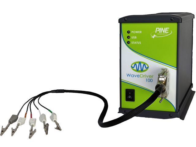 WaveDriver 100 EIS Potentiostat/Galvanostat
series potentiostats/bipotentiostats include a cell cable where all signal lines are individually-shielded. Additionally, the Pine Research WaveNow series potentiostats may be connected to a compact voltammetry cell through a mini-USB style cable that have all signal lines enclosed in a single shield.
WaveDriver 100 EIS Potentiostat/Galvanostat
series potentiostats/bipotentiostats include a cell cable where all signal lines are individually-shielded. Additionally, the Pine Research WaveNow series potentiostats may be connected to a compact voltammetry cell through a mini-USB style cable that have all signal lines enclosed in a single shield.
WaveNowXV Potentiostat Bundles
and WaveDriver
WaveDriver 100 EIS Potentiostat/Galvanostat
series potentiostats/bipotentiostats include a cell cable where all signal lines are individually-shielded. Additionally, the Pine Research WaveNow series potentiostats may be connected to a compact voltammetry cell through a mini-USB style cable that have all signal lines enclosed in a single shield.The discontinued Pine Research CBP bipotentiostat
AFCBP1 Bipotentiostat System User Guide
includes a shielded BNC cable for connecting to the reference electrode, but the working electrode(s) and counter electrode connections are unshielded. However, the default unshielded cables terminated with two banana plugs can be replaced with shielded BNC cables terminated with banana-plug-to-BNC (female) adapters. The shield or the ground line of a shielded cable for the working or the counter electrode can be connected to the chassis ground (a silver post) of the CBP bipotentiostat. However, the shield for the reference electrode should not be connected to any other conductor. For example, it should not be connected to the black banana socket (known as DC common), nor to the silver chassis ground of the CBP.
2.3Checking MSR Rotator Brush Contacts
The brush contacts to the Pine Research MSR rotator (part number AFMSRCE)
 AFMSRCE Rotator
shaft complete the conductive path for the electrical signals to and from the working electrodes in the electrochemical cell to the potentiostat. Electrical noise associated with the brush contacts can be of mechanical or electromagnetic origins. If the frequency of the observed noise is proportional to the rotator speed, then the noise is likely caused by mechanical factors. To inspect the rotator shaft and brush contacts, open the clam shell doors on the MSR rotator housing (see Figure 1).
AFMSRCE Rotator
shaft complete the conductive path for the electrical signals to and from the working electrodes in the electrochemical cell to the potentiostat. Electrical noise associated with the brush contacts can be of mechanical or electromagnetic origins. If the frequency of the observed noise is proportional to the rotator speed, then the noise is likely caused by mechanical factors. To inspect the rotator shaft and brush contacts, open the clam shell doors on the MSR rotator housing (see Figure 1).
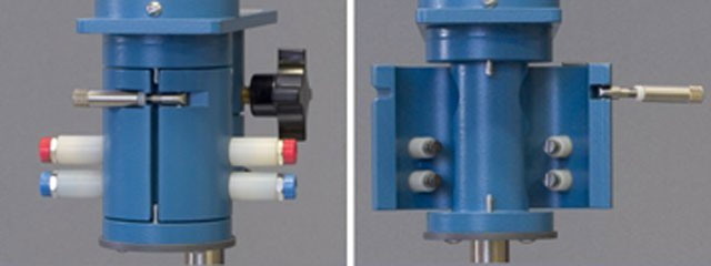
Figure 1. Rotator Housing Closed and Open to Visualize Brush Contacts
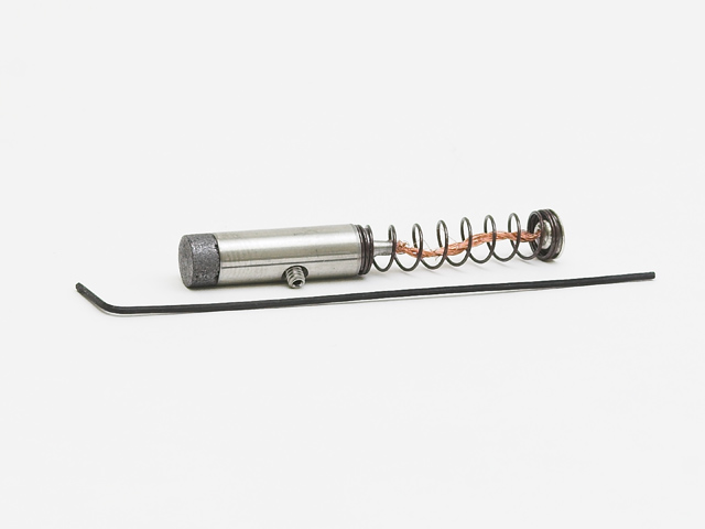
The rotator shaft surface should be very smooth and free of corrosion or defects. The surface of the brush contacts should be relatively flat and smooth when new, or curved with a groove to match the rotating shaft after use. The worn groove should align exactly with the rotator shaft. If the alignment is not perfect, do not try to realign the groove by rotating the brush contact. This method is inaccurate when done manually. A slightly misaligned groove with respect to the shaft can cause squeaking and vibrations, which contribute to the recorded noise. If misalignment already occurred, remove the brush contact and polish out the previous wear mark. Alternatively, the brush contact can be rotated with respect to the wear mark, so that the new wear mark will be perpendicular to the old one. Rotating the brush contact can eliminate the squeaking vibration.
The concave groove of a brush contact can be removed by polishing the end of a brush rod with a sandpaper. First, remove the brush rod assembly from the clam shell door by unscrewing it by hand. Then, take the brush rod out from its plastic housing, and polish the rod with a piece of sandpaper. The sandpaper should be secured to a flat surface, and the brush rod is perpendicular to this surface while being polished. To facilitate polishing with a defined perpendicular orientation, it may be advantageous to hold the brush rod in a fixture, such as the chuck of a drill press. Brush contact rods should be replaced when the carbon portion is about to be worn through. Replacement brush contacts can be purchased from Pine Research.
 MSR Rotator Brush Replacements
MSR Rotator Brush Replacements
2.4Grounding the Rotator Motor
Electrical noise associated with the brush contacts can also be the result of electromagnetic interference from either a nearby AC power supply or the rotator motor itself. For example, a rotator motor often emits magnetic field into its surrounding space, and any unshielded signal line around the motor will likely pick up this noise. The frequency of electromagnetic noise could be the line frequency (60 Hz) of the AC power supply or some other frequencies generated from the rotator motor. Motor noise can sometimes be reduced by grounding the rotator motor case.
First, to check for motor case grounding, use a multimeter to measure the resistance between the support post of the rotator and the chassis ground (the silver post) on the front panel of the rotator control unit. The resistance should be less than 1 Ω. Next, connect the chassis ground of the rotator control unit to the chassis ground of the potentiostat. For the WaveDriver series potentiostats, the chassis ground is a silver post (banana socket connector) on the back panel. The discontinued Pine Research CBP bipotentiostat chassis ground is a silver post on the front panel beneath the electrode connections. For WaveNow series potentiostats,
WaveNowXV Potentiostat Bundles
the chassis ground is shorted to the DC common by default, and the DC common can be accessed through the black banana plug of the WaveNow cell cable. Optionally, the chassis ground can be attached to an earth ground in the lab or to a large metal conductor such as the main metal post of the rotator (see Figure 2).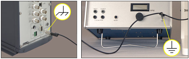
Figure 2. Ground Configuration Between MSR Rotator Control Unit and Potentiostat