


General Electrochemistry
Back to General Electrochemistry Back to Applications Back to Knowledgebase HomeReference Electrode Storage and Master Reference Electrodes
Last Updated: 6/9/23 by Neil Spinner
Download as PDF1Abstract
Pine Research offers various types of reference electrodes, many of which are suitable for use as master reference electrodes. To aid in the proper use of a master reference electrode, Pine Research offers two reference electrode storage vessels for our standard size reference electrodes. For low volume reference electrodes, we offer a separate reference electrode storage vessel. A master reference electrode with a well-known, stable equilibrium electrode potential is essential to test the performance of other active laboratory reference electrodes. Periodically testing all reference electrodes against the master reference electrode ensures that each reference electrode is working properly and in ideal condition. The article herein aims to introduce the purpose of reference and master reference electrodes, and then provides instructions on how to create, store, and test a master reference electrode.
2Background
2.1Reference Electrode
Many electrochemical techniques employ a three-electrode cell. The three electrodes (working, counter, and reference) each have a specific function during the electrode reaction; the working electrode facilitates electron transfer to the analyte of interest, the counter electrode maintains electroneutrality by participating in a reaction of opposite sign, and the reference electrode provides a stable potential against which the working electrode is poised. The stability of the reference electrode is crucial in all electrochemical experiments because individually measuring the absolute potential of each electrode is not possible. Rather, a known voltage is applied to the working electrode as a potential difference between the reference electrode and working electrode. Therefore, if the potential of the reference electrode varies, the measured potential applied to the working electrode also varies, skewing experimental results.
Obtaining a stable reference electrode potential is accomplished by utilizing a reversible redox pair at equilibrium. In practice, there are very few redox pairs that can act as reference redox pairs. The silver chloride reference electrode, whose shorthand electrochemical reaction is written as Ag|AgCl|KCl (saturated), is the most widely used reference electrode.
 Single Junction Silver Chloride Reference Electrode
It is as stable and reliable as the saturated calomel reference electrode SCE, whose shorthand electrochemical reaction is written as Hg|Hg2Cl2|KCl (saturated), but not as toxic.
Single Junction Silver Chloride Reference Electrode
It is as stable and reliable as the saturated calomel reference electrode SCE, whose shorthand electrochemical reaction is written as Hg|Hg2Cl2|KCl (saturated), but not as toxic.
 Zanello, P. Inorganic Electrochemistry: Theory, Practice, and Application The Royal Society of Chemistry: Cambridge, UK, 2003.
 Single Junction Calomel Reference Electrode
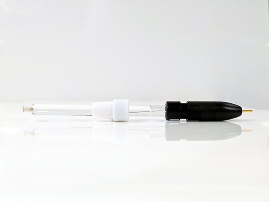
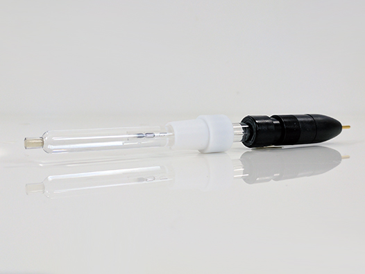
The silver/silver nitrate reference electrode, whose shorthand electrochemical reaction is written as Ag|AgNO3 in CH3CN|frit, is often used as an alternative reference electrode for non-aqueous solutions.
Gritzner, G.; Kuta, J. Recommendations on reporting electrode potentials in nonaqueous solvents. Pure Appl. Chem., 1984, 56(4), 461-466.
Single Junction Calomel Reference Electrode
The silver/silver nitrate reference electrode, whose shorthand electrochemical reaction is written as Ag|AgNO3 in CH3CN|frit, is often used as an alternative reference electrode for non-aqueous solutions.
Gritzner, G.; Kuta, J. Recommendations on reporting electrode potentials in nonaqueous solvents. Pure Appl. Chem., 1984, 56(4), 461-466.
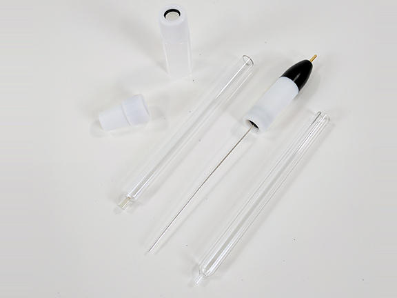 Non-Aqueous Standard Reference Electrode Kit
Single Junction Silver Chloride Reference Electrode
It is as stable and reliable as the saturated calomel reference electrode SCE, whose shorthand electrochemical reaction is written as Hg|Hg2Cl2|KCl (saturated), but not as toxic.
Single Junction Calomel Reference Electrode
The silver/silver nitrate reference electrode, whose shorthand electrochemical reaction is written as Ag|AgNO3 in CH3CN|frit, is often used as an alternative reference electrode for non-aqueous solutions.
Non-Aqueous Standard Reference Electrode Kit
With proper storage and cleaning techniques, most reference electrodes can be used repeatedly to save construction time and cost. However, if the reference electrode frit becomes clogged with analyte or electrolyte material, a significant rise in impedance across the frit can occur, leading to errors in the potential measured between the reference and working electrodes.
Zoski, C. G.; Leddy, J.; Bard, A. J.; Electrochemical Methods: Fundamentals and Applications (Student Solutions Manual), 2nd ed. John Wiley: New York, 2002.
Often, this error propagates from experiment to experiment until the reference electrode condition worsens to the point that data is visibly incorrect to the scientist.
2.2Master Reference Electrode
It is clear that only looking for inconsistencies in data to determine if a reference electrode is malfunctioning is a poor scientific method. Instead, electrochemists have developed a Master Reference Electrode to evaluate the stability of active laboratory reference electrodes. A master reference electrode is never used experimentally; rather, it is kept in pristine working order by storing it in an electrode filling solution. Thus, a master reference electrode serves as the ultimate reference electrode in the lab, to which all others of same construction can be compared.
By comparing the potential difference across two reference electrodes of the same type, scientists can determine the validity of an active laboratory reference electrode function. Due to the nature of a reference electrode, the reference potential is not directly measured. Rather, it is determined relative to the master. With both reference electrodes immersed in the same high concentration electrolyte filling solution (e.g., saturated KCl for the single junction Ag/AgCl reference electrode), the voltage difference (measured by open circuit potential) is ideally zero. ΔE = 0 mV indicates that the internal redox reaction of both the master and active laboratory reference electrodes are at the same equilibrium and that the ceramic frits are clear and porous as expected. A small shift in open circuit potential (-5 mV < ΔE < 5 mV) may be considered tolerable for the average experiment. The physical world often interferes with perfectly ideal reference electrode behavior; thus, the lab must determine their own acceptable deviation between active laboratory vs. master reference electrodes.
It is important to test all reference electrodes periodically with respect to the master electrode (if possible, before each experiment; see Section 4). Frequent comparison of active laboratory reference electrodes to the master reference electrode prevents error propagation discussed in Section 2.1. The master reference electrode must never be used in actual experiments to ensure its function and condition.
3Electrode Storage Preparation
3.1Products and Instrumentation
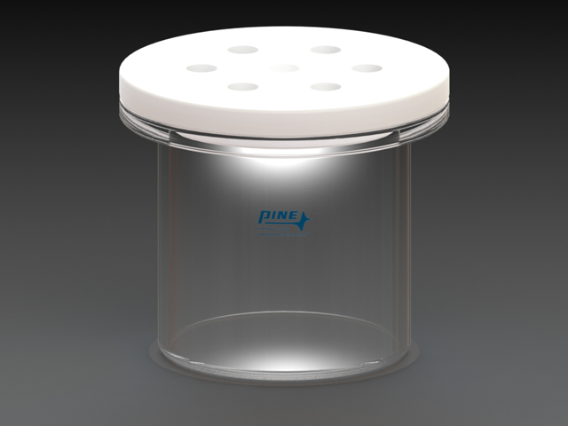
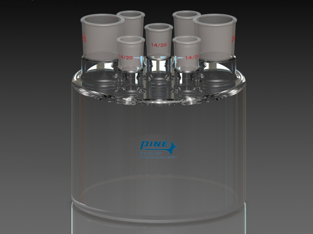
Pine Research offers three reference electrode storage vessels. AKREFHUT1 (see Figure 1)
 Reference Electrode Storage with Removable Lid
and AKREFHUT2 (see Figure 2)
Reference Electrode Storage with Removable Lid
and AKREFHUT2 (see Figure 2)
 Reference Electrode Storage
are equipped with multiple 14/20 ports to vertically-orient and mount a standard size reference electrode (9.5 mm OD), as well as a center 14/20 port to store and distinguish the master reference electrode. AKREFHUT1 features a removable polytetrafluoroethylene (PTFE) lid for solution addition while AKREFHUT2 features larger side ports (24/25) for solution addition and removal. A set of PTFE stoppers for all ports is included for both.
Reference Electrode Storage
are equipped with multiple 14/20 ports to vertically-orient and mount a standard size reference electrode (9.5 mm OD), as well as a center 14/20 port to store and distinguish the master reference electrode. AKREFHUT1 features a removable polytetrafluoroethylene (PTFE) lid for solution addition while AKREFHUT2 features larger side ports (24/25) for solution addition and removal. A set of PTFE stoppers for all ports is included for both.
Reference Electrode Storage with Removable Lid
and AKREFHUT2 (see Figure 2)
Reference Electrode Storage
are equipped with multiple 14/20 ports to vertically-orient and mount a standard size reference electrode (9.5 mm OD), as well as a center 14/20 port to store and distinguish the master reference electrode. AKREFHUT1 features a removable polytetrafluoroethylene (PTFE) lid for solution addition while AKREFHUT2 features larger side ports (24/25) for solution addition and removal. A set of PTFE stoppers for all ports is included for both.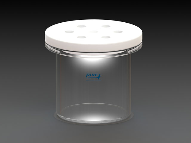
Figure 1. Reference Electrode Storage Vessel AKREFHUT1 with PTFE lid
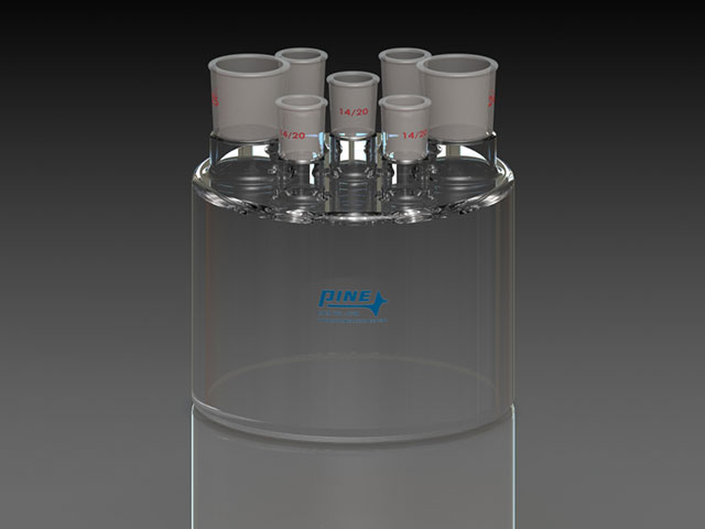
Figure 2. Reference Electrode Storage Vessel AKREFHUT2 with All Glass Taper Ports
AKREFHUT3
 Low Profile Reference Electrode Storage Vessel
is designed as a storage vessel for Low Profile reference electrodes with a 3.5 mm OD. The storage vessel is made with amberized glass to minimize potential photo-degradation of the reference electrode. The lid of the storage vessel has a rubber seal which prevents storage solution evaporation which can lead to precipitation of the saturated storage salt (see Figure 3).
Low Profile Reference Electrode Storage Vessel
is designed as a storage vessel for Low Profile reference electrodes with a 3.5 mm OD. The storage vessel is made with amberized glass to minimize potential photo-degradation of the reference electrode. The lid of the storage vessel has a rubber seal which prevents storage solution evaporation which can lead to precipitation of the saturated storage salt (see Figure 3).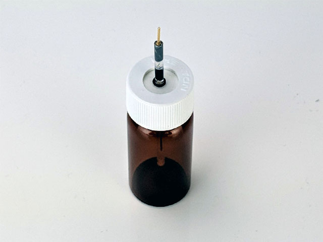
Figure 3. Low Profile Reference Storage Vessel AKREFHUT3
The reference electrode storage vessels are ideal for permanently storing the master reference electrode as well as storing active laboratory reference electrodes between experiments. Never allow a reference electrode filling solution to completely dry. Doing so may cause crystallization build up inside the electrode and within the frit. While soluble, these crystals may interfere with a reliable reference potential.
3.2Typical Reference Electrode Solutions
Reference electrodes are filled with an electrolyte solution whose composition depends on the redox reaction of interest within the electrode. For reference electrode storage, the same solution should be prepared and used in the storage vessels. Pine Research recommends that a separate storage vessel is used for each type of reference electrode, to minimize contamination across different electrolyte solutions. For the reference electrodes offered by Pine Research, a table has been provided to inform your electrode storage solution choices (see Table 1).
| Reference Electrode Name | Chemistry | Filling/Storage Solution |
| Silver/Silver Chloride (single junction) |  |
4M KCl (saturated) |
| Silver/Silver Chloride (double junction) | |
10% KNO3 |
| Saturated Calomel (SCE) |  |
4M KCl (saturated) |
| Mercury/Mercury Sulfate (single junction) |  |
~0.7 M K2SO4 (saturated) |
| Mercury/Mercury Sulfate (double junction) | |
~0.7 M K2SO4 (saturated) |
| Mercury/Mercury Oxide |  |
4.24 M KOH |
Table 1. Reference Electrode Types, Chemistry, and Filling/Storage Solutions
3.3Prepare the Master Reference Electrode Storage
To construct the master reference electrode storage electrolyte for AKREFHUT1 or AKREFHUT2, follow the instructions outlined below:
- Prepare 500 mL filling/storage solution. Refer to Table 1 for the appropriate filling/storage solution.
- Pour the electrolyte solution into the reference electrode storage vessel. A layer of electrolyte crystals may be visible at the bottom of the container for saturated solutions (see Figure 4).
- Ensure the master reference electrode is filled with filling solution. If needed, use a pipette to add electrolyte solution to the master electrode. Ensure that the master electrode tube is free from bubbles and does not contain electrolyte crystal deposits (see Figure 4).
- Place the master reference electrode in the electrolyte solution. Pine Research recommends storage of the master reference electrode in the center 14/20 port of the vessel.
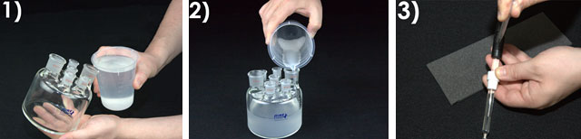
Figure 4. Steps to Prepare a Master Reference Electrode and Storage Vessel.
3.4Storage and Maintenance
The master reference electrode should be stored in filling/storage solution in a vessel like those available from Pine Research. These storage vessels should not be used for experimental use. The master reference electrode should never be used in conjunction with chemicals other than the electrolyte. Other reference electrodes utilizing the same electrolyte solution may be stored alongside the master reference electrode. Any ports or openings that are not used on the reference electrode storage container should be sealed with PTFE stoppers to prevent solution contamination and solvent evaporation (see Figure 3).
Periodically, the electrolyte solution should be refreshed. Prepare excess fresh, filling/storage solution in a separate container. Divide the filling/storage solution into two containers. Thoroughly rinse the outside and inside of the master reference electrode with the fresh filling/storage solution before filling it with fresh filling/storage solution. To prevent the frit from drying, rest the master reference electrode in one of the electrolyte solution containers. Repeat this procedure for any other reference electrodes stored in the reference electrode storage vessel. Pour the old electrolyte solution from the reference electrode storage container into a proper waste container and then rinse it with fresh electrolyte solution before filling it with fresh solution. Remount the master reference electrode and any other reference electrodes in the ports of the storage vessel. Seal off any open ports with PTFE stoppers.
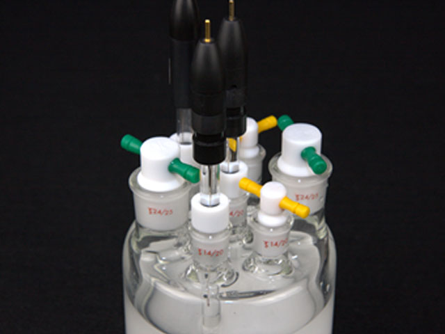
Figure 5. Example Reference Electrode Storage Container with Proper Sealing
4Testing Master Reference Electrodes
The master reference electrode can be used to test if another reference electrode is working properly. As discussed in Section 2.1, a properly-functioning reference electrode relies on a well-defined and constant equilibrium of redox pairs. This stable equilibrium gives rise to a constant potential. Therefore, if both the master reference electrode and test electrode are functioning properly, the voltage difference measured between them should be less than 5 mV because they are governed by the same reversible redox reaction at equilibrium and are in electrical contact by a high electrolyte concentration. This test can be performed easily with a multimeter or potentiostat. The following sections will describe how to use both techniques.
4.1Using a Multimeter
A multimeter has special electronic circuitry that enables it to measure several electronic signals, including voltage. To test the potential difference between a reference electrode and the master reference electrode with a multimeter, simply connect one lead of the multimeter to the active laboratory reference electrode under study and the other lead to the master reference electrode (see Figure 4). Ensure that the leads do not touch each other and that both electrodes are allowed to equilibrate in the same electrolyte solution for at least 10-15 minutes. Turn the selection dial on the multimeter to mV or V to measure the potential difference. The value should be less than 5 mV if the test reference electrode is working properly, relative to the master. If the value is changing rapidly on the display, allow the electrodes to equilibrate longer with the solution. If the potential difference is greater than 5 mV, the active laboratory reference electrode is likely suspect and should be reconditioned or discarded (refer to the reference electrode product information for refreshing instructions).
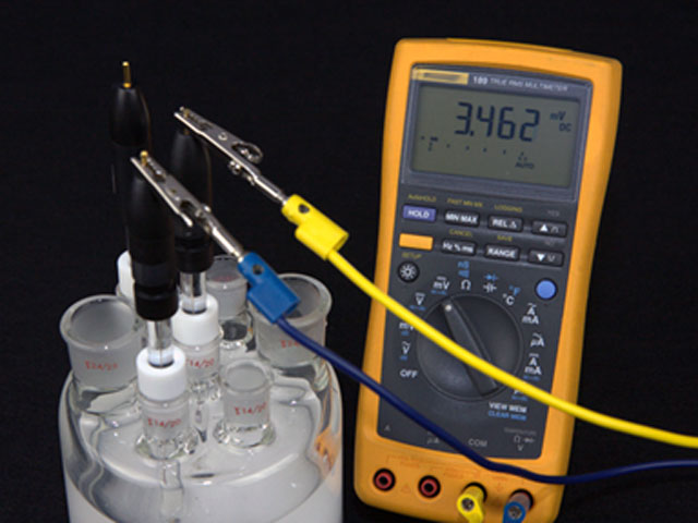
Figure 6. Reference Electrode Test with a Multimeter
4.2Using a Potentiostat
A potentiostat can perform an experiment called Open Circuit Potential (OCP)
 Open Circuit Potential (OCP)
that utilizes similar circuitry as the multimeter to find the potential difference between two electrodes. To test the potential difference between the test reference electrode and master reference electrode with a Pine Research potentiostat, short the counter (green lead) and reference (white lead) cell cable leads together and connect them to the master reference electrode by using an alligator clip. In addition, the working drive (red lead) and working sense (orange lead) cell cable leads should be shorted together and connected to the active laboratory reference electrode being tested (see Figure 7). Ensure that the leads do not touch and that both electrodes are allowed to equilibrate in the same electrolyte solution for at least 10-15 minutes. Open AfterMath software and select Open Circuit Potential from the Experiments menu. Click “I Feel Lucky” in the upper right corner to set default parameters for the experiment (see Figure 8). Click perform to run the experiment. The resulting chronopotentiogram should be relatively flat (without a slope) and have values between ±5 mV (see Figure 9).
Open Circuit Potential (OCP)
that utilizes similar circuitry as the multimeter to find the potential difference between two electrodes. To test the potential difference between the test reference electrode and master reference electrode with a Pine Research potentiostat, short the counter (green lead) and reference (white lead) cell cable leads together and connect them to the master reference electrode by using an alligator clip. In addition, the working drive (red lead) and working sense (orange lead) cell cable leads should be shorted together and connected to the active laboratory reference electrode being tested (see Figure 7). Ensure that the leads do not touch and that both electrodes are allowed to equilibrate in the same electrolyte solution for at least 10-15 minutes. Open AfterMath software and select Open Circuit Potential from the Experiments menu. Click “I Feel Lucky” in the upper right corner to set default parameters for the experiment (see Figure 8). Click perform to run the experiment. The resulting chronopotentiogram should be relatively flat (without a slope) and have values between ±5 mV (see Figure 9).
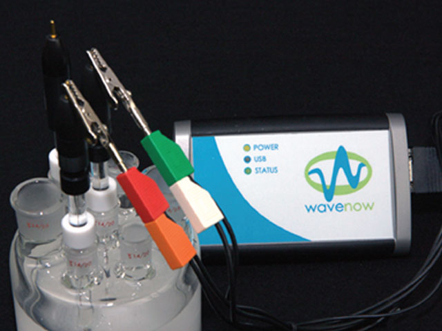
Figure 7. Reference Electrode Test with a Pine Research Potentiostat
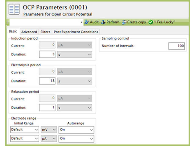
Figure 8. Open Circuit Potentiostat Parameters
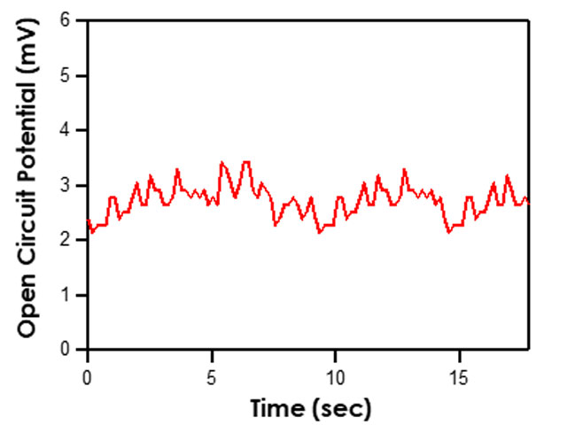
Figure 9. Typical Chronopotentiogram Acquired when Testing Reference Electrodes
5References
- Zanello, P. Inorganic Electrochemistry: Theory, Practice, and Application The Royal Society of Chemistry: Cambridge, UK, 2003.
- Gritzner, G.; Kuta, J. Recommendations on reporting electrode potentials in nonaqueous solvents. Pure Appl. Chem., 1984, 56(4), 461-466.
- Zoski, C. G.; Leddy, J.; Bard, A. J.; Electrochemical Methods: Fundamentals and Applications (Student Solutions Manual), 2nd ed. John Wiley: New York, 2002.