


Potentiostat Diagnostic Tests
Back to Potentiostat Diagnostic Tests Back to Applications Back to Knowledgebase HomeTesting Potentiostat Setup
Last Updated: 5/17/19 by Neil Spinner
1Testing Potentiostat Setup
This is often the first step involved in the initial system testing of a new Pine Research potentiostat (both WaveDriver and WaveNow models). The content in this post can also be found in the respective user guides for these potentiostats.
1.1Launch AfterMath Software
Launch AfterMath,
 Launching AfterMath
which should already be installed on the computer,
AfterMath Downloads
and log into AfterMath (see Figure 1). Click “OK” on the AfterMath Login dialog window to start the program.
Launching AfterMath
which should already be installed on the computer,
AfterMath Downloads
and log into AfterMath (see Figure 1). Click “OK” on the AfterMath Login dialog window to start the program.
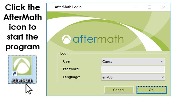
Figure 1. Initial Login Screen when Starting AfterMath
1.2Verify Instrument Status
Turn on the instrument using the main power switch and wait for the potentiostat to appear in the AfterMath instruments list. The instrument should appear along with its serial number under the “Instruments” node (see lower-left portion of the screenshot shown in Figure 2).
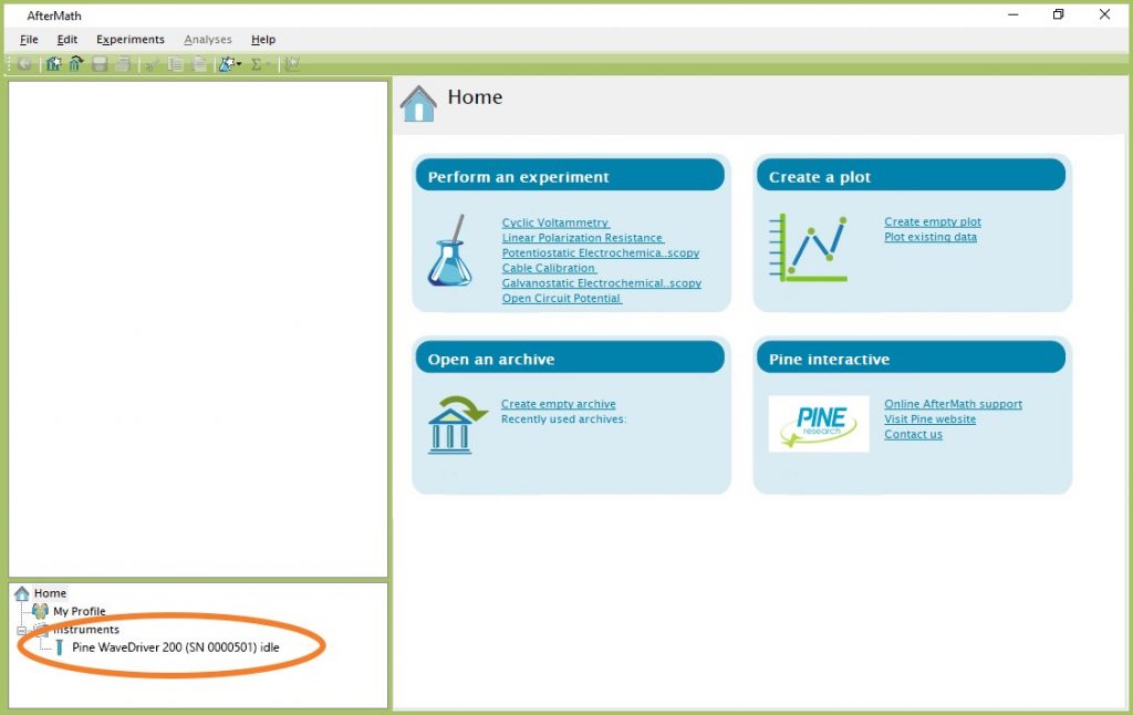
Figure 2. AfterMath Screenshot with Connected Instrument Circled
1.3Confirm Connections
Check the status LED on the front panel of the potentiostat. After about fifteen seconds, this LED should be green, indicating that the instrument is idle (see Figure 3). Also, the USB indicator light should flicker occasionally.
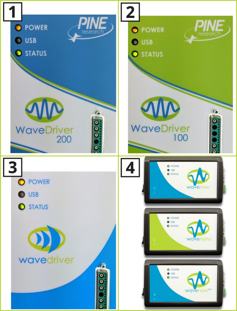
Figure 3. Indicator Lights on the Front Panel of (1) WaveDriver 200; (2) WaveDriver 100; (3) WaveDriver 40; and (4) WaveNow/WaveNano/WaveNowXV Potentiostats
1.4Review Instrument Status
Examine the instrument status display (see Figures 4 and 5). The information on the “Idle” tab may initially indicate that the cell is disconnected. If desired, the controls on this tab can be used to apply a known idle condition to the cell. In the example shown in Figure 4, the instrument (WaveDriver 200) is connected to the external cell, and both working electrodes are set to idle under potentiostatic control while applying 1.2 V to the first working electrode (K1) and 0.0 V to the second working electrode (K2). In the second example shown in Figure 5, the instrument (WaveDriver 100) has only one working electrode channel (K1), so the settings for the second working electrode (K2) are grayed out.
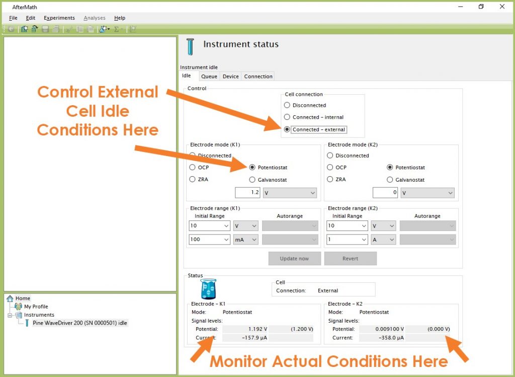
Figure 4. AfterMath Instrument Status Window showing External Cell Idle Conditions (Two Working Electrodes)
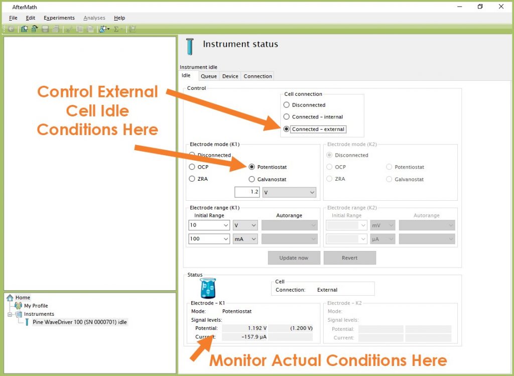
Figure 5. AfterMath Instrument Status Window showing External Cell Idle Conditions (One Working Electrode)