


1Required Tools
Gather the following tools prior to beginning the calibration:
- Digital laser tachometer (included in the MSR Rotation Rate Calibration Kit, AKMSRCAL
 MSR Rotation Rate Calibration Kit
)
MSR Rotation Rate Calibration Kit
) - Potentiometer adjustment tool (included in the MSR Rotation Rate Calibration Kit, AKMSRCAL
MSR Rotation Rate Calibration Kit
)
- Traceable, digital voltmeter (can use a potentiostat on site if not available)
- Traceable DC voltage source (at least 0-5 RPM) (can use a potentiostat on site if not available)
- Phillips screwdriver (included in the WaveVortex 10 Maintenance Toolkit, AK01WV10TK1
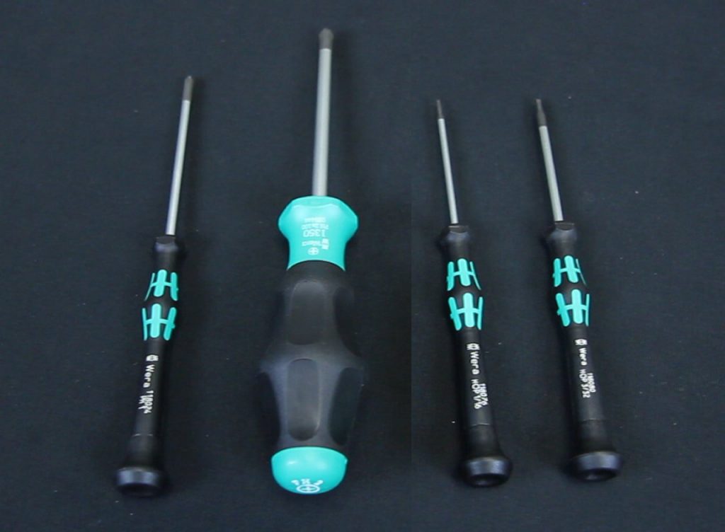 WaveVortex 10 Maintenance Toolkit
)
WaveVortex 10 Maintenance Toolkit
)
2Calibration Procedure
- Switch off power to the rotator and disconnect the power cord.
- With the power cord disconnected, remove the cover from the control unit (see Figure 1).
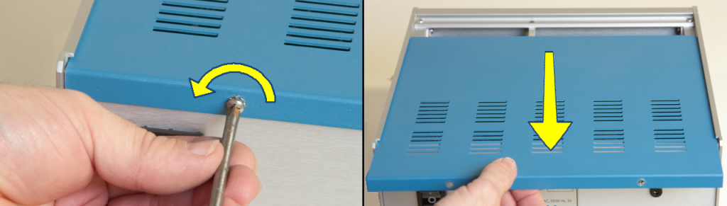
Figure 1. Removal of the MSR Rotator Control Unit Cover
- While the power is switched off, note the positions of the various trimmers located along the top of the main circuit board (see Figure 2). A trimmer adjustment tool (or a flathead screwdriver) is required to adjust these trimmers.
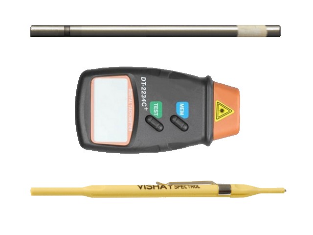
- While the power is switched off, install the tachometer target into the motor coupling on the motor unit. This target should be a metal rod with the appropriate diameter (1/4" or 6.35 mm), which is included with the MSR Rotation Rate Calibration Kit (AKMSRCAL
MSR Rotation Rate Calibration Kit
) (see Figure 3). Many tachometers require that a piece of reflective tape be attached to the end of the shaft, which has already been done to the calibration shaft included with the kit (see Figure 4).
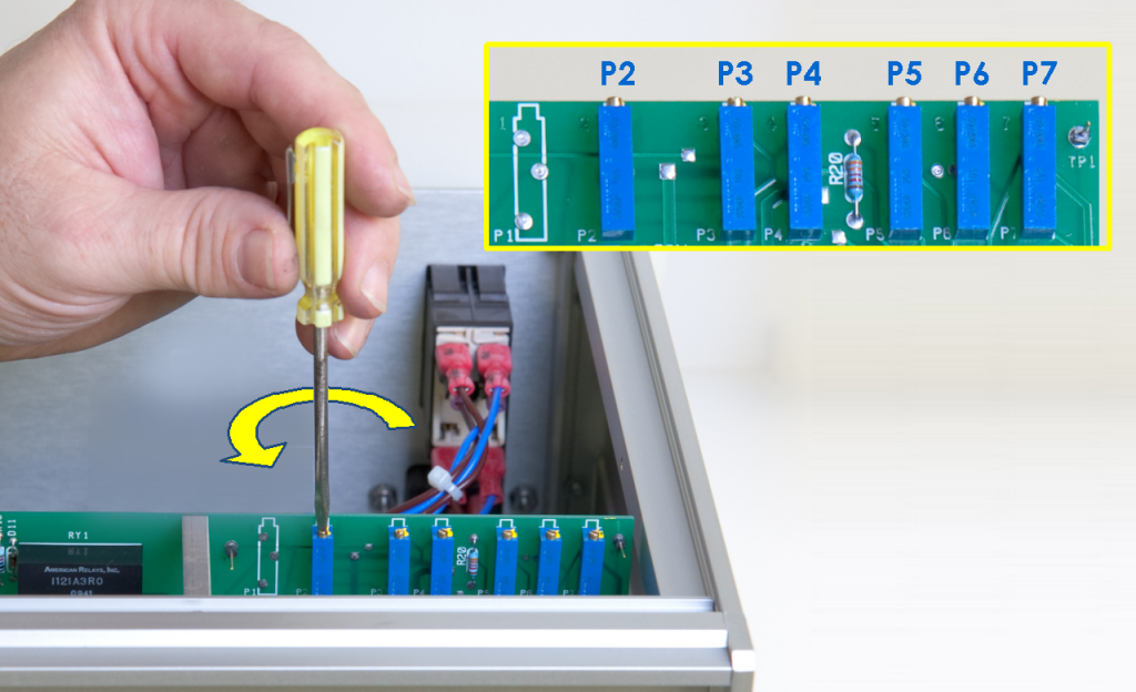
Figure 2. Location of the Trim Potentiometers on the MSR Rotator Control Unit Circuit Board
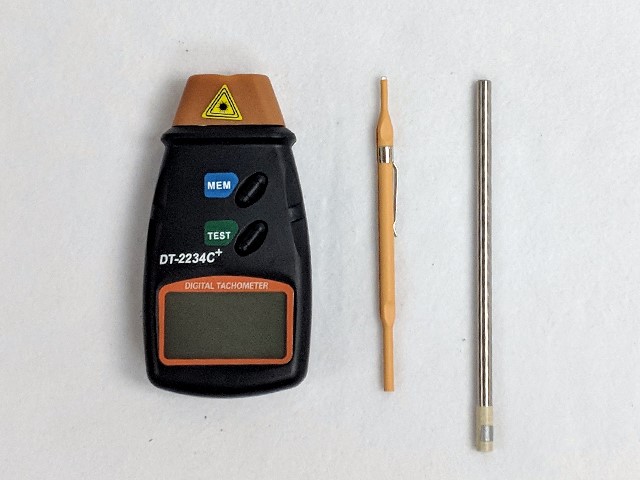
Figure 3. MSR Calibration Kit Tools
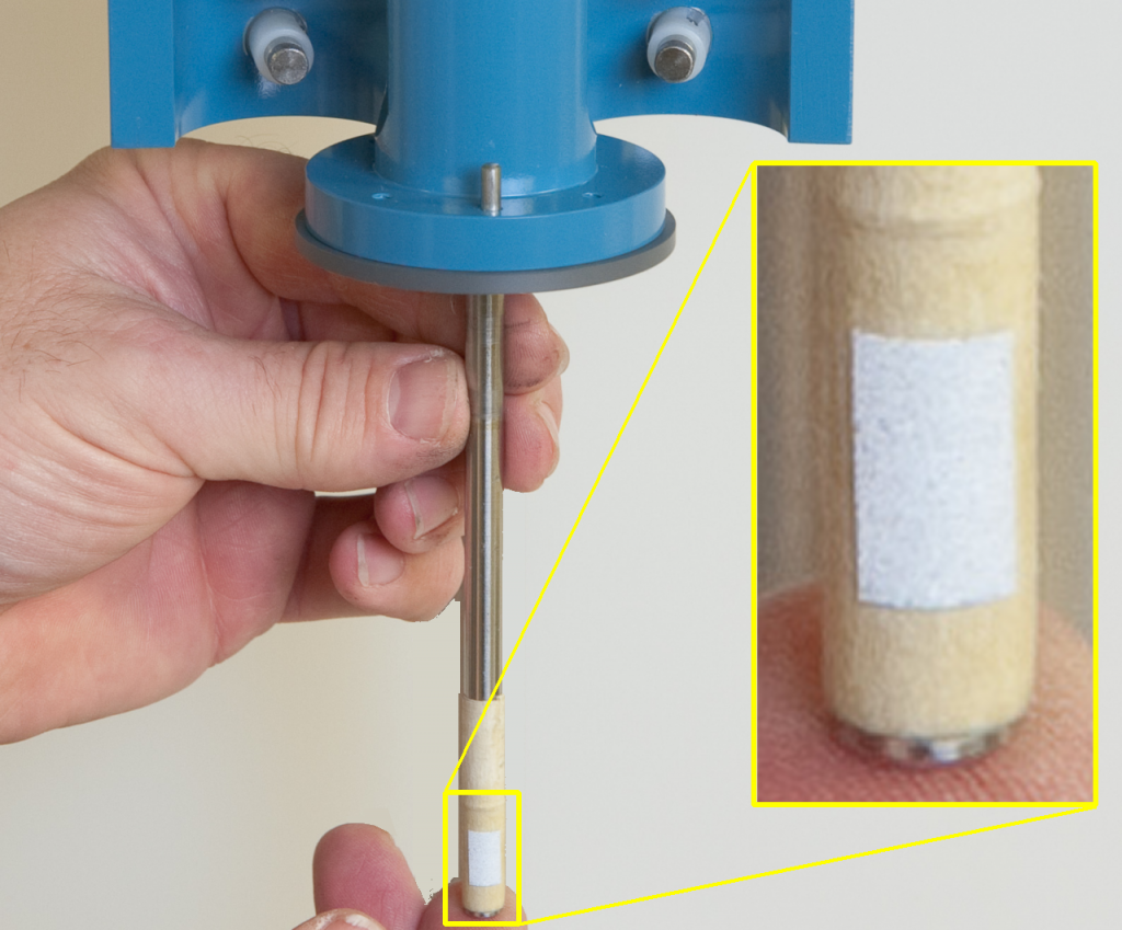
Figure 4. Installation of Calibration Shaft
- Turn the rotation rate knob fully counter-clockwise. This is the position which corresponds to a nearly zero rotation rate.
- Reconnect the power cord and carefully switch on the rotator.
- Using the tachometer to monitor the actual rotation rate, slowly adjust the rotation rate knob on the front panel until the tachometer indicates a rotation rate of approximately 2800 RPM.
- After the one hour waiting period, turn the rotation rate knob fully counter-clockwise. This is the position which corresponds to a nearly zero rotation rate.
- Locate test points TP2 and TP3 on the circuit board. These test points are accessible without the need to remove the circuit board from the control unit (see Figure 5).
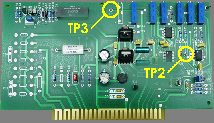
Figure 5. Location of Test Points on the MSR Rotator Control Unit Circuit Board
- Connect the black lead of the digital voltmeter to one of the two black banana jacks (DC common) on the front panel of the control unit. In the next several steps of the procedure, the red lead on the voltmeter is connected to various test points, but the black lead should remain connected to the DC Common jack on the front panel.
- Connect the red lead of the digital voltmeter to test point TP3 on the circuit board. Adjust trimmer P3 until the voltmeter reads 0.0000 VDC ± 0.0005 VDC.
- Connect the red lead of the digital voltmeter to test point TP2 on the circuit board. Adjust trimmer P2 until the voltmeter reads 0.0000 VDC ± 0.0005 VDC.
- Keep the red lead of the digital voltmeter connected to test point TP2 on the circuit board. Adjust trimmer P3 until the voltmeter reads approximately 0.0125 VDC. At this point, the motor should be rotating at a very slow rate. The direction of this slow rotation should be counterclockwise when looking down on the motor unit from above.
- Turn the rotation rate control knob very slowly until the motor comes to a complete stop. Adjust trimmer P7 until the rotation rate display on the front panel reads 0000 ± 1.
- Connect the red lead of the digital voltmeter to the OUTPUT signal jack on the front panel. Confirm that the signal level at this jack is 0.000 VDC ± 0.001 VDC.
- Using the tachometer to monitor the actual rotation rate, slowly adjust the rotation rate knob on the front panel until the tachometer indicates a rotation rate of 3000 RPM ± 1 RPM.
- While the shaft is rotating at 3000 RPM, adjust the trimmer P6 until the rotation rate display on the front panel of the control unit reads 3000 ± 1 RPM.
- Connect the red lead of the digital voltmeter to the OUTPUT signal jack on the front panel. Confirm that the signal level at this jack is 3.000 VDC ± 0.001 VDC.
- Slowly turn the rotation rate control knob counterclockwise until the motor comes to a complete stop.
- Connect a DC voltage source to the rotation rate INPUT signal jacks on the front panel of the control unit. The positive lead from the voltage source should be connected to the INPUT signal jack (gray banana jack), and the negative lead from the voltage source be connected to the DC Common (black banana jack).
- Determine the setting for the input rotation rate ratio (1,2, or 4 RPM/mV) by carefully examining the position of jumper JP2 on the circuit board (See Figure 8).
- Using the DC voltage source, apply 1.000 VDC ± 0.001 VDC to the rotation rate INPUT signal and observe the reading on the front panel display. The proper reading will depend upon the position of jumper JP2 as follows:
- If JP2 is set for 1 RPM/mV, the display should read 1000 RPM ± 1 RPM.
- If JP2 is set for 2 RPM/mV, the display should read 2000 RPM ± 1 RPM.
- If JP2 is set for 4 RPM/mV, the display should read 4000 RPM ± 1 RPM. - Adjust P5 until the rotation rate display on the front panel is within the ± 1 RPM tolerance. The optical tachometer should also indicate a rotation rate within this tolerance.
- Disconnect the voltage source from the INPUT jacks on the front panel.
- Verify the calibration at the several different rotation rates (suggested rates are 200, 500, 1000, 2000, and 5000 RPM). At each rotation rate, the rotation rate display on the front panel, the rotation rate indicated by the optical tachometer, and the rotation rate indicated at the OUTPUT jack on the front panel should all agree to within one percent (1.0 %). The readings noted during this step should be recorded in a log book or on a certification sheet.
- Switch off power to the rotator and disconnect the power cord.
- Use a small (5/64") hex key to loosen the hex screws in the motor coupling and remove the shaft from the rotator.
- Use the hex key to securely retighten the hex screws into the motor coupling.
- Close the clamshell doors on the brush chamber and secure the latch.
- Secure the enclosure around the rotator motor unit (see Figure 6).
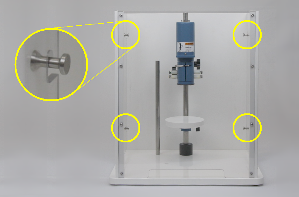
Figure 6. Secure Position of the MSR Rotator Enclosure
- Turn the rotation rate knob fully counter-clockwise. This is the position which corresponds to a nearly zero rotation rate.
- Reconnect the power cord and carefully switch on the rotator.
- Slowly turn the rotation rate control knob fully clockwise to the fastest rotation rate. The rotation rate display on the front panel of the control unit should read approximately 10050 RPM. Adjust trimmer P4 until the rotation rate display on the front panel of the control unit reads 10050 ± 10 RPM.
- Turn the rotation rate knob fully counter-clockwise. This is the position which corresponds to a nearly zero rotation rate.
- Switch off power to the rotator and disconnect the power cord.
- Replace the cover on the control unit (see Figure 7).
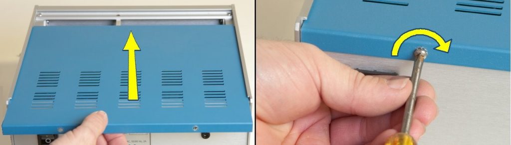
Figure 7. Installation of the MSR Control Unit Cover
3Verification Procedure
Following calibration (see Section 2. Calibration Procedure), verify the input to and output from the MSR Electrode Rotator.
Prior to verifying the calibration, it is necessary to verify the input ratio of the MSR Rotator. Determine the setting for the input rotation rate ratio (1,2,or 4 RPM/mV) by carefully examining the position of jumper JP2 on the circuit board (see Figure 8). From the production facility, Pine Research MSR Rotators are set to the 1 RPM/mV input ratio.
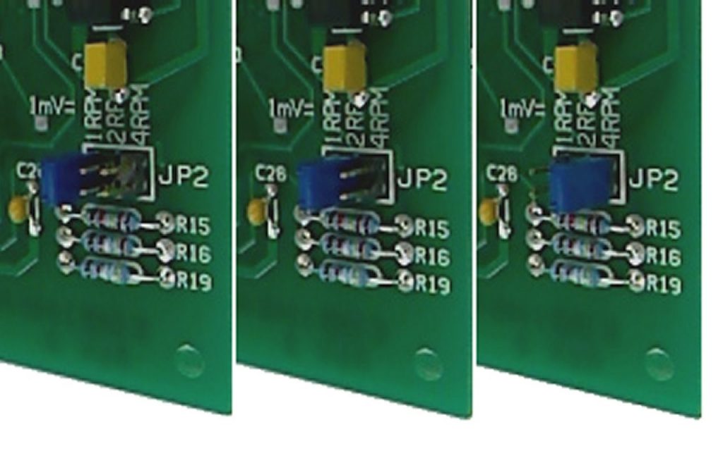
Figure 8. Input Ratio Setting Jumper on the MSR Rotator Control Unit Circuit Board
3.1Verification of Input Signal
- Using a DC voltage source, apply 1.000 ± 0.001 VDC to the rotation rate INPUT signal and observe the reading on the front panel display. The proper reading will depend upon the position of jumper JP2 as follows:
- If JP2 is set for 1 RPM/mV, the display should read 1000 ± 1 RPM.
- If JP2 is set for 2 RPM/mV, the display should read 2000 ± 1 RPM.
- If JP2 is set for 4 RPM/mV, the display should read 4000 ± 1 RPM.
- Record the tachometer reading and control unit display readings (see Table 1).
- Repeat steps 1-2 for a series of voltage inputs (see Table 1).
- Disconnect the voltage source from the INPUT jacks on the front panel.
| Input Signal (V) | Expected Rotation Rate (RPM) | Tachometer Reading (RPM) | Control Unit Display Reading (RPM) |
| 0.100 | 100 ± 2.0 | ||
| 0.200 | 200 ± 2.0 | ||
| 0.500 | 500 ± 2.0 | ||
| 1.000 | 1000 ± 10.0 |
Table 1. MSR Rotator Input Signal Verification
3.2Verification of Output Signal
Verify the calibration at the several different rotation rates.
- Prepare the MSR Rotator by connecting it to its power supply, adjusting the power switch to the on position, applying a piece of reflective tape to the shaft.
- Connect the voltage carrying lead (typically red lead for a digital voltmeter, or the Working/Working Sense leads of a potentiostat) to the OUTPUT port on the MSR Control Unit. Connect the ground/common lead (typically black lead for digital voltmeter, or the Counter/Reference leads of a potentiostat) to the black port on the MSR Control Unit.
- Set the rotation rate of the MSR Rotator by turning the knob to the desired rate (see Table 2).
- Record the tachometer reading and output voltage measurement.
- Repeat steps 3-4 for a series of voltage inputs (see Table 2).
| MSR Control Unit Display Reading (RPM) | Expected Rotation Rate (RPM) | Tachometer Reading (RPM) | Output Signal (V) |
| 100 | 100 ± 2.0 | ||
| 200 | 200 ± 2.0 | ||
| 500 | 500 ± 5.0 | ||
| 1000 | 1000 ± 10.0 | ||
| 2000 | 2000 ± 20.0 | ||
| 5000 | 5000 ± 50.0 |
Table 1. MSR Rotator Output Signal Verification
3.3Finalization
After completing calibration and verification tasks, turn the MSR Control unit power switch to the off position and disconnect the power supply. Remove the shaft with reflective tape. Use the screwdriver to secure the panel to the top of the control unit. Make final notations in a calibration record, as appropriate.