


Legacy Potentiostats
Back to Legacy Potentiostats Back to Legacy Product Support Back to Knowledgebase HomeAFCBP1 Filter Board
Last Updated: 4/30/19 by Neil Spinner
1Introduction
The AFCBP1 bipotentiostat signal filter board provides low-pass filters for both the excitation and response signals that travel between the interface board and the bipotentiostat through the interface cable. There are multiple jumpers on the filter board that are used to select the cutoff frequencies for the various low-pass filters. This article describes how to install a signal filter board inside a AFCBP1 bipotentiostat system, as well as how to change the jumper configuration for the filters. This board is available as an upgrade option for older AFCBP1 systems that do not already have an installed filter board. The part number for this board is AB01CBPF. A new filter board usually ships with a 1000 Hz cutoff frequency for excitation signals and a 10 Hz cutoff frequency for the response signals.
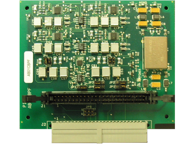
Figure 1. AFCBP1 Filter Board
2Board Installation
The installation process is broken up into four major steps below:
- Release the swing locks
- Disconnect the power cord from the bipotentiostat
- Remove the top cover from the bipotentiostat and locate the 50-pin connector on the main analog board
- The 50-pin connector is designated as “J10” and is labeled with the words “TO COMPUTER”
- Using both hands, carefully release the two “swing locks” by pushing outward and downward on both lock levers at the same time (see Figure 2). As the swing locks are released, the ribbon cable is pushed out of the connector
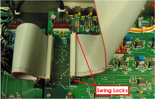
Figure 2. Release Swing Locks
- Examine the ribbon cable and take special notice of the location of the “key ridge” on the connector (see Figure 3)
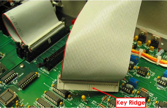
Figure 3. Identify Ridge Key
- Engage swing locks on connector “J1” (see Figure 4)
- Locate the connector designated as “J1” on the filter board
- Align the key ridge on the ribbon cable with the matching key slot on connector “J1” on the filter board
- Push the ribbon cable connector “J1” while applying even pressure to avoid bending any of the pins
- As the ribbon cable is pushed into the connector, the swing locks on connector “J1” should engage and click into place. It may be necessary to gently push on the lock levers to assist the locking mechanism
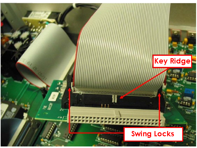
Figure 4. Engaging Swing Locks
- Finish the Installation (see Figure 5)
- Push connector “J2” on the filter board into connector “J10” on the main analog board
- Once again, pay close attention to the swing locks on connector “J10” and assure that they engage and click into place
- Replace the top cover on the bipotentiostat
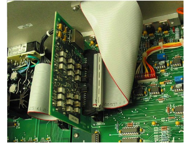
Figure 5. Final Installation of Filter Board for AFCBP1 Bipotentiostat
3Internal Filter Board Settings
There is a signal filter board installed inside the AFCBP1 bipotentiostat that filters the signals that travel through the interface cable. Both the excitation signals and the response signals are filtered using this board. Note that this board may not be present in some early model AFCBP1 bipotentiostats, but it may be obtained from Pine Research and installed in an existing AFCBP1 system.
CAUTION: If an internal filter board is installed inside the CBP bipotentiostat system, and the older PCI-6030E interface board is being used (also known as the PCI-MIO-16XE-10 interface board), there are limitations regarding the current and potential measurement ranges that must be taken into consideration. Be sure to read and understand the description of the limitations of this particular interface board.
 AFCBP1 Interface Boards
In addition, be sure to use AfterMath Version 1.2.4532 (or a more recent version)
AFCBP1 Interface Boards
In addition, be sure to use AfterMath Version 1.2.4532 (or a more recent version)
 AfterMath Downloads
when working with this combination of boards.
AfterMath Downloads
when working with this combination of boards.
3.1Excitation Signal Filters
The waveforms applied by the interface board to the bipotentiostat are called the excitation signals. There is one excitation signal for each of the two working electrodes (K1 and K2). These excitation signals are generated by the interface board (which is installed in a Windows-based personal computer), and the signals travel through the interface cable to a connector on the back panel of the bipotentiostat. After passing through the back panel, these signals may be filtered to remove any digital noise from the computer that may have traveled through the interface cable.
There are three filtering options available for each excitation signal. One option is to allow the signal to pass through without any filtering. The other two options are low-pass filters with either a 10 Hz or 1 kHz cutoff frequency. The excitation signal filters for each signal (K1 and K2) may be set independently; however, it is common practice to apply the same amount of filtering to both signals.
The table below list the jumper settings for the filtering options available for the K1 and K2 excitation signals. The factory default settings use the 1 kHz filters for both K1 and K2.
| Electrode Channel | 1 kHz Filter | 10 kHz Filter | No Filter |
| K1 Electrode Excitation Signal | JP6- A and B open JP7- pins 1 and 2 closed |
JP6- A and B closed JP7- pins 1 and 2 closed |
JP7- pins 2 and 3 closed |
| K2 Electrode Excitation Signal | JP8- A and B open | JP8- A and B closed JP9- pins 1 and 2 closed |
JP9- pins 2 and 3 closed |
Table 1. Jumper Configurations for Electrode Excitation Signal Filters
The three figures below (see Figures 6 - 8) show the proper configurations for the jumpers that control filtering of the excitation signals:
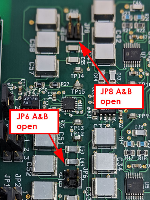
Figure 6. Example of Jumpers in Open Position
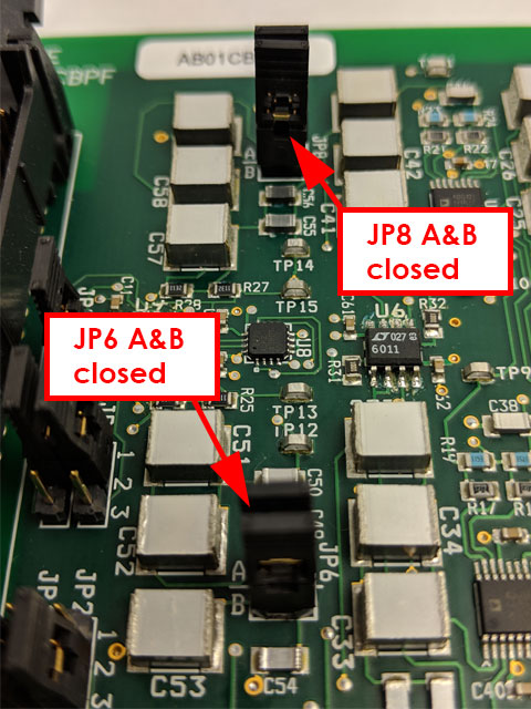
Figure 7. Example of Jumpers in Closed Position
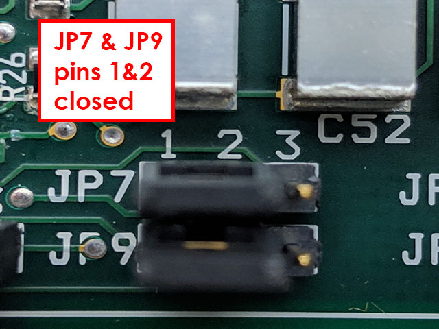
Figure 8. Example of Closing Two Pins Together
3.2Response Filters
The current and potential signals measured at both working electrodes are the four principle response signals that travel from the bipotentiostat back to the interface board through the interface cable. All four of these signals (E1, I1, E2, and I2) are filtered using low-pass filters. The cutoff frequency for all four low-pass filters is adjusted using jumpers JP1 and JP2 on the signal filter board. There are four different cutoff frequencies available (1, 10, 100, and 1 kHz, see Figure 9). The frequency setting applies to all four signals (i.e., it is not possible to set the frequency individually for each response signal). The factory default settings use the 10 Hz filters for both K1 and K2.
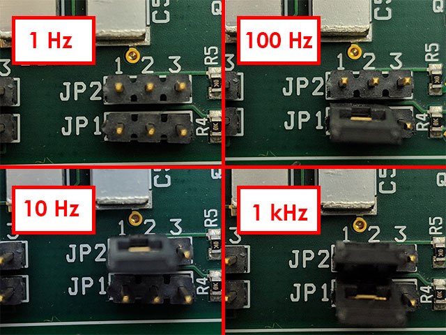
Figure 9. Response Filter Settings for AFCBP1 Bipotentiostat
| 1 Hz | 10 Hz | 100 Hz | 1 kHz |
| JP1 – all pins open JP2 – all pins open |
JP1 – all pins open JP2 – pins 1 and 2 closed |
JP1 – pins 1 and 2 closed JP2 – all pins open |
JP1 – pins 1 and 2 closed JP2 – pins 1 and 2 closed |
Table 2. Jumper Configurations for Response Filters
3.3External Software Control
The choice of cutoff frequency for the response signals may be placed under external software control (via the interface board) by setting the jumpers as shown in the figure below (see Figure 10). This option is only available when using AfterMath (version 1.3 or higher)
AfterMath Downloads
in conjunction with an M Series interface board (such as the PCI-6251).
AFCBP1 Interface Boards
Contact Pine Research
Contact
for further details.
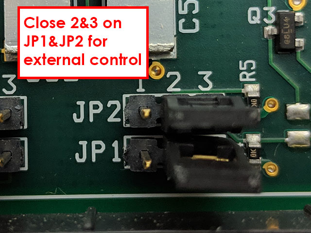
Figure 10. Jumper Configuration for External Software Control of Response Filter (JP1 and JP2 Pins 2 and 3 Closed)
3.4Ground Reference Selection
3.4.1Excitation Signals
The excitation signals generated by the interface board are (by default) referenced with respect to the analog output ground (AOGND) located on the interface board itself. It is possible to use a jumper on the filter board to cause the excitation signals to be referenced with respect to the local ground for the AFCBP1 bipotentiostat instead. This latter choice is not recommended at this time. Contact Pine Research
Contact
for further details.
| Interface Board Ground (AOGND) | CBP Local Ground (DC Common) |
| JP3 – pins 2 and 3 closed | JP3 – pins 1 and 2 closed |
Table 3. Jumper Settings for Excitation Signal Ground Reference
3.4.2Response Signals
It is possible to connect the response signal ground reference from the AFCBP1 bipotentiostat (i.e., the DC Common) to any of three different ground references on the interface board. By default, no such connections are made. However, a jumper on the filter board can be used to connect the DC Common to one of three lines on the interface board (AOGND, AISENSE, or AIGND). Such connections are not recommended at this time. Contact Pine Research
Contact
for further details.
| No connection (default) | AOGND | AISENSE | AIGND |
| JP5 – all pins open | JP5 – pins 1 and 2 closed | JP5 – pins 3 and 4 closed | JP5 – pins 5 and 6 closed |
Table 4. Jumper Settings for Response Signal Ground Reference
4Other Methods to Minimize Noise
4.1Ground Connections
When working with the AFCBP1 bipotentiostat system, it is very important to make certain that all parts of the system are properly grounded. The computer system, the monitor, and the bipotentiostat should all be connected to the same grounded power source (i.e., do not connect the computer and the bipotentiostat to different power circuits).
The metal chassis of the bipotentiostat is connected to the earth ground via the third prong on the power cord. The front panel of the bipotentiostat has a convenient binding post (in the lower right corner) that can be used to make additional earth grounding connections as needed. Typically, any metal object located near the electrochemical cell (such as a rotating disk electrode, a clamp holding the cell, or a Faraday cage around the cell) should also be connected to the earth ground.
4.2Cell Cable Shielding
The various cables that connect the bipotentiostat to the electrochemical cell should be of the shielded (coaxial) type whenever possible. These cell cables should be routed well away from any power cords, network cables, or video monitors, all of which are considerable sources of electrical noise.
The cable that connects to the reference electrode must be of the shielded coaxial type. The shield of this cable is driven by the bipotentiostat to the same potential as the reference electrode. Thus, the shield line on the reference electrode cable should never be connected to ground.
4.3Feedback Attenuation Knob
An analog bipotentiostat circuit is based on a set of feedback loops built from operational amplifiers. In any such feedback system, there is a trade-off between the response time of the system and the stability of the system. To increase the stability of the system, the response time of the system can be intentionally attenuated (i.e., slowed or damped). Conversely, adjusting the system to be more responsive may make the system prone to oscillations caused by constructive feedback and amplification of small noise signals.
When a potentiostat system is connected to a particular electrochemical cell, it is often necessary to tune the responsiveness of the instrument to match the cell geometry and type experiment being performed. In general, it is desirable to tune the potentiostat to the minimum amount of feedback attenuation required to guarantee stable operation. Finding the proper amount of attenuation is often a trial-and-error process.
On the back panel of the AFCBP1 bipotentiostat, there is a knob that can be used to adjust the amount of attenuation in the analog feedback circuits (see Figure 11). This knob has four settings marked 0, 1, 2, and 3. The lowest setting (0) represents the least amount of attenuation (fastest instrument response time) while the highest setting (3) introduces a great deal of attenuation into the circuit (slow instrument response time).
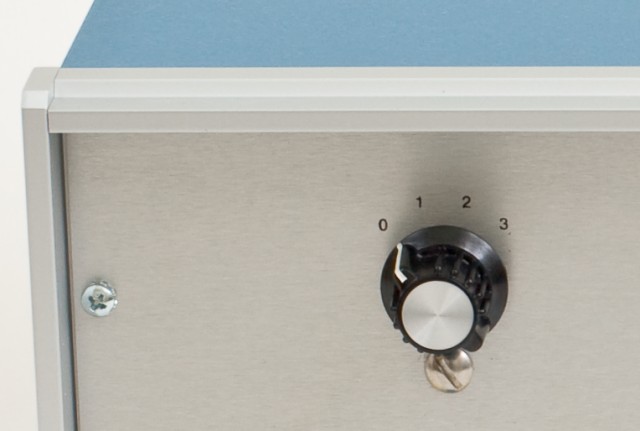
Figure 11. AFCBP1 Feedback Attenuation Knob
When possible, the instrument should be operated with the feedback attenuation knob in position “0” or “1”. This allows the instrument to remain fairly responsive to sudden changes in signal levels without significant distortion.
In certain slow, steady-state experiments (such as rotating disk voltammetry and rotating ring-disk voltammetry), the attenuation knob can be adjusted to position “2” to provide even greater stability. Because such steady state experiments do not typically generate signals that change rapidly, the extra damping associated with position “2” is not a major concern.
Position “3” is not recommended except for those cases where signals remain constant over very long periods of time (e.g., very long-term electrolysis experiments).