


Autorange
Last Updated: 10/31/19 by Alex Peroff
1Introduction
Autorange is a special feature in AfterMath that will automatically switch the electrode range
 Electrode Range
during an experiment to prevent an overload error. This is particularly useful when performing experiments for the first time where the current or voltage magnitude is unknown. However, Autorange should mainly be used to determine the acceptable electrode range. For all subsequent experiments the user should use the smallest electrode range necessary to detect the measured signal.
Electrode Range
during an experiment to prevent an overload error. This is particularly useful when performing experiments for the first time where the current or voltage magnitude is unknown. However, Autorange should mainly be used to determine the acceptable electrode range. For all subsequent experiments the user should use the smallest electrode range necessary to detect the measured signal.
2Autorange troubleshooting
While Autorange is a useful tool when performing experiments, it can also be the cause of glitches and errors in your electrochemical data. The electrode range is determined by the selection of A/D converters,
Electrode Range
but is also determined by the choice of physical hardware in the potentiostat circuit. When the electrode range switches there is a physical switch in the hardware of the potentiostat. Depending on several experimental parameters, the time response of the switch can cause a glitch in your electrochemical data.
Cell and Circuit Switching
The following sections below describe time sensitive experimental parameters that might cause an Autorange error.
2.1Sample Rate
The sample rate determines how frequently the potentiostat is collecting data from your experiment. If the potentiostat is collecting data very quickly, (1 data point per μsec) you might observe a short glitch in the data as the potentiostat switches from one electrode range to the other. However, if you were performing a one hour long experiment, and only collected one data point every 30 seconds, you would not observe a glitch associated with switching electrode ranges.
2.2Scan Rate
For electrochemical techniques that sweep the potential of current as a function of time, fast scan rates can result in glitches when autorange is on. A typical scan rate for a technique such as cyclic voltammetry
Cyclic Voltammetry (CV)
is 100 mV/s. However, when fast scan rates such as 5 and 7 V/s are used in conjunction with Autorange, you can observe glitches in the cyclic voltammogram. Below is an example of a cyclic voltammogram of 1 mM acetaminophen in saline solution at 7 V/s, with Autorange on and off.
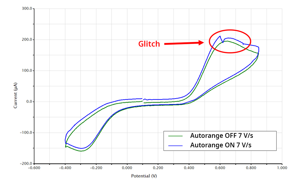
Figure 1. Cyclic voltammogram of 1 mM acetaminophen at 7 V/s with Autorange off (green) and Autorange on (blue). Glitch during forward scan is associated with autoranging at fast scan rates.
The data from the cyclic voltammogram above was taken using the Wave Now
 Classic WaveNow Potentiostat
which has four current ranges, ±10 μA, ±200 μA, ±5 mA, and ±100 mA. In figure 1 you'll notice that the glitch occurs right around the + 200 μA, which corresponds to a change in the current range. While this glitch is easy to observe in the cyclic voltammogram, you can see that more glitches occurred when viewing the applied vs measured potential waveform.
Classic WaveNow Potentiostat
which has four current ranges, ±10 μA, ±200 μA, ±5 mA, and ±100 mA. In figure 1 you'll notice that the glitch occurs right around the + 200 μA, which corresponds to a change in the current range. While this glitch is easy to observe in the cyclic voltammogram, you can see that more glitches occurred when viewing the applied vs measured potential waveform.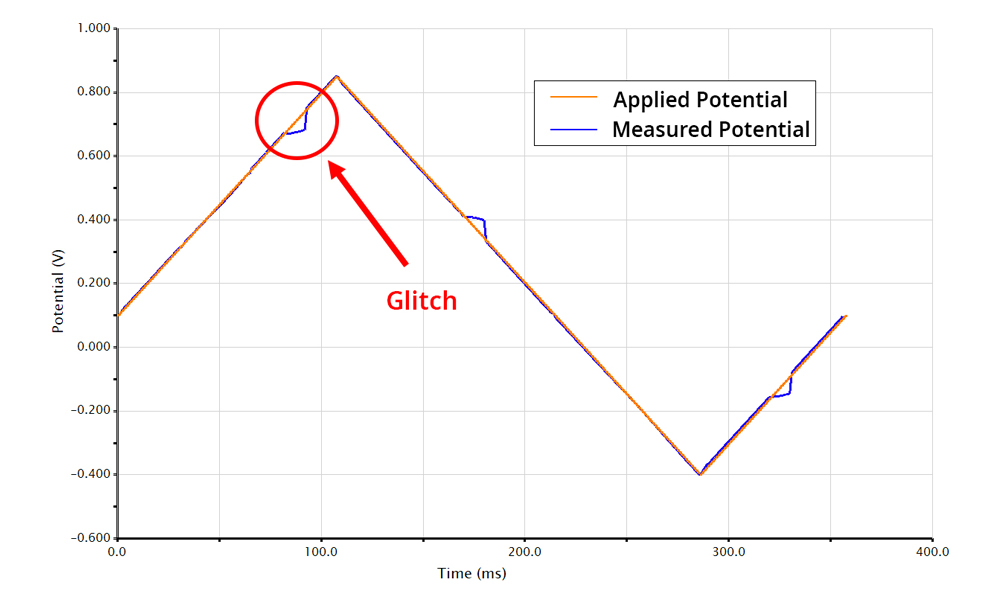
Figure 2. Measured (blue) vs applied (orange) potential waveform which glitches associated with Autorange.
In figure 2, the measured and applied potential should overlap one another, however, there several points where the measured deviates from the applied potential. When you overlay the waveform with the current vs time, (figure 3), you can see several areas where a glitches in both the voltage and current coincide.
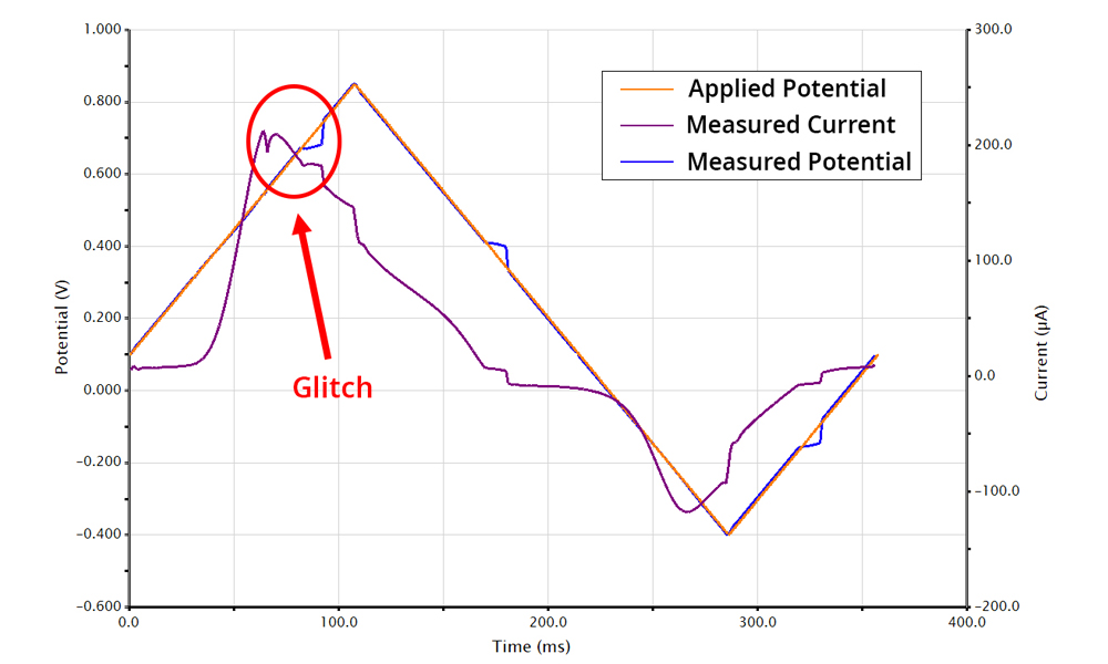
Figure 3. Overlay of current (purple), applied potential (blue), and measured potential (orange) for a cyclic voltammogram with glitches due to Autorange.
2.3Stability Filter
A potentiostat operates on the principle of feedback. The potentiostat is constantly receiving feedback from the cell to maintain a set potential. How fast the potentiostat responds to changes in the electrochemical cell is controlled through the stability filter. If the stability filter is too fast (a high frequency), you will observe fast oscillations when there is a large potential jump. If the stability filter is too slow (a low frequency), it won't respond quickly enough to a change in potential, also resulting in oscillations.
Feedback and the stability filter is like driving a car. As you drive, you are reacting to the driver in front of you to maintain a constant distance. If the driver in front is driving fast, you speed up, but if the driver is driving slowly, you slow down. Feedback is your ability to gauge how fast the driver in front of you is driving, and the stability filter is your reaction time. If your reaction time is too fast (stability filter at a high frequency), then every time the driver in front of you drives a little faster you slam on the gas, but then realize you're getting too close, then you slam on the breaks. You switch between driving too fast and too slow the ride is very bumpy.
Conversely, if your reaction time is too slow, you find yourself speeding up after the car in front is way ahead of you. If you don't break in time, you run the risk of crashing your car. If the stability filter is too low, the potential could drift past the desired value without the potentiostat adjusting.
When the potentiostat switches electrode ranges, there is a temporary disconnect between the electrochemical cell and the potentiostat. As the potentiostat re-establishes a connection with the cell, this is a time where the stability filter has to adjust to the change in potential from the disconnect. If the stability filter is too high you will observe oscillations near the point where the range was switched. Conversely if the stability filter is too low you would also observe slower oscillations that take longer to stabilize.