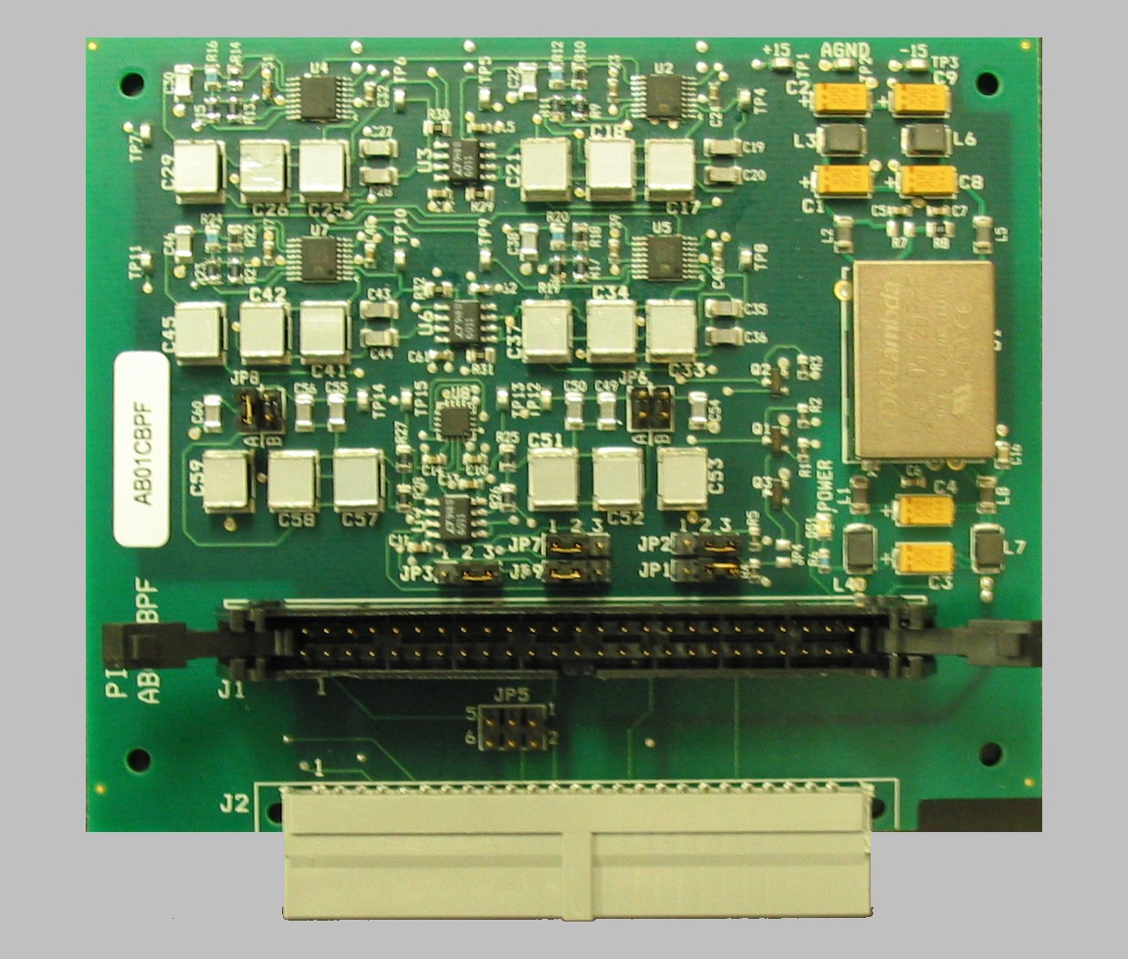
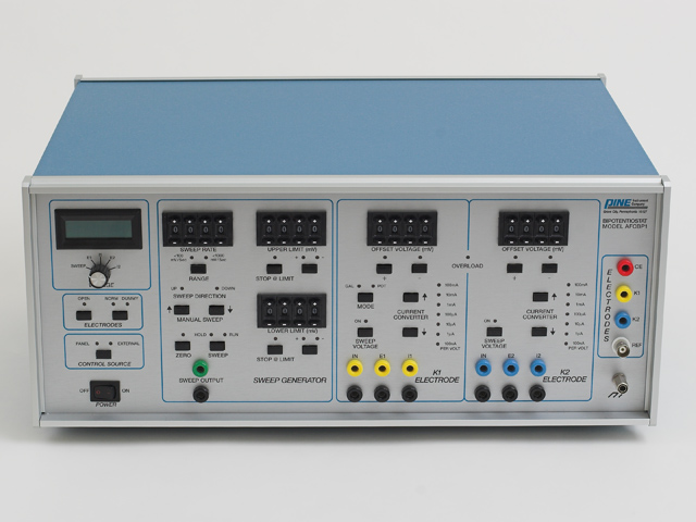
This article describes how to install a signal filter board inside a CBP bipotentiostat system. This board is available as an upgrade option for older CBP systems which do not already have an installed filter board. The part number for this board is AB01CBPF. Contact Pine for further details if you wish to obtain this board for your system.
Jumper Configuration
 The signal filter board provides low-pass filters for both the excitation and response signals which travel between the interface board and the bipotentiostat through the interface cable. There are multiple jumpers on the filter board which are used to select the cutoff frequencies for the various low-pass filters. Prior to installing the filter board in the bipotentiostat, you should check the jumpers to assure that they are set to the desired cutoff frequencies.
More information regarding how to set the jumpers on the filter board can be found at the following link:
A new filter board usually ships with a 1000 Hz cutoff frequency for excitation signals and a 10 Hz cutoff frequency for the response signals.
Board Installation
The installation process is broken up into four major steps below.
- Release the “Swing Locks”
- Disconnect the power cord from the bipotentiostat.
- Remove the top cover from the bipotentiostat and locate the 50-pin connector on the main analog board.
- The 50-pin connector is designated as “J10” and is labeled with the words “TO COMPUTER”.
- Using both hands, carefully release the two “swing locks” by pushing outward and downward on both lock levers at the same time.
As the swing locks are released, the ribbon cable is pushed out of the connector. - Examine the ribbon cable and take special notice of the location of the “key ridge” on the connector.
- Engage Swing Locks on Connector “J1”
- Locate the connector designated as “J1” on the filter board.
- Align the key ridge on the ribbon cable with the matching key slot on connector “J1” on the filter board.
- Push the ribbon cable connector “J1” while applying even pressure to avoid bending any of the pins.
- As the ribbon cable is pushed into the connector, the swing locks on connector “J1” should engage and click into place. It may be necessary to gently push on the lock levers to assist the locking mechanism.
- Finish the Installation
- Push connector “J2” on the filter board into connector “J10” on the main analog board.
- Once again, pay close attention to the swing locks on connector “J10” and assure that they engage and click into place.
- Replace the top cover on the bipotentiostat.
Additional Resources
Related Hardware Links: Signal Filter Settings, CBP Bipotentiostat, Interface Boards
Related Software Links: AfterMath, PineChem, NIDAQ Device Driver


Comments: