This article is part of the AfterMath Data Organizer Electrochemistry Guide
Detailed Description
Like most of the other electrochemical techniques offered by the AfterMath software, this experiment begins with an induction period. During the induction period, a set of initial conditions is applied to the electrochemical cell and the cell is allowed to equilibrate to these conditions. The default initial condition involves holding the working electrode potential at the Baseline Potential for a brief period of time (i.e., 3 seconds).
After the induction period, the potential of the working electrode is stepped through a series of pulses from the Initial potential to the Final potential. The potential is incremented with each successive pulse according to the Pulse increment. Current is measured at the time obtained by subtracting the Sample window from the Pulse width. Cyclic Normal Pulse Voltammetry (CNPV) consists of a cycling (through a series of potential pulses also) the potential of the working electrode between an Upper potential and a Lower potential. Reverse Normal Pulse Voltammetry (RNPV) is a variant of NPV where you choose to apply a Baseline potential in a region where faradaic current is flowing at a maximal rate ( from
).
After the pulse sequence has finished, the experiment concludes with a relaxation period. The default condition during the relaxation period involves holding the working electrode potential at the Final potential for an additional brief period of time (i.e., 1 seconds).
At the end of the relaxation period, the post experiment idle conditions are applied to the cell and the instrument returns to the idle state.
Current is sampled during each pulse and is plotted as a function of the potential applied to the working electrode, resulting in a voltammogram.
Parameter Setup
The parameters for this method are arranged on various tabs on the setup panel. The most commonly used parameters are on the Basic tab, and less commonly used parameters are on the Advanced tab. Additional tabs for Ranges and Post experiment idle conditions are common to all of the electrochemical techniques supported by the AfterMath software.
Basic Tab
For NPV, you can click on the “I Feel Lucky” button (located at the top of the setup) to fill in all the parameters with typical default values (see Figure 1). You may need to change the Baseline potential, Initial potential and Final potential, to values which are appropriate for the electrochemical system being studied.
Figure 1: Basic setup for NPV.
There is no separate Experiment to choose for RNPV, rather you are entering the parameters so as to begin in a region where a faradaic current flows at a maximal rate ( from
) upon application of the Baseline potential. You can click on the “I Feel Lucky” button (located at the top of the setup) to fill in all the parameters with typical default values (see Figure 2). You will likely need to change the Baseline potential, Initial potential and Final potential, to values which are appropriate for the electrochemical system being studied.
Figure 2: Basic setup for RNPV.
For CNPV, you can click on the “I Feel Lucky” button (located at the top of the setup) to fill in all the parameters with typical default values (see Figure 3). You may need to change the Baseline potential, Number of segments, Initial potential, Upper potential, Lower potential, and Final potential, to values which are appropriate for the electrochemical system being studied.
If you choose any odd number of segments greater than two, the parameters that must be entered are a little different than the two segment case. You must choose a Baseline potential, Initial Potential, Upper Potential, Lower Potential, and Final potential. You must also choose whether the Initial direction is rising (pulses toward Upper Potential) or falling (pulses toward Lower Potential). If the Initial direction is rising, the Final potential must be different than the Lower potential. If the Initial direction is falling, the Initial potential must be different than the Lower potential.
If you choose any even number of segments greater than two, the parameters that must be entered are the same as the three segment case. You must choose an Baseline potential, Initial Potential, Upper Potential, Lower Potential, and Final potential. You must also choose whether the Initial direction is rising (pulses toward Upper Potential) or falling (pulses toward Lower Potential). If the Initial direction is rising, the Final potential must be different than the Upper potential. If the Initial direction is falling, the Initial potential must be different than the Lower potential.
Figure 3: Basic setup for CNPV.
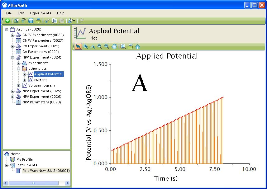
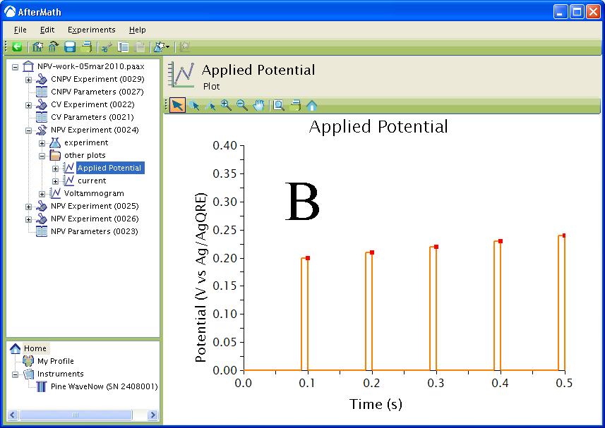
The waveform that is applied to the electrode for all three techniques consists of a series of Pulse periods with a potential step, for a specified time, from a baseline potential near the end of each period (see Figure 4). The potential step is incremented with each period until the final potential is reached. During each potential pulse, the current is measured at a specified time before the end of the pulse. For CNPV, the pulse sequence starts at the Initial potential and is then cycled between the Upper potential and Lower potential for one less than the specified number of segments. The final segment steps from the Upper potential or Lower potential to the Final potential depending if the Initial direction was rising or falling.


Figure 4 : Waveform. Orange trace – applied potential, red squares – current sampled. A: Waveform. B: Zoom of Waveform.
Advanced Tab
The Advanced Tab for this method allows you to change the behavior of the potentiostat during the induction period and relaxation period. By default, the potential applied to the working electrode during the induction and relaxation period will match the initial potential and final potential, respectively, as specified on the Basic Tab. You may override this default behavior, and you may also change the durations of the induction and relaxation periods if you wish.
Ranges Tab
Though AfterMath has the ability to automatically select the appropriate ranges for voltage and current during an experiment it is best to manually select the current range for any pulse technique. Please see the separate discussions on autoranging and the Ranges Tab for more information.
Post Experiment Conditions Tab
After the Relaxation Period, the Post Experiment Conditions are applied to the cell. Typically, the cell is disconnected but you may also specify the conditions applied to the cell. Please see the separate discussion on post experiment conditions for more information.
Typical Results
The typical results for NPV of a solution of Ferrocene in
show a sigmoid-shaped curve (see Figure 5, specific parameters were:
Pt WE, Pt mesh CE, Baseline Potential =
, Initial Potential =
, Final Potential =
, Pulse increment =
, Pulse period =
,Pulse width =
, Sample width =
).
Figure 5: Typical NPV results for Ferrocene in
The typical results for RNPV of the same Ferrocene in
also show a sigmoid-shaped curve (see Figure 6, specific parameters were: Baseline Potential =
, Initial Potential =
, Final Potential =
, Pulse increment =
, Pulse period =
,Pulse width =
, Sample width =
).
Figure 6: Typical RNPV results for a Ferrocene Solution.
Finally, the typical results for CNPV (two segments) of the same Ferrocene in
show two sigmoid-shaped curves (see Figure 7, same conditions as Figure 6). Since Ferrocene is fully-reversible electrochemically, the two sigmoids overlap.
Figure 7: Typical CNPV results for a Ferrocene Solution.
Theory
The following is a brief introduction to the theory of NPV. Please see Bard and Faulkner1 for additional information on the technique. NPV is a derivative technique of Normal Pulse Polarography (NPP). NPP is a technique that was traditionally used with Dropping Mercury Electrodes and Static Mercury Dropping Electrodes. The waveform for the two techniques is the same, however it is appropriate to use the term “Normal Pulse Voltammetry” when referring to the application of the waveform to nonpolarographic electrodes.
Consider a reaction , where
is reduced in a one electron reaction to
with formal potential
>. The application of a baseline potential should be sufficiently positive of
such that no faradaic current flows. After a period of time (
–
),
, the potential of the working electrode is stepped to a more negative value for some time. The total time from the application of the baseline potential through the application of the potential pulse is
.
The potential pulse is incrementally increased with each cycle. As the potential of the working electrode approaches faradaic current flows due to the reduction of
to
. Upon the application of the baseline potential in the next cycle,
is oxidized back to
. When the potential of the working electrode gets sufficiently negative of
,
is reduced to
at a maximum rate and the current plateaus. The magnitude of this current plateau is given by
where is the number of electrons,
is Faraday's Constant (
),
is the electrode area (
),
is the diffusion coefficient(
),
is the concentration (
) and
and
are as described above.
As seen in the Typical Results section, RNPV gives the same wave shape but not the same current. These results are analogous to DPSCA where the current during the forward pulse is different than the current in the reverse pulse. Here in RNPV, the baseline potential is such that is being reduced to
at a maximum rate. As the potential of the working electrode approaches
a faradaic current flows due to the oxidation of
to
. Once the potential of the working electrode is sufficiently positive of
,
is being oxidized at a maximum rate and the current plateaus. The magnitude of this current plateau is give by
where the parameters are as described above. Notice that in the Typical Results section, there is a slight anodic current flowing at the beginning of the experiment. The magnitude of this current is given by the equation
where the parameters are as described above. The magnitude of this current is the difference between the NPV and RNPV currents.
Application
The first example uses NPV to confirm a diffusion coefficient calculated initially by CA. Oyaizu et al.2 produced an organic radical polymer to be used in charge-storage applications. The current in this case is controlled by diffusion of the counter ion through the film.
The second example also uses NPV to measure a diffusion coefficient. Welch et al.3 measured the diffusion coefficients of a free and DNA-bound organo-metallic complex. NPV was superior to CV in this instance due to the low concentration of species in solution.
The next example uses RNPV. RNPV's useless lies in its ability to examine products from chemical reactions that take place after an electrochemical reaction. Osteryoung et al.4 used RNPV to obtain the backwards rate constant and equilibrium constant for the dimerization of N-methyl-2-carbomethoxypyridinium radical, produced after the electrochemical reduction of the N-methyl-2-carbomethoxypyridinium ion.
References
1. Faulkner, L. R.; Bard, A. J. Polarography and Pulse Voltammetry, Electrochemical Methods: Fundamentals and Applications, 2nd ed.; Wiley: New Jersey, 2000; 261-304.
2. Oyaizu, K.; Ando, Y.; Konishi, H.; Nishide, H. J. Am. Chem. Soc. 2008, 130, 14459–14461.
3. Welch, T. W.; Corbett, A. H.; Thorp, H. H. J. Phys. Chem. 1995, 99, 11757–11763.
4. Osteryoung, J.; Talmor, D.; Hermolin, J.; Kirowa-Eisner, E. J. Phys. Chem. 1981, 85, 285–289.
Additional Resources
Links: Electrochemist's Guide, AfterMath User's Guide, AfterMath Main Support Page
Related Techniques: Differential Pulse Voltammetry (DPV), Square Wave Voltammetry (SWV)


Comments: