 This article is adapted from Section 4 of the User Manual for the Pine Modulated Speed Rotator (MSR).
Related Links: MSR User Manual, MSR Rotator Support Page, Pine Research Instrumentation
Table of Contents
Section 4 – Operation
4.1 – The Rotating Shaft
The electrode shaft normally rotates in a clockwise direction as viewed from the top of the rotator. The upper end of a standard shaft has a (
) outer diameter. When properly mounted in the rotator, the upper
(
) of the shaft is inside the motor unit, while the remaining length of the shaft extends down below the motor unit.
The rotator accepts shafts for use with Rotating Disk Electrodes (RDE), Rotating Cylinder Electrodes (RCE) or Rotating Ring-Disk Electrodes (RRDE). Electrical connection is accomplished using one or more silver-carbon brushes to contact metal surfaces on the upper portion of the rotating shaft. Each shaft is specially designed to provide one or two current paths down to the electrode tip. These current paths are electrically isolated from the mounting area near the top of the shaft.
Figure 4.1: Contact Areas at Top of Rotating Electrode Shafts
For an RDE or RCE shaft (see Figure 4.1, left), the entire metal exterior of the shaft below the insulating spacer is in electrical contact with the disk (or cylinder) electrode. For an RRDE shaft (see Figure 4.1, right), there are two insulating spacers. The portion of the shaft between the two insulating spacers provides electrical contact with the disk electrode. The lower portion of the shaft (below the lower insulating spacer) provides electrical contact with the ring electrode.
Figure 4.2: The Brush Chamber (side view)
4.1.1 – Installing a Shaft
Rotating shaft. Entanglement hazard.
Turn off the power to the rotator and disconnect the power cord from the power source before installing or removing the electrode shaft or before installing or removing an electrode tip on the end of the shaft.
AVERTISSEMENT:
Arbre en rotation. Danger d’enchevêtrement.
Éteignez le rotateur et débranchez le cordon d’alimentation de la source d’alimentation avant d’installer ou d’enlever l’arbre de l’électrode ou avant d’installer ou d’enlever un embout d’électrode à l’extrémité de l’arbre.
WARNING:
Do not use or attempt to rotate an electrode shaft that has been dropped, bent or otherwise physically damaged.
Inspect the shaft to be certain that it is not damaged.
AVERTISSEMENT:
N’utilisez pas et ne tentez pas de mettre en rotation un arbre d’électrode qui est tombé, a été tordu ou a été endommagé physiquement d’une autre manière ou d’une autre.
Inspectez l’arbre pour vous assurer qu’il n’a pas été endommagé.
It is often easier to remove or install a shaft by disconnecting the motor control cable and inverting the entire motor unit on the center post. Several of the photos in this section of the manual show the rotator motor in such an inverted position.
Do not lose the white plastic washer on the door latch.
- Invert the orientation of the motor unit so that it is upside-down as shown. Loosen the latch on the clamshell doors. Open the doors to provide access to the brush chamber.
- If there is a shaft already installed, use the hex driver tool (
, provided) to loosen the two screws on the motor coupling. Do not remove these screws entirely; just loosen them by one or two turns of the hex driver. Usually it is necessary to hold the motor coupling in place with one hand while loosening the screws with the other hand.
- Install the shaft by sliding it through the hole in the lower bearing assembly and into the brush chamber.
- The shaft should be pushed as far as possible into the motor coupling so that the contact brushes are properly aligned with the electrical contact areas on the rotating electrode shaft (see Figure 4.3).
- If the shaft is properly installed, the brushes will contact metal surfaces on the shaft.
- If the shaft is improperly installed, the brushes may contact an insulating gap on the shaft, and the connection to the rotating electrode will fail.
- Use the hex driver tool (
) to securely tighten both hex screws on the motor coupling. Gently tug on the shaft to make sure it is securely mounted in the motor coupling.
- Close the clamshell doors and tighten the latch.
- Remount the motor unit on the center post (in the non-inverted position).
- Reconnect the motor control cable from the control unit to the motor unit.
- Reconnect the power cable from the power source to the control unit.
- With the rotation rate knob in the fully counterclockwise position, turn on the control unit.
- Slowly turn the rotation rate knob clockwise until the shaft rotates between
and
.
- While the shaft is slowly rotating (
to
), inspect the rotating shaft to assure that it is rotating properly about the axis of rotation. If the shaft is wobbling, vibrating, or tilting away from the axis of rotation, then turn off the rotator and remove the shaft from the rotator.
- If the shaft is rotating properly along the axis of rotation, then it is ready for use. Some shafts are actually single-piece electrodes where the electrode tip is permanently attached to the shaft. But most shafts are designed to accept a variety of different tips. For these “shaft and tip” designs, the shaft may remain mounted in the rotator, and changing the tip is a simple matter of unscrewing one tip and then threading a new tip on to the shaft.
A new rotator has tape around the motor coupling to protect the hex screws. Remove this tape and loosen the hex screws if needed to allow the shaft to enter the coupling.
Apply a small amount of a silicon-based grease to the top of the shaft before installing the shaft into the motor coupling. This helps to prevent the shaft from sticking in the coupling.
Figure 4.3: Proper (left) and Improper (right) Shaft Insertion Positions
CAUTION:
Before reconnecting the rotator power cable or the motor control cable to the control unit, be sure the control unit power switch is off and the rotation rate knob is turned to the fully counterclockwise position.
ATTENTION:
Avant de reconnecter le câble d’alimentation du rotateur ou le câble de commande du moteur à l’unité de commande, assurez-vous que l’interrupteur de l’unité de commande est en position éteinte et que le bouton de commande de la vitesse de rotation est complètement tourné dans la position inverse des aiguilles d’une montre.
Do not turn on the rotator or rotate the electrode shaft if the shaft is not securely mounted in the motor coupling.
Inspect the shaft to be certain that it is securely mounted.
AVERTISSEMENT:
Ne mettez pas le rotateur en marche ni l’arbre de l’électrode en rotation si l’arbre n’est pas correctement raccordé au moteur.
Inspectez l’arbre pour vous assurer qu’il est bien fixé.
A “Precision Shaft Alignment Kit” is available separately. This kit includes a dial indicator used to measure the “runout” at the end of the shaft (see Section 7.1 for kit part number).
Do not use an electrode shaft which appears to wobble, vibrate, or tilt away from the axis of rotation while rotating. Such a shaft is either improperly installed or physically damaged. Turn off the rotator, disconnect electrical power, and remove the shaft immediately.
AVERTISSEMENT:
N’utilisez pas un arbre d’électrode qui semble osciller, vibrer ou dévier de l’axe de rotation pendant la rotation. Cet arbre est soit installé de manière incorrecte soit endommagé physiquement. Éteignez le rotateur,déconnectez l’alimentation électrique et retirez l’arbre immédiatement.
Figure 4.4: Installing a Tip on to a Shaft
4.1.2 – Changing the Tip on a Shaft
Rotating shaft. Entanglement hazard.
Turn off the power to the rotator and disconnect the power cord from the power source before installing or removing the electrode shaft or before installing or removing an electrode tip on the end of the shaft.
AVERTISSEMENT:
Arbre en rotation. Danger d’enchevêtrement.
Éteignez le rotateur et débranchez le cordon d’alimentation de la source d’alimentation avant d’installer ou d’enlever l’arbre de l’électrode ou avant d’installer ou d’enlever un embout d’électrode à l’extrémité de l’arbre.
WARNING:
Do not use or attempt to rotate an electrode shaft that has been dropped, bent or otherwise physically damaged.
Inspect the shaft to be certain that it is not damaged.
AVERTISSEMENT:
N’utilisez pas et ne tentez pas de mettre en rotation un arbre d’électrode qui est tombé, a été tordu ou a été endommagé physiquement d’une autre manière ou d’une autre.
Inspectez l’arbre pour vous assurer qu’il n’a pas été endommagé.
WARNING:
Do not use an electrode shaft which appears to wobble, vibrate, or tilt away from the axis of rotation while rotating. Such a shaft is either improperly installed or physically damaged. Turn off the rotator, disconnect electrical power, and remove the shaft immediately.
AVERTISSEMENT:
N’utilisez pas un arbre d’électrode qui semble osciller, vibrer ou dévier de l’axe de rotation pendant la rotation. Cet arbre est soit installé de manière incorrecte soit endommagé physiquement. Éteignez le rotateur, déconnectez l’alimentation électrique et retirez l’arbre immédiatement.
WARNING:
Do not use or attempt to rotate an electrode tip that has been dropped or otherwise physically damaged.
Inspect the electrode tip to be certain that it is not damaged.
AVERTISSEMENT:
N’utilisez pas et ne tentez pas de mettre en rotation un embout d’électrode qui est tombée ou a été endommagée physiquement d’une autre manière ou d’une autre.
Inspectez l’embout d’électrode pour vous assurer qu’elle n’a pas été endommagée.
- When removing a tip from a shaft or installing a new tip on a shaft, use one hand to prevent the shaft from rotating while using the other hand to gently turn the tip.
- Remove the old tip from the shaft by gently unscrewing the tip by hand.
No tools are required to remove a tip from a shaft. - Thread the new tip on to the shaft (see Figure 4.4) and gently tighten it by hand. Never use a tool to tighten the tip on to the shaft.
- Reconnect the motor control cable from the control unit to the motor unit.
- Reconnect the power cable from the power source to the control unit.
- With the rotation rate knob in the fully counterclockwise position, turn on the control unit.
- Slowly turn the rotation rate knob clockwise until the shaft is rotating between
and
.
- While the shaft is slowly rotating (
to
), inspect the rotating shaft and tip to assure that both are rotating properly about the axis of rotation. If the shaft or tip is wobbling, vibrating, or tilting away from the axis of rotation, then turn off the rotator and remove the shaft from the rotator.
- If the shaft and tip are rotating properly along the axis of rotation, then the next step is to mount the electrochemical cell that holds the test solution (see Section 4.2).
Do not use tools on the shaft or electrode tip.
Never use a tool to unscrew a tip from a shaft.
If a tip cannot be removed from a shaft by hand, then contact the factory for further instructions.
ATTENTION:
N’utilisez pas d’outils sur l’arbre ou sur l’embout d’électrode.
N’utilisez jamais d’outil pour dévisser un embout d’électrode d’un arbre.
Si un embout d’électrode ne peut être retirée d’un arbre manuellement, communiquez avec l’usine pour obtenir des instructions supplémentaires.
Before reconnecting the rotator power cable or the motor control cable to the control unit, be sure the control unit power switch is off and the rotation rate knob is turned to the fully counterclockwise position.
ATTENTION:
Avant de reconnecter le câble d’alimentation du rotateur ou le câble de commande du moteur à l’unité de commande, assurez-vous que l’interrupteur de l’unité de commande est en position éteinte et que le bouton de commande de la vitesse de rotation est complètement tourné dans la position inverse des aiguilles d’une montre.
Do not turn on the rotator or rotate the electrode shaft if the shaft is not securely mounted in the motor coupling.
Inspect the shaft to be certain that it is securely mounted.
AVERTISSEMENT:
Ne mettez pas le rotateur en marche ni l’arbre de l’électrode en rotation si l’arbre n’est pas correctement raccordé au moteur.
Inspectez l’arbre pour vous assurer qu’il est bien fixé.
Do not use an electrode tip which appears to wobble, vibrate, or tilt away from the axis of rotation while rotating. Such an electrode tip is either improperly installed or physically damaged. Turn off the rotator, disconnect electrical power, and remove the electrode tip immediately.
AVERTISSEMENT:
N’utilisez pas un embout d’électrode qui semble osciller, vibrer ou dévier de l’axe de rotation pendant la rotation. Ce embout d’électrode est soit installée de manière incorrecte soit endommagée physiquement. Éteignez le rotateur, déconnectez l’alimentation électrique et retirez l’embout d’électrode immédiatement.
A “Precision Shaft Alignment Kit” is available separately. This kit includes a dial indicator used to measure the “runout” at the end of the shaft (see Section 7.1 for kit part number).
4.2 – Mounting the Cell
All cells should be clamped to the side post and also supported from below using the cell platform. For a cell with multiple side ports, carefully orient the cell so that any accessories mounted in the side ports have enough clearance. Smaller cells may be clamped using a traditional laboratory clamp secured to the center port (see Figure 4.5, left). Larger cells may be clamped using a large diameter column clamp (see Figure 4.5, right).
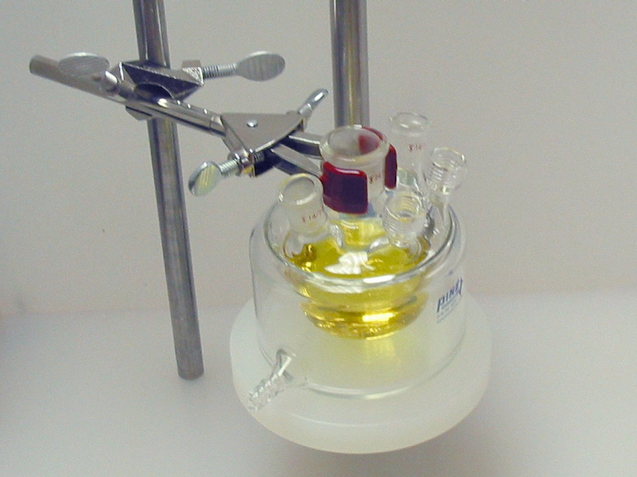
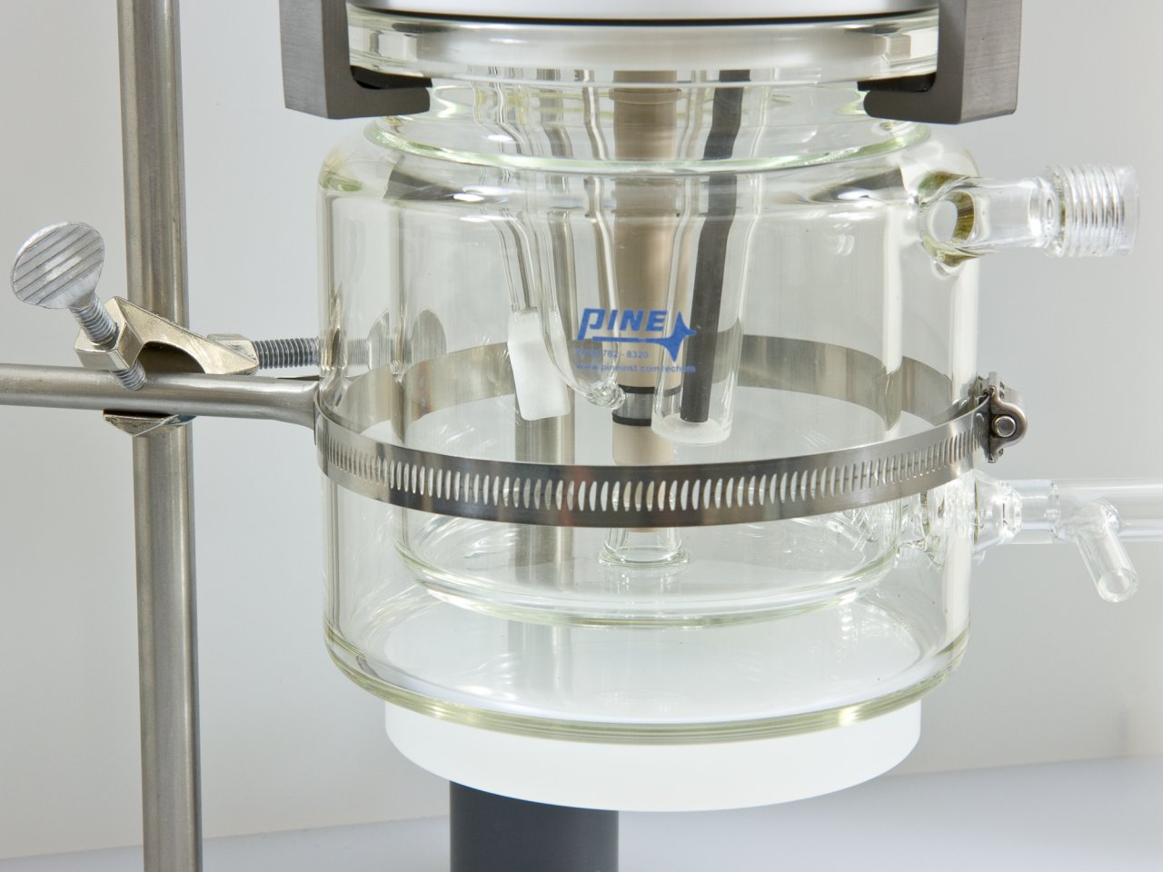
Figure 4.5: Properly Supported and Clamped Electrochemical Cells
The cell platform and clamp positions allow adjustment of the vertical position of the cell with respect to the motor unit. In addition, the vertical position of the motor unit is easily adjusted. Usually, it is easier to mount and clamp the cell in a fixed vertical position. Then, the rotating electrode can be moved vertically down into the cell or up out of the cell as needed.
When raising and lowering the motor unit along the main support rod, be sure to hold the motor unit carefully so that it does not unexpectedly fall and break the glass cell located below the motor unit.
ATTENTION:
Lorsque vous montez ou descendez le bloc moteur le long de la barre principale, veillez à bien le tenir pour éviter qu’il ne chute brutalement et ne casse la cellule de verre située sous le bloc moteur.
Position the motor unit with respect to the glass cell so that the electrode tip is immersed approximately into the test solution.
Excessive immersion may corrode the shaft or tip by allowing liquids to seep into the joint between the shaft and tip.
ATTENTION:
Positionnez le bloc moteur en fonction de la position de la cellule de verre, de telle sorte que l’embout d’électrode soit immergée sur environ 1 cm dans la solution d’essai.
Une immersion excessive peut entraîner la corrosion de l’arbre ou d’embout d’électrode en provoquant l’infiltration de liquides dans le joint situé entre l’arbre et l’embout d’électrode.
Center the rotating electrode within the opening on the cell so that it does not rub against the walls of the opening. Damage will occur if the rotating shaft or tip abrades against these walls.
ATTENTION:
Centrez l’électrode rotative dans l’ouverture de la cellule pour qu’elle ne frotte pas les bords de l’ouverture.
Le frottement des bords de la cellule par l’arbre ou par l’embout d’électrode entraînera des dommages.
4.3 – The Enclosure
Rotating shaft.
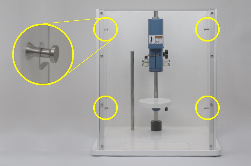
Do not turn on the rotator or rotate the electrode shaft unless the enclosure window is secured to all four pins as shown below.
Use extreme caution when operating the rotator at rotation rates above
AVERTISSEMENT:
Arbre en rotation.
Ne mettez pas le rotateur en marche et ne marche ni l’arbre de l’électrode en rotation si la fenêtre du boîtier n’est pas fermée à l’aide des quatre broches tel qu’indiqué ci-dessous.
Soyez extrêmement prudent lorsque vous utilisez le rotateur à des vitesses de rotation supérieures à .
Figure 4.6: Enclosure Properly Mounted on All Four Pins
After the cell has been mounted and the electrode has been lowered into the cell, securely mount the enclosure by hooking the enclosure to the four pins on the enclosure base (see Figure 4.6).
Note that the enclosure has small openings near the bottom which permit cell connections, purge gas tubing, and coolant to be carefully routed to the electrochemical cell from locations outside the enclosure.
4.4 – Cell Connections
The counter electrode and the reference electrode are usually mounted in appropriate side ports on the electrochemical cell (see Figure 4.7). The counter electrode is often a simple platinum wire or carbon rod to which an alligator clip is easily affixed.
Figure 4.7: Connection of Counter and Reference Electrodes
Always consult the manual for the potentiostat system to determine which cell cable leads should be connected to the counter and reference electrodes. For newer Pine potentiostats, the reference electrode cable is color coded as white, and the counter electrode cable is color coded as green. Many commercially available reference electrodes have a sturdy pin connector on the top end which can accept an alligator clip. The cable which connects the reference electrode to the potentiostat should be of the shielded (coaxial) type, and care should be taken to route this cable well away from noise sources such as power cords, networking cables, or video monitors.
Cell cables on newer model Pine potentiostats use GREEN to mark the counter electrode connection and WHITE to mark the reference electrode connection (see Figure 4.7).
Older Pine bipotentiostats use RED to mark the counter electrode and use a BNC connector for the reference electrode.
There is no universally accepted color coding scheme for marking potentiostat cell cable connections. If you are using the rotator with a third-party potentiostat, consult the potentiostat documentation for information about the cell cable markings.
4.4.1- RDE and RCE Wiring
There are two pairs of brushes which provide electrical contact with the rotating shaft (see Figure 4.8). The upper pair of brush contacts (red) is used to make electrical contact with a rotating disk electrode (RDE) or a rotating cylinder electrode (RCE).
To make good contact on opposite sides of the rotating shaft, both of the red brushes (left and right sides) should be used. Use a short banana jumper cable to connect the opposing brushes together (see Figure 4.8), and then connect the working electrode cable(s) from the potentiostat to the jumper cable.
Figure 4.8: Brush Connections for a Rotating Disk Electrode (RDE) or a Rotating Cylinder Electrode (RCE)
Most modern potentiostats provide separate cable connections for the working electrode “drive” line and for the working electrode “sense” line. The drive line carries current while the sense line measures the potential. Both of these lines must be connected to the rotating electrode brushes. (Note that many older potentiostats use only one cable to carry both the drive and sense signals for the working electrode.)
Cell cables on newer model Pine potentiostats use RED to mark the working electrode “drive” line and ORANGE to mark the working electrode “sense” line. Both of these should be connected to the rotator brushes (see Figure 4.8).
Older Pine bipotentiostats use only one cable connection for both the “drive” and the “sense” signals. This connection is marked with a YELLOW banana jack on the bipotentiostat front panel.
There is no universally accepted color coding scheme for marking potentiostat cell cable connections. If you are using the rotator with a third-party potentiostat, consult the potentiostat documentation for information about the cell cable markings.
4.4.2 – RRDE Wiring
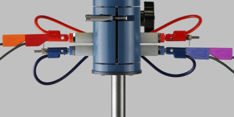
The lower pair of brush contacts are only used with a rotating ring-disk electrode (see Figure 4.9). The lower pair of brushes (blue) contacts the ring electrode while the upper pair (red) contacts the disk electrode. Banana jumper cables are used to short together the opposing brushes in each pair to assure good contact with both sides of the rotating shaft.
It is possible that the brush assemblies on a rotator that has been in use for some time may have been replaced or swapped, and thus, the colors of the brushes may not be as described in the previous paragraph or as shown in Figure 4.9. The important concept to remember is that the UPPER pair of brushes contacts the disk electrode, and the LOWER pair of brushes contacts the ring electrode.
Figure 4.9: Brush Connections for a Rotating Ring-Disk Electrode (RRDE)
A bipotentiostat is required when working with a rotating ring-disk electrode. A bipotentiostat provides independent control of two different working electrodes in the same electrochemical cell.
Cell cables on newer model Pine bipotentiostats use RED and ORANGE to mark the first working electrode drive and sense lines, respectively. Both of these cables must be connected to the upper pair of electrode brushes (red) to contact the disk. Cell cables on newer model Pine bipotentiostats use BLUE and VIOLET to mark the second working electrode drive and sense lines, respectively. Both of these cables must be connected to the lower pair of electrode brushes (blue) to contact the ring.
Older Pine bipotentiostats use only one cable for both the “drive” and the “sense” signals. The YELLOW connection corresponds to the disk, and the BLUE connection corresponds to the ring.
Figure 4.10: Stackable Banana Connector with Optional Stud Connector
The jumper cables used to short the opposing brushes feature stackable banana plugs. If the cell cables from the potentiostat also terminate with banana plugs, then these plugs can simply be inserted directly into either end of the jumper cable. If the cell cables from the potentiostat terminate with alligator clips, then the easiest way to connect such alligator clips is to first insert a banana stud connector into the jumper cable (see Figure 4.10). The small tab on the banana stud provides a good place to attach the alligator clip.
Figure 4.11: Routing Cables out of the Enclosure
4.4.3 – Routing Cables and Tubing
The motor control cable may be routed out of the top of the enclosure to connect the motor unit to the control unit (see Figure 4.11). The enclosure has slots along the bottom of the window that provide clearance for routing cell cables and any tubing out of the enclosure. If required, cables and tubing may be routed through the back panel by drilling small holes in the panel. Any such drilled holes should have a diameter no greater than (
).
4.5 – Proper Grounding
To avoid issues with signal noise when making electrochemical measurements, it is important to properly ground all metal objects near an electrochemical cell to the earth ground. This generally includes the metal chassis of the instrumentation (potentiostat and rotator), the clamps and supports used to physically secure the electrochemical cell, and any peripheral equipment (heaters, stirrers, etc.) used in conjunction with the measurement.
4.5.1 – Terminology
An earth ground connection is available in most modern laboratories via the “third prong” on the power receptacle for the local power system. The power system infrastructure for a laboratory building usually has a long metal probe buried in the earth, and the “third prong” in the building wiring is connected to this earth connection.
A chassis terminal is a connection to the metal chassis surrounding an instrument. Depending upon how the instrument is connected to other experimental apparatus, a chassis terminal may or may not be connected to the earth ground.
In the context of an electrochemical experiment involving a rotating electrode, the DC Common (also known as the signal ground or signal common) is the zero voltage reference point used by the signal measurement (or waveform generation) circuitry in the potentiostat and the rotation control circuitry in the rotator. The DC common may or may not be connected to the earth ground depending upon how the experimental apparatus is arranged and depending upon the internal circuitry of the potentiostat.
4.5.2 – The Earth Ground Connection
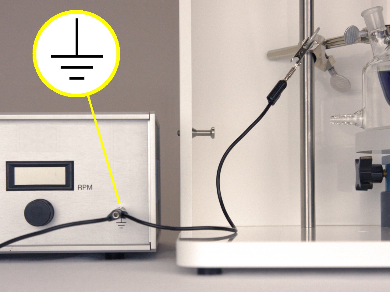
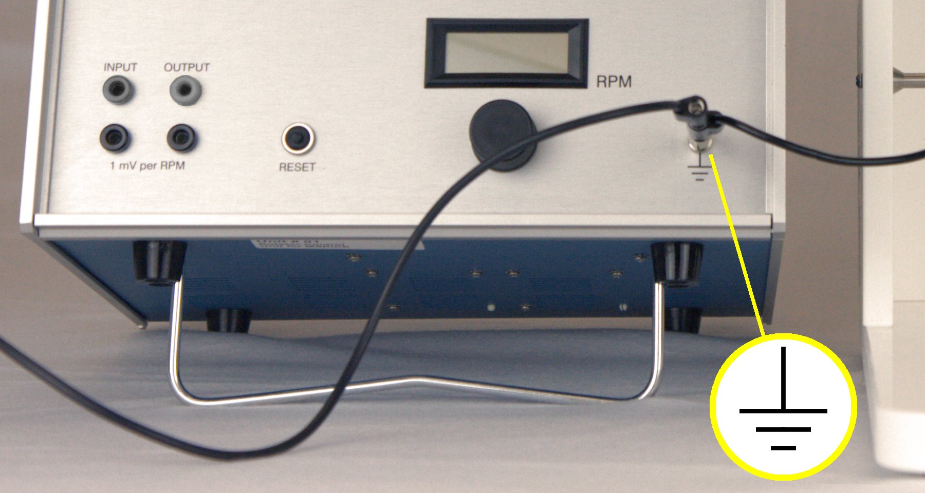
On the front panel of the MSR rotator control unit, there is an earth ground connection (see Figure 4.12). This connection point is in contact with the earth ground via the “third prong” of the power cord. As long as the power system in the laboratory (via the “third prong”) offers a robust connection to the earth, then this front panel connection can be used as an earth grounding point.
It is also very important to note that the chassis of the rotator control unit is in direct contact with the earth ground connector. Thus, it is not possible to isolate the control unit chassis from the “third prong” earth ground.
The chassis of the motor unit is also normally connected to the chassis of the control unit, and thus, to earth ground. This connection is usually made in an indirect fashion. Because the motor control cable (which connects the motor unit to the control unit) is a shielded cable, the shield assures that the chassis of the motor unit and the chassis of the control unit are electrically connected. And because the control unit chassis is connected to earth ground, the motor unit chassis is also in contact with earth ground.
Newer rotators have a shielded motor control cable which has HD-15 connectors on each end of the cable. The shield line in this cable assures that the chassis of the motor unit is in contact with the chassis of the control unit. The chassis of the control unit is, in turn, in contact with earth ground via the “third prong” on the power cord; thus, the motor unit chassis is also earth grounded.
Some older rotator models did not have a shielded motor control cable. These older, unshielded motor control cables are easily recognized because they are permanently connected to the control unit. If working with one of these older rotators, it is necessary to purposefully make a connection from the motor unit chassis to the earth ground connection on the front panel of the rotator control box.
4.5.3 – A Typical Grounding Strategy
While the details of proper grounding for any given electrochemical experiment may differ, a common approach when working with a rotating electrode cell is to connect the chassis of all instruments involved in the experiment to the earth ground at a common point. The earth ground connection on the front panel of the rotator control box serves as a convenient common point for such a strategy. There are two important grounding connections that should be considered in any rotating electrode experiment.
The first important connection is to ground any metal clamps or cell supports near the electrochemical cell (see Figure 4.12). If left ungrounded, these metal objects may act as a source of environmental noise in the measured signals from the electrochemical cell. A simple banana cable with an alligator clip may be used to connect these metal objects to the earth ground.
Figure 4.12: Connect Metal Objects to Earth Ground on Control Box Front Panel
The second important connection that is frequently (but not always) necessary is to connect the potentiostat to the earth ground (see Figure 4.13). If such a connection is to be made, it is important to understand what type of grounding connections are offered by the particular potentiostat being used (consult the potentiostat documentation). Most potentiostats offer either a chassis terminal connection or a signal ground (DC Common) connection. Some potentiostats offer both options, and if this is the case, only one of the two options should be used at a time, preferably the chassis terminal.
Modern potentiostats are usually designed so that electrode connections (working, counter, and reference), the chassis, and the DC Common are all able to “float” with respect to the earth ground. This floating configuration is considered ideal because it gives the researcher maximum flexibility when working with electrochemical cells that may contain an earth grounded component. Compromising the floating configuration (by earth grounding either the chassis or the DC Common) should be avoided when possible, but there are cases where this is the only way to reduce noise in the measured electrochemical signals.
Figure 4.13: Connect Potentiostat to Earth Ground on Control Box Front Panel
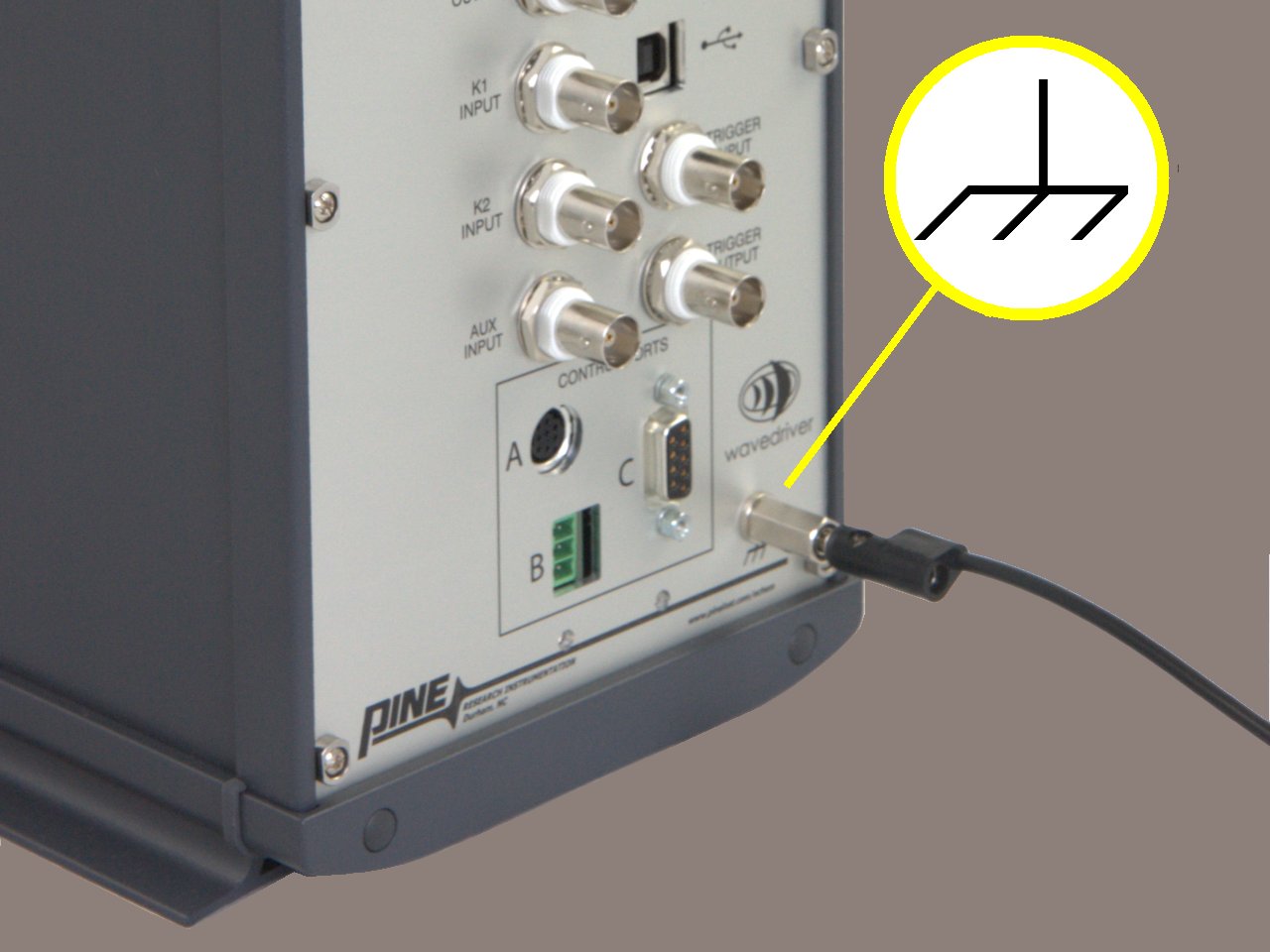
If the potentiostat offers a chassis terminal connection (often located on the back panel of the potentiostat), then connecting this chassis terminal to the earth ground on the rotator control box may (or may not) reduce or eliminate noise in the measured electrochemical signals. For a potentiostat with a chassis that normally “floats” with respect to earth ground, the chassis will no longer be floating after making this direct connection to earth ground.
The chassis terminal on the back panel of the Pine WaveDriver 10 and WaveDriver 20 potentiostats normally “floats” with respect to the earth ground. If the potentiostat chassis is connected to the earth ground on the front panel of the rotator control unit, the potentiostat no longer “floats” with respect to earth ground.
If the potentiostat does not offer a chassis terminal connection (or if earth grounding the chassis terminal is not an option), then a less desirable, but alternative approach is to attempt to make use of the potentiostat’s signal ground (DC Common). If the DC Common (often provided as an alligator clip connection on the cell cable) is connected to the earth ground on the rotator control box, this may (or may not) reduce or eliminate signal noise.
In general, in an electrochemical experiment, it is always ideal to maintain as much isolation between the DC Common, the earth ground, and the instrument chassis as possible. Such isolation increases flexibility when working with electrochemical cells that may contain earth grounded components. But in almost all cases, a cell containing a rotating electrode does not have any earth grounded electrodes, allowing some trade-off between flexibility and the use of earth grounding to reduce signal noise.
4.6 – Using the Rotator in a Glove Box
The rotator may be placed in a glove box when working with air or moisture sensitive compounds. A smaller base (sold separately) is available for use in a glove box (see Figure 4.14).
It is important to understand that the low humidity environment found in most glove boxes increases the rate of wear on both the brush contacts and the internal brushes within the motor itself.
To mitigate the wear rate of the brush contacts, it is recommended that four special low-humidity brushes (sold separately) be installed prior to placing the rotator in the glove box. Contact Pine Research for more details.
Figure 4.14: Glove Box Configuration
Using the rotator in a dry environment such as a low humidity glove box will increase the wear rate of the internal motor brushes.
See Section 6.5 for more information about how to replace a worn motor.
ATTENTION:
L’utilisation du rotateur dans un environnement sec, tel qu’une boîte à gants à faible taux d’humidité augmente la vitesse d’usure des balais internes du moteur.
Consultez la section 6.5 pour en savoir plus sur la manière de remplacer un moteur usé.
4.7 – Rotation Rate Control
Always turn the rotation rate control knob completely counterclockwise (towards the zero rotation rate position) before turning on the rotator.
ATTENTION:
Tournez toujours le bouton de commande de la vitesse de rotation complètement dans le sens inverse des aiguilles d’une montre (vers la position vitesse de rotation égale à zéro) avant de mettre le rotateur en marche.
The fully counterclockwise position corresponds (nominally) to a rotation rate of zero. Even with the knob in this position, there may be some residual rotation (typically less than ) in either the clockwise or counter-clockwise direction.
Always begin each session using the rotator with the power turned off and the rotation rate control knob in the fully counterclockwise position. The fully counterclockwise position corresponds to the slowest rotation rate, and it is always safest to turn on the rotator with the knob in this position.
4.7.1 Manual Control of Rotation
To rotate the electrode under manual control, turn on the control unit power and slowly turn the rotation rate control knob clockwise. As the knob is turned clockwise, the rotation rate increases and the display on the control unit shows the rotation rate.
4.7.2 Monitoring the Rotation Rate
The rotation rate is always displayed on the front panel, but it can also be monitored at the output jacks on the front panel of the control unit. The signal presented at the output jacks is a voltage which is proportional to the rotation rate. The proportionality ratio is .
The rotation rate is controlled to within of the display value selected using the rotation rate control knob. It is normal for the last one or two digits on the display to flicker.
4.7.3 – External Control of the Rotation Rate
It is often convenient for the rotation rate to be controlled via an externally supplied signal. Many potentiostats are capable of providing such a signal to control the rotation rate while simultaneously performing electrochemical measurements. An externally supplied signal is also required when performing hydrodynamically modulated voltammetry, where the rotation rate is varied sinusoidally as electrochemical measurements are made with the potentiostat.
Figure 4.15: Connecting the Rotation Rate Control Cable
A special cable is available to connect Pine potentiostats to the MSR rotator (see Figure 4.15). One line of this cable carries an analog rate control signal from the potentiostat to the INPUT jacks on the front panel of the control box. A second line carrying a digital control signal is connected to the MOTOR STOP jack on the back panel of the control box. The other end of the special cable is connected to the potentiostat.
The analog rate control signal from the potentiostat is a voltage that is proportional to the desired rotation rate. The MSR rotator is factory configured to use a ratio, which is the ratio compatible with Pine potentiostats. Other ratios are available for use with other potentiostats (see Section 6.7).
External control of the rotation rate may involve a signal connection between a potentiostat from one manufacturer being connected to a rotator from another manufacturer. The signals on these various instruments may have been calibrated to different tolerances by each manufacturer. Small signal level differences within these tolerances can add up, causing the actual rotation rate (as displayed on the control unit) to differ slightly from the specified rotation rate (as entered by the user of the potentiostat software).
4.7.4 – External Motor Stop Control
An external digital signal can be applied across the MOTOR STOP banana jacks on the back panel to bring the rotator to a complete stop (see Figure 2.4). This digital signal can be used by a potentiostat or other external instrument to assure that the rotation rate is actually zero. The logic for this digital signal may be either “active HIGH” or “active LOW”.
For the Pine MSR rotator, the MOTOR STOP is configured at the factory to use “active HIGH” logic. If desired, a jumper setting inside the control box can be configured to use the opposite logic (see Section 6.8 for details).
If the MOTOR STOP logic is configured to be “active HIGH”, then the motor is allowed to rotate if a signal greater than is applied across the MOTOR STOP banana jacks. If the two banana jacks are shorted together (i.e., if the MOTOR STOP stop signal is driven to ground), then the motor stops rotating.
If the MOTOR STOP logic is configured to be “active LOW”, then the motor will stop if a signal greater than 2.0 volts is applied across the MOTOR STOP banana jacks. If the two banana jacks are shorted together (i.e., if the MOTOR STOP signal is driven to ground), then the motor is allowed to rotate.
4.8 – Circuit Protection
The power switch on the back panel also acts as a circuit breaker to help protect the control unit circuitry. If the circuit breaker trips, then it can be reset by turning the power switch to the full “off” position and then turning the switch back “on” again.
A secondary circuit breaker on the front panel protects the windings in the motor. If this circuit breaker trips, then the circuit breaker can be reset by pressing the “RESET” button on the front panel.












Comments: