mobile-main-menu-button
Menu

Category Archives: Uncategorized

  • CBP Potentiostat: Interface Board Serial Number

    On occassion, it is necessary to provide the interface board serial number to Pine. The interface board serial number can be obtained using the PineChem software, the Measurement & Automation Explorer (MAX) utility, or the AfterMath Data Organizer software (see below).

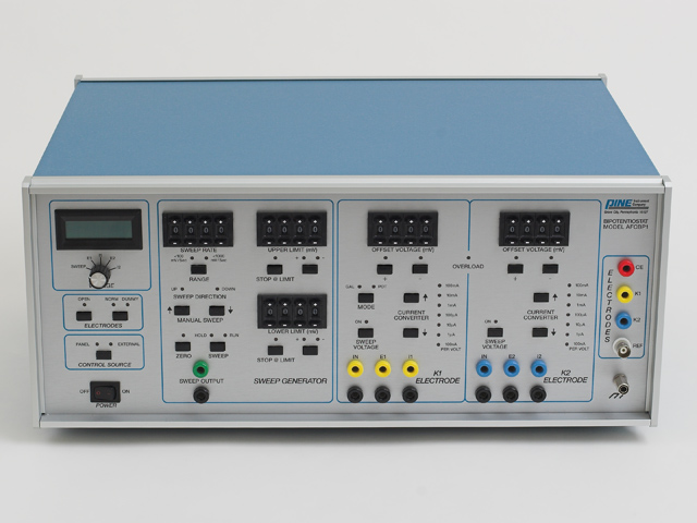
    afcbp1.jpg

    PineChem

    Information about the interface board can be viewed using the “Instrument→Select Device” menu as shown below.

    bipot_serial_pinechem_01.jpg bipot_serial_pinechem_02.jpg

    PineChem CBPTEST Utilty


    The “CBPTEST” application can be found in the Start » Programs » Pine » PineChem menu.

    bipot_serial_cbptest_.jpg

    NIDAQ Device Driver

    Use the “Measurement & Automation Explorer” tool. Note that the interface serial number is given in hex as shown in the screenshot below. (Click here for NIDAQ device driver installation instructions)

    bipot_serial_national_instruments_-_measurement_automation_.jpg

    AfterMath

    The interface board serial number appears in the lower-left pane and will also appear in two other places on the right pane once the instrument is selected in the lower-left pane.

    bipot_serial_aftermath_.jpg

    Additional Resources

    Read More
  • CBP Bipotentiostat: NIDAQ Device Driver

    Control of the CBP Bipotentiostat using either the traditional PineChem software package or the newer AfterMath software package requires installation of the proper version of the NIDAQ device driver on your computer. To select the proper NIDAQ version from the tables below, you need to know which version of the Windows operating system you are using and which interface board model you are using.

    afcbp1.jpg

    AfterMath

    If you are using a PCI-6251, PCI-6259, PCI-6030E, PCI-6040E, PCI-MIO-16XE10, or PCI-MIO-16E-4 interface board with AfterMath, then download the appropriate device driver from the table below.

    Operating System

    Windows 10
    Windows 8 (32 or 64 bit)
    Windows 7 (32 or 64 bit)
    Windows Vista (32 or 64 bit)
    Windows XP (32 bit only)

    Device Driver Version

    NIDAQmx 17.1 (MAY 2017)
    NIDAQmx 14.2 (NOV 2014)
    NIDAQmx 14.2 (NOV 2014)
    NIDAQmx 14.2 (NOV 2014)
    NIDAQmx 8.9.5 (AUG 2009)

    Legacy Note: If you are attempting to use the very old AT-MIO-16E-10 interface board with AfterMath, then you will need a Windows XP system equipped with a legacy ISA slot, you will need to install legacy NIDAQ 7.4.4 (MAR 2007), and you will need to click here for additional instructions.

    PineChem

    If you are using a PCI-6030E, PCI-6040E, PCI-MIO-16XE10, PCI-MIO-16E-4, AT-MIO-16E-10, or AT-MIO-16H-9 interface board with PineChem, then download the appropriate device driver from the table below. You should also click here for additional instructions.

    Operating System

    Windows XP (32 bit only)
    Windows NT
    Windows 2000
    Windows 98
    Windows 95

    Device Driver Version

    legacy NIDAQ 7.4.4 (MAR 2007)
    legacy NIDAQ 7.4.4 (MAR 2007)
    legacy NIDAQ 7.4.4 (MAR 2007)
    legacy NIDAQ 6.9.2 (FEB 2002)
    legacy NIDAQ 6.9.2 (FEB 2002)

    Legacy Note: If you are attempting to use the very old AT-MIO-16E-10 interface board with PineChem, then you will need a computer system equipped with a legacy ISA slot. You will need to install the appropriate version of the legacy NIDAQ device driver as listed above, and you will need to click here for additional instructions.

    Legacy Note: If you are attempting to use the very old AT-MIO-16H-9 interface board with PineChem, then you will need a Windows 95/98 computer system equipped with a legacy ISA slot. You will need to install the appropriate version of the legacy NIDAQ device driver as listed above.

    Installation

    In general, installation of the driver is a simple matter of unzipping the device driver package to a temporary folder on your hard drive and then clicking on the “setup.exe” file.

    IMPORTANT SECURITY NOTE: The NIDAQ driver should always be installed from a Windows user account which has administrative privileges. If the user who will routinely be using the AFCBP1 Bipotentiostat does not have an account with administrative privileges, then special steps must be taken to assure that the user is granted access to certain installation folders. Click here for more details about this issue.

    Activation

    After you have installed the device driver on your computer (and after you have physically installed the interface board inside your computer), you should run the Measurement & Automation Explorer (MAX) utility. The MAX utility is installed on your desktop when you install the NIDAQ device driver.

    Using the MAX utility, look inside the “Legacy NIDAQ Devices” folder and make certain that your interface board appears. The interface board usually appears as a “PCI-MIO-16E-4” board in the list of legacy devices. It is usually assigned a device number equal to one (1).

    Additional Resources

    Related Hardware Links: CBP Bipotentiostat, Interface Boards

    Related Software Links: AfterMath, PineChem, NIDAQ Device Driver

    Read More
  • CBP Bipotentiostat: Filter Board


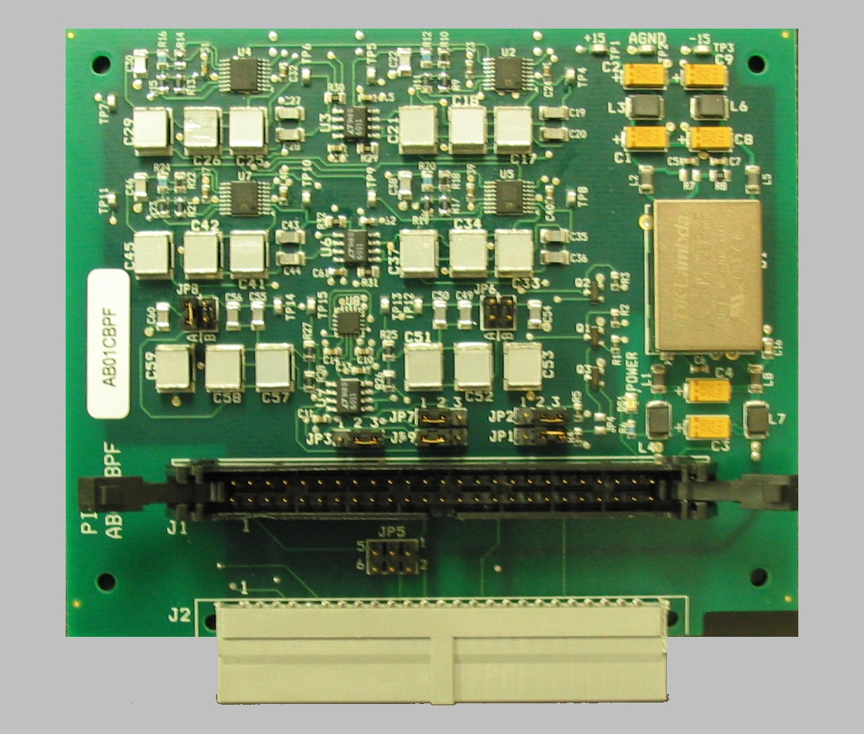
    This article describes how to install a signal filter board inside a CBP bipotentiostat system. This board is available as an upgrade option for older CBP systems which do not already have an installed filter board. The part number for this board is AB01CBPF. Contact Pine for further details if you wish to obtain this board for your system.

    afcbp1.jpg

    Jumper Configuration

    cbp_filter_board.jpgThe signal filter board provides low-pass filters for both the excitation and response signals which travel between the interface board and the bipotentiostat through the interface cable. There are multiple jumpers on the filter board which are used to select the cutoff frequencies for the various low-pass filters. Prior to installing the filter board in the bipotentiostat, you should check the jumpers to assure that they are set to the desired cutoff frequencies.

    More information regarding how to set the jumpers on the filter board can be found at the following link:

    Click Here

    A new filter board usually ships with a 1000 Hz cutoff frequency for excitation signals and a 10 Hz cutoff frequency for the response signals.

    Board Installation

    The installation process is broken up into four major steps below.

    icon_no_power.jpg DISCONNECT POWER:

    Before removing the cover from the bipotentiostat, turn off the power to the bipotentiostat and disconnect the power cord from the power source.

    1. Release the “Swing Locks”
      • Disconnect the power cord from the bipotentiostat.
      • Remove the top cover from the bipotentiostat and locate the 50-pin connector on the main analog board.
      • The 50-pin connector is designated as “J10” and is labeled with the words “TO COMPUTER”.
      • Using both hands, carefully release the two “swing locks” by pushing outward and downward on both lock levers at the same time.
        As the swing locks are released, the ribbon cable is pushed out of the connector.
      ab01cbpf_install_001.jpg
    2. Examine the ribbon cable and take special notice of the location of the “key ridge” on the connector.
    3. ab01cbpf_install_002.jpg
    4. Engage Swing Locks on Connector “J1”
      • Locate the connector designated as “J1” on the filter board.
      • Align the key ridge on the ribbon cable with the matching key slot on connector “J1” on the filter board.
      • Push the ribbon cable connector “J1” while applying even pressure to avoid bending any of the pins.
      • As the ribbon cable is pushed into the connector, the swing locks on connector “J1” should engage and click into place. It may be necessary to gently push on the lock levers to assist the locking mechanism.
      ab01cbpf_install_003.jpg
    5. Finish the Installation
      • Push connector “J2” on the filter board into connector “J10” on the main analog board.
      • Once again, pay close attention to the swing locks on connector “J10” and assure that they engage and click into place.
      • Replace the top cover on the bipotentiostat.
      ab01cbpf_install_004.jpg

    Additional Resources

    Read More
  • CBP Bipotentiostat: Filter Options

    afcbp1.jpg

    Read More
  • CBP Bipotentiostat: NIDAQmx Version 8.9.5

    afcbp1.jpg

    This version of the NIDAQmx device driver is appropriate for use with Windows Vista / XP systems.

    The link below will take you to a web page on the National Instruments web site from which you can download the NIDAQmx driver. Note that National Instruments may require you to create an account on their web site before permitting you to download the device driver.

    Read More
  • CBP Bipotentiostat: NIDAQ MAX Utility

    afcbp1.jpg

    When you install the NIDAQ device driver software on your computer, a special utility program called Measurement and Automation Explorer (or simply “MAX”) is installed. The MAX utility is a software product developed and maintained by National Instruments, Inc. (Austin TX). This utility is often useful for testing and troubleshooting issues with the interface board.

    A brief introduction to the MAX utility can be found on the National Instruments web site at the following link:

    http:/zone.ni.com/devzone/cda/tut/p/id/4638


    Related Hardware Links: CBP Bipotentiostat, Interface Boards

    Related Software Links: AfterMath, PineChem, NIDAQ Device Driver

    Read More
  • CBP Communication Troubleshooting

     A walkthrough guide to solving CBP bipotentiostat communication issues. You may download a PDF version of  this troubleshooting guide.

    This technical notes addresses communication issues that can arise when using the Pine Research Instrumentation AFCBP1 bipotentiostat interfaced to a PC, which controls the bipotentiostat through AfterMathTM Data Organization Software. There are several layers of software and hardware between AfterMath and the CBP bipotentiostat. Each layer must be functioning properly for AfterMath to communicate correctly and efficiently with the potentiostat. When troubleshooting communication issues, a systematic approach must be used to diagnose the problem. Refer to this technical note for the suggested approach.

    Device Driver Software

    The proper device driver software must be installed on the computer. The device driver is from National Instruments and is called “DAQmx”. Older versions of the driver were called “NIDAQ”. These drivers are available as (very large) downloads from National Instruments; however, most customers should have the device driver on a DVD that was shipped to them along with the interface board.

    • Pine Research maintains links to the National Instruments download area (and advice about which versions of the device driver to use).
    • An easy way to tell if DAQmx is present on a computer system is to look for a utility program called “MAX” (which stands for Measurement and Automation Explorer). This is usually on the desktop of any computer which has DAQmx installed. If not, it should be located in the START menu under the “National Instruments” folder.

Proper Board Installation

The physical interface board must be installed in the computer in a full-size PCI slot. Sometimes, after a computer has been moved, the interface board may partially slide out of the slot. Always check to assure that the board is secured in the PCI slot and held in place by a screw.

  • When installing a new board in a new computer, it is generally best to first install the DAQmx driver, then turn off the computer, then install the interface board, and then turn the computer back on. Doing the steps in this sequence helps to assure that Windows properly recognizes the new board after it is installed.

Windows Recognition of Interface Board

Confirm that Windows recognizes and can communicate with the interface board. This is done by using the Device Manager to look at a list of the hardware devices presently installed on the computer. The interface board should appear somewhere in the list. If it doesn’t, then Windows can’t see the board, which means that DAQmx can’t see the board, which means that AfterMath can’t see the board.

  • An example of how the interface board appears in the Device Manager can be seen here
  • If Windows stubbornly refuses to see the board, it is sometimes necessary to remove the board, restart Windows, shut down Windows, reinstall the board in a (preferably different) PCI slot, and restart Windows.
  • Windows can sometimes be tricked into “rediscovering” the board by using the “Scan for Hardware Changes” option in the “Actions” menu of the Device Manager.

DAQmx Communication to Interface Board

Confirm that “DAQmx” can “see” the interface board. This is done by using the MAX utility (Measurement and Automation Explorer). The interface board should appear as one of the attached devices (often under the “Data Neighborhood” or “Legacy Devices” category).

  • There are many different versions of the MAX utility. The link below gives an overview of what actions can be accomplished using the MAX utility (see: http://www.ni.com/white-paper/4638/en).
  • It is possible to use the “Test Panels” feature of the MAX utility to see if the board is “awake” or malfunctioning. Typically, running one of the “Counter” tests is the easiest approach. Just turn on one of the counters (Counter 0 or Counter 1) and a big green indicator on the Test Panel should turn on. This is a pretty good sign that the board is alive and well.

AfterMath Communication with AFCBP1

Confirm that AfterMath can “see” the interface board. When AfterMath starts, it senses the presence of the installed board and a “Pine AFCBP1” entry will appear in the lower-left pane of the AfterMath window. AfterMath will attempt to cold start the instrument and establish some initial “idle” conditions.

  • If AfterMath can see the AFCBP1, but it is not possible to perform any experiments, then a “permissions file” is probably missing from the AfterMath installation. Permissions files can be obtained by contacting Pine. Permissions files are usually located in the AfterMath folder.
  • If AfterMath appears to be in a continuous loop, repeatedly trying to “cold start” the instrument, then the cable is probably loose, or the instrument is not in the proper “External Control” state (see below).

Cable Connections

Verify that the interface cable is secure on both ends. It is very common after moving the instrument or the computer for the cable to come loose from one of the two end connectors.

  • If the cable is secure, but communications problems persist, remove the cable and examine both ends of the cable for bent pins.
  • It is rare (but possible) that the interface port cable located inside the potentiostat may be loose. If this is suspected, disconnect the potentiostat from the power source, remove the cover of the potentiostat, and examine the internal ribbon cables which connect from the back panel down to the main analog circuit board.

AFCBP1 Control Mode

Verify that the potentiostat is turned on and that the Control Mode is set to “external.”

  • The “Control Mode” button is located on the lower-left part of the front panel. It must be pushed and held for about one second to change the control mode to “external”.

Conclusions

If all of the above verification steps have been taken, and the AfterMath is still unable to communicate with the CBP bipotentiostat, then the unit may need to be returned to the factory for repair. Contact Pine Research to arrange a return authorization.

Read More
  • CBP Bipotentiostat: NIDAQ Version 7.4

    Download and Compatibility

    afcbp1.jpg

    This version of the NIDAQ device driver is appropriate for use with Windows XP / 2000 / NT systems.

    The link below will take you to a web page on the National Instruments web site from which you can download the NIDAQ driver. Note that National Instruments may require you to create an account on their web site before permitting you to download the device driver.

    Installation

    ALWAYS INSTALL THE DEVICE DRIVER BEFORE INSTALLING THE INTERFACE BOARD

    SECURITY NOTE: The NIDAQ driver should always be installed from a Windows user account which has administrative privileges. If the user who will routinely be using the AFCBP1 Bipotentiostat does not have an account with administrative privileges, then special steps must be taken to assure that the user is granted access to certain installation folders. See this link for more details.

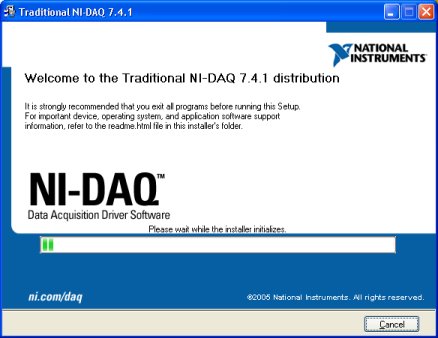
    After launching the NIDAQ installer, it may take several minutes for the installer to initialize itself. During this time, the screen shot shown below will be on the screen:

    ni_install_10.jpg

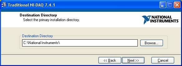
    Once the installer is initialized, it will ask you where you would like to install the NIDAQ software. The default location is in a folder on your system's primary hard drive; however, you may change the location to any folder or any hard drive that you wish.

    ni_install_20.jpg

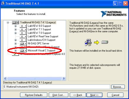
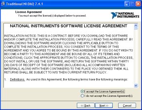
    The next screen will ask you which components of the NIDAQ device driver should be installed on your computer. It is not necessary to install every component. It is important to install the component called “Microsoft Visual C Support” as shown below. You will also be asked to agree with the National Instruments Software License Agreement in order to continue with the installation.

    ni_install_30.jpgni_install_40.jpg

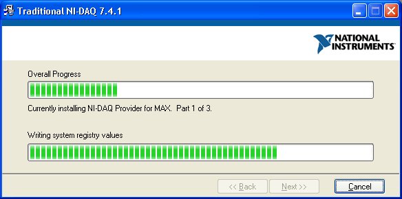
    At this point the installation of NIDAQ on your system will begin. It may take several minutes for all of the required files to be copied to your system's hard drive.

    ni_install_50.jpg

    When the installation process is complete, you will see the following message on the screen. You should click on the “Finish” button.

    ni_install_60.jpg

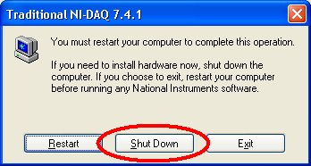
    The last message posted by the installer is shown below. It gives you the option to “restart” or “shutdown” your computer. You should choose the “shutdown” option. This will power down your computer so that it will be ready for you to install the interface board.

    ni_install_70.jpg

    Additional Resources

    Read More
  • CBP Bipotentiostat: NIDAQmx Version 9.2

    afcbp1.jpg

    This version of the NIDAQmx device driver is appropriate for use with Windows 7, Windows Vista, and 32-bit Windows XP systems.

    The link below will take you to a web page on the National Instruments web site from which you can download the NIDAQ driver. Note that National Instruments may require you to create an account on their web site before permitting you to download the device driver.

    Read More
  • CBP Bipotentiostat: NIDAQmx Version 9.5

    afcbp1.jpg

    This version of the NIDAQmx device driver is appropriate for use with Windows 7, Windows Vista, and 32-bit Windows XP systems.

    The link below will take you to a web page on the National Instruments web site from which you can download the NIDAQ driver. Note that National Instruments may require you to create an account on their web site before permitting you to download the device driver.

    Read More