


Legacy Potentiostats
Back to Legacy Potentiostats Back to Legacy Product Support Back to Knowledgebase HomeAFCBP1 Bipotentiostat Diagnostic Guide
Last Updated: 4/30/19 by Neil Spinner
1Abstract
The CBP bipotentiostat system by Pine Research is one of few commercially-available potentiostats that features both software and front panel control. This guide walks a researcher through several diagnostic tests of the CBP bipotentiostat using front panel and software control. These tests aid the researcher to determine if the CBP bipotentiostat is operating correctly, in need of service, or has computer-to-potentiostat communication issues. This guide refers to PineChem and AfterMath templates for the software-controlled diagnostic tests. These templates should have been supplied to you with this document.
2Diagnostic Testing with Front Panel Control
2.1Introduction to the AFCBP1 Front Panel
The CBP bipotentiostat can be operated utilizing the controls on the front panel or through software. Under front panel control, the CBP bipotentiostat can be operated manually without a computer. Note that during front panel (manual) operation, data can only be recorded by connection to a third party X-Y chart recorder or analog data acquisition reader. Throughout this guide, words that appear in ALL CAPITAL LETTERS refer to the front panel element of the same name. For example, VOLTAGE refers to the black knob and LCD panel in the upper left of the front panel of the CBP bipotentiostat (see Figure 1).
2.2Front Panel Setup
Please refer to Figure 1 and Figure 2 to visualize the locations of the front panel controls.
- Disconnect the interface cable between the computer and the potentiostat. The interface cable is located on the center back panel of the potentiostat, labeled “PC Interface Connector"
- On the left side of the front panel, set the CONTROL SOURCE setting to PANEL. You may have to press and hold the CONTROL SOURCE button for longer than 1 sec for the light to switch position
- On the left side of the front panel, set the ELECTRODES setting to DUMMY
- Set the VOLTAGE knob below the LCD display to I1
- Set the parameters in the SWEEP GENERATOR window on the front panel:
- Set SWEEP RATE to 100 mV/s by setting the dial to “100” with the “< 1000 mV/sec” range active
- Set UPPER LIMIT to +1000 mV
- Disable STOP @ LIMIT by pressing the button if the light is “on”
- Press the button under UPPER LIMIT to select the “+” sign
- Set LOWER LIMIT to -1000 mV
- Press button under LOWER LIMIT to select the “-” sign
- In the K2 ELECTRODE window, disable the K2 electrode by pressing the corresponding SWEEP VOLTAGE button until the light goes “off”
- In the K1 WINDOW on the front panel:
- Enable the K1 electrode by pressing the corresponding SWEEP VOLTAGE button until the light comes on
- Set the MODE to “POT” or potentiostat mode
- Set the OFFSET VOLTAGE of K1 to zero (0000 mV)
- Set the CURRENT CONVERTER range to “1 mA/V ”
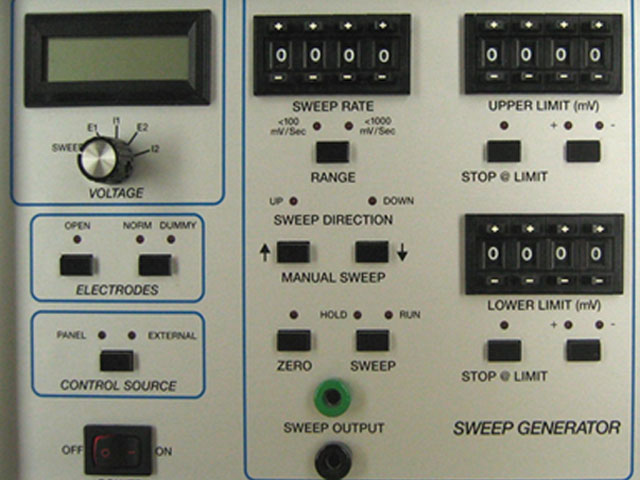
Figure 1. Front Panel (Left Side Only) of the AFCBP1 Bipotentiostat
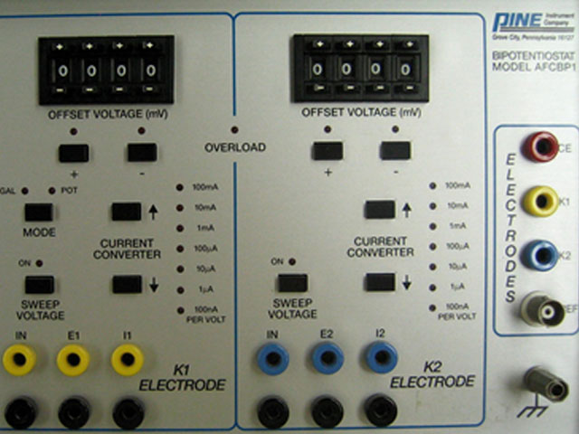
Figure 2. Front Panel (Right Side Only) of the AFCBP1 Bipotentiostat
2.3Front Panel Control Experimental Procedure
- In the SWEEP GENERATOR panel:
- Check that the ZERO light (next to the SWEEP button) is turned “off”
- Start the sweep by setting the SWEEP button to “RUN”
- Watch the front panel LCD meter (upper left hand corner) to make sure that the current slowly sweeps between reading 1.00 (corresponding to +1.00 mA) and reading -1.00 (corresponding to -1.00 mA)
- Switch the VOLTAGE knob to “E1” to monitor the voltage, and it should slowly sweep from 1.00 (corresponding to +1.00 V) to -1.00 (corresponding to -1.00 V)
- Change the CURRENT CONVERTER range from “1 mA/V” to “10 mA/V”. Check the I1 and K1 reading to verify that they are sweeping between 0.10 to -0.10
- Change the CURRENT CONVERTER range from “10 mA/V” to “100 μA/V” and check the I1 and K1 reading to verify that they are now sweeping between 10 and -10
- On the SWEEP GENERATOR panel press the SWEEP button until the light under HOLD is “on”. The LCD meter should stop sweeping and read a constant value
- Press the SWEEP button to turn the light “on” under RUN to start the sweep again
3Diagnostic Test with Internal Dummy Cell and PineChem
Pine Research supports two potentiostat software control packages for the CBP: PineChem
 PineChem Electrochemical Software
and Aftermath.
PineChem Electrochemical Software
and Aftermath.
 AfterMath Downloads
PineChem uses a 12-bit software interface between the CBP and the computer. A CBP with a 16-bit data acquisition interface should be used with Aftermath control software and is not compatible with PineChem.
AfterMath Downloads
PineChem uses a 12-bit software interface between the CBP and the computer. A CBP with a 16-bit data acquisition interface should be used with Aftermath control software and is not compatible with PineChem.
3.1Setup for Software Control of the AFCBP1
- Reconnect the interface cable between the computer and the potentiostat. Ensure that the interface cable between the computer and potentiostat is properly connected at the potentiostat and at the computer
- Press and hold the CONTROL SOURCE button to switch to EXTERNAL control
- Disable the analog SWEEP GENERATOR by pressing the ZERO button
- If present, set the filter knob on the back of the potentiostat to 0 (minimum filtering)
- Check the AC power plugs for the potentiostat, display monitor, and the PC computer. They should all plug into the same power strip and be grounded (3-prong plugs)
- On the computer, start the PineChem software
3.2Running the Test
- Load experimental parameters by pressing the “Load Setup” button and selecting the “CV1.stp” file
- In the parameters field make sure that Experiment Type is set to “Use Internal Dummy Cell”
- Under Signal Sensitivity: K1 Current (Max) is 1 mA
- Press the “Perform” button to execute the test
- Check the CV result and verify that the I1 vs E1 plot is a linear line connecting two points: (-1 mA, -1 V) and (+1 mA, +1 V), see Figure 3
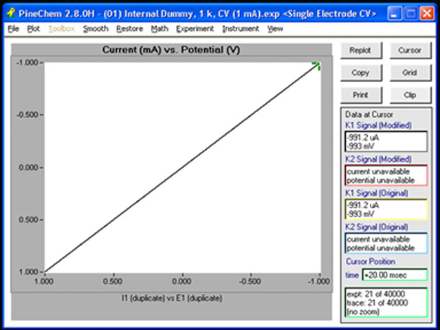
Figure 3. PineChem Screenshot Showing a Cyclic Voltammogram
If the resulting CV is not similar to the result shown in Figure 3, please recheck the experimental settings. Double check the interface cable between the computer and potentiostat. Double check that the Experiment Type is set to ”Use Internal Dummy Cell”. Double check the current range is set to “1 mA”.
4Diagnostic Test with External Dummy Cell and AfterMath
4.1Setup
- Ensure computer and potentiostat are connected
- Switch to front EXTERNAL control by pressing and holding the CONTROL SOURCE button
- Disable the analog SWEEP GENERATOR by pressing the ZERO button
- If present, set the filter knob on the back of the potentiostat to 0 (minimum filtering)
- Check the AC power plugs for the potentiostat, display monitor, and the PC computer: they should all plug into the same power strip and grounded (3-prong plugs)
- Obtain and connect a 1 kΩ resistor
- Connect one end of the resistor to the working electrode lead (K1)
- Short the counter (CE) and the reference (REF) leads together, and connect them to the other end of the resistor (see Figure 4)
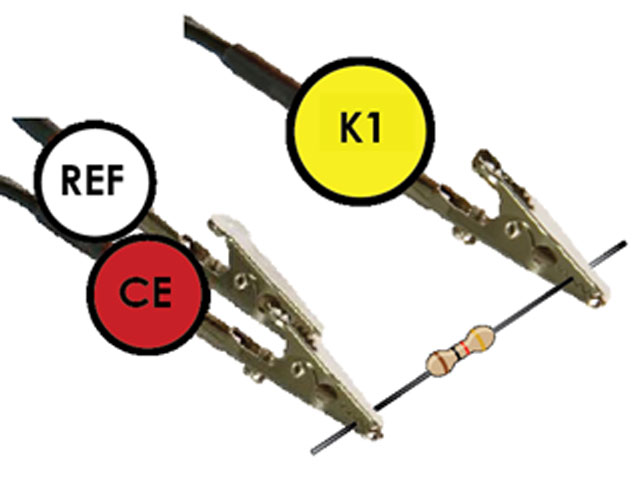
Figure 4. Two-Electrode Configuration for Diagnostic Testing with a Resistor as an External Dummy Cell
4.2Experiment Using AfterMath
- Start AfterMath and from Experiments select Cyclic Voltammetry (CV).
Cyclic Voltammetry (CV)
Select the “I Feel Lucky” button to fill in the values (see Figure 5 for a screen capture of the values for the CV experiment). Perform the CV. For best results, under “Electrode Range” switch Autorange to “Off” and select 1 mA for the “Initial Range”
- Check the CV result and verify that the Current vs Potential plot is a straight line from -1 mA, 1 V to 1 mA, +1 V, similar to that in Figure 3. If not, check the resistor value with a multimeter and check the cell cable
- Change the external resistor to 1 MΩ and repeat the CV experiments. For best results, “Initial Range” can be reduced to the 1 μA range
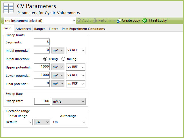
Figure 5. Screen Capture of AfterMath CV setup for Dummy Cell Test Using the "I Feel Lucky" Button
5Diagnostic Testing with Potassium Ferricyanide
5.1Setup for an Electrochemical Experiment
The following describes the setup for an electrochemical experiment:
- Check the connection between the computer and the potentiostat
- Switch to EXTERNAL control by pressing and holding the CONTROL SOURCE button
- Disable the analog SWEEP GENERATOR by pressing the ZERO button
- If present, set the filter knob on the back of the potentiostat to 0 (minimum filtering)
- Check the AC power plugs for the potentiostat, display monitor, and the PC computer: they should all plug into the same power strip with grounded plugs (3-prong plugs)
- Make a 200 mL aqueous solution containing 1 mM K3Fe(CN)6 in 100 mM KCl, and pour ~150 mL into an electrochemical cell, such as AKCELL2 or AKCELL3 from Pine Research
- Equip the cell with a GC working electrode (5 mm OD, mirror-polished), a reference (RREF0021), and a Pt wire counter electrode (AFCTR5)
- Connections between the electrochemical cell and CBP are shown in Figure 6 with 1) Counter electrode (CE); 2) Working electrode (K1); 3) Reference electrode (REF); and 4) Chassis ground
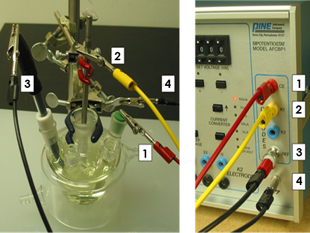
Figure 6. Electrode Setup for Cyclic Voltammetry Diagnostic Testing of the AFCBP1
5.2Experiment - PineChem
- Similarly to the resistor test from above, run a set of CV experiments with several Current Ranges
- Verify that the resulting CVs are similar to those shown in Figure 7
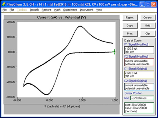
Figure 7. Cyclic Voltammogram (CV) obtained in PineChem of a Potassium Ferricyanide Solution
5.3Experiment - AfterMath
- Similarly to the resistor test from above, run a set of CV experiments with several Current Ranges
- The results should be comparable to those shown in Figure 8
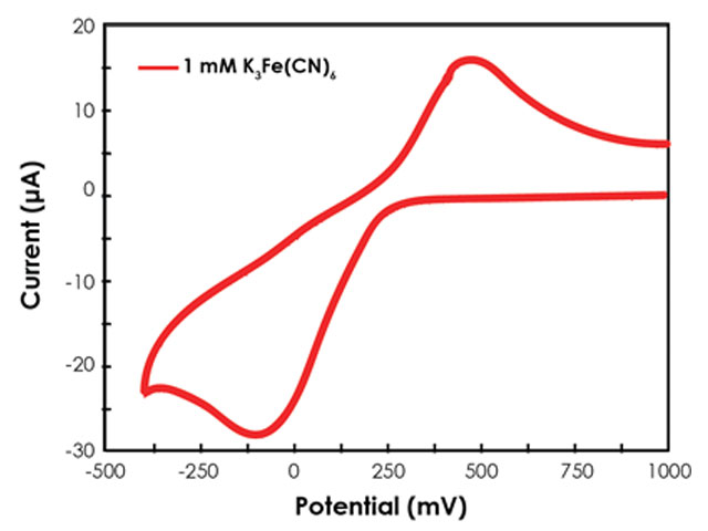
Figure 8. Cyclic Voltammogram (CV) obtained in AfterMath of a Potassium Ferricyanide Solution