


Dual Electrode Electrolysis (DEBE)
Last Updated: 10/12/21 by Alex Peroff
1Technique Overview
Many techniques used in electroanalytical chemistry affect change within a chemical system with small surface area to volume ratios. For example, it is common to conduct stationary cyclic voltammetry (CV) at a 3 mm OD working electrode in 100 mL of solution containing 1 mM electroactive species. In such a system, CV can be performed for long periods of time without appreciably changing the bulk concentration of analyte (oxidized and or reduced species), assuming a nominal 1 mA/cm2 current density. In this case, <1 C passes and the bulk concentration of electroactive species does not appreciably change (~250 mC).
Many techniques used in electroanalytical chemistry affect change within a chemical system with small surface area to volume ratios. For example, it is common to conduct stationary cyclic voltammetry (CV) at a 3 mm OD working electrode in 100 mL of solution containing 1 mM electroactive species. In such a system, CV can be performed for long periods of time without appreciably changing the bulk concentration of analyte (oxidized and or reduced species), assuming a nominal 1 mA/cm2 current density. In this case, <1 C passes and the bulk concentration of electroactive species does not appreciably change (~250 mC).
In contrast to this typical setup, Dual Electrode Electrolysis (DEBE) is conducted with large surface area to volume ratios and often convective stirring for enhanced mass transport. The anticipated outcome is to significantly change bulk solution properties during the course of the electrolysis. Unlike typical CV experiments, DEBE working and counter electrodes are 2 - 4 orders of magnitude larger in area; thus, for a larger working electrode with A = 100 cm2 and the same 1 mA/cm2 current density, >350 C passes through the cell. In this case, all electroactive species in the cell are converted to their reduced form in a short period of time. Often, this is the goal to exhaustively convert analyte from reduced to oxidized form, and vice-versa.
DEBE is often performed in a separated cell, consisting of either two or three chambers, each separated by a porous material like sintered glass disks (frits) or polymer exchange membranes (e.g., Nafion®). The working (WK1 and WK2 are typically separated) and reference electrodes are often placed into one chamber of a separated cell and the counter electrode in another. The working electrode chambers should be stirred to provide maximum mass transport to the electrode during electrolysis. Some electrolysis cells separate each electrode into their own separate chamber. Both the working and counter electrodes should have a large surface area (typically platinum meshes or high surface area carbon meshes, foam, felts and vitreous carbon materials) to increase current (charge) and reduce time to reach exhaustive electrolysis.
Bulk electrolysis can be operated with four different electrode modes:
- controlled potential (POT), where a constant potential is applied and current vs. time is measured
- controlled current (GAL), where a constant current is applied and potential vs. time is measured
- zero resistance ammeter (ZRA), where potential is actively driven to 0 V and current vs. time is measured
- open circuit potential (OCP), where the counter electrode is bypassed such that no current passes and voltage vs. time is measured
Controlled potential bulk electrolysis is by far the most commonly used mode; however, some might use controlled current for select applications. While a potentiostat, with reference feedback, is required for controlled potential bulk electrolysis, simpler instrumentation consisting of only a high voltage power supply (or batteries) and a large resistor can be used. The focus of this article will primarily focus on DEBE in POT mode (constant potential bulk electrolysis) for both working electrode 1 (WK1) and working electrode 2 (WK2).
2Fundamental Equations
Numerous texts thoroughly explain electrochemical theory and should be consulted for a complete understanding of this method.
 Zoski, C. G.; Leddy, J.; Bard, A. J.; Electrochemical Methods: Fundamentals and Applications (Student Solutions Manual), 2nd ed. John Wiley: New York, 2002.
Kissinger, P.; Heineman, W. R. Laboratory Techniques in Electroanalytical Chemistry, 2nd ed. Marcel Dekker, Inc: New York, 1996.
Wang, J. Analytical Electrochemistry, 3rd ed. John Wiley & Sons, Inc.: Hoboken, NJ, 2006.
Kissinger, P.; Heineman, W. R. Laboratory Techniques in Electroanalytical Chemistry, 2nd ed. Marcel Dekker, Inc: New York, 1996.
Wang, J. Analytical Electrochemistry, 3rd ed. John Wiley & Sons, Inc.: Hoboken, NJ, 2006.
Consider the general reaction

where  is reduced to
  in a one electron reaction. A solution of
  moles of would require moles of electrons to completely reduce to . Upon applying a sufficient reducing potential, a large amount of is converted to and subsequently swept away from the rotating electrode. As more is converted to the current falls off exponentially until it reaches background level. It is at this point, the electrolysis can be stopped. The charge
  passed during the experiment can be obtained by integrating the current with respect to time.
is reduced to in a one electron reaction. A solution of moles of would require moles of electrons to completely reduce to . Upon applying a sufficient reducing potential, a large amount of is converted to and subsequently swept away from the rotating electrode. As more is converted to the current falls off exponentially until it reaches background level. It is at this point, the electrolysis can be stopped. The charge passed during the experiment can be obtained by integrating the current with respect to time.
By the following equation, charge can be converted to the number of moles of electrolyzed during the experiment
electrolyzed during the experiment
where  is Faraday's constant (96,485 C/mol) and
  is the number of electrons transferred during the reaction. This analysis is conducted for each chronoamperogram (i.e., separately for WK1 and WK2).
is Faraday's constant (96,485 C/mol) and is the number of electrons transferred during the reaction. This analysis is conducted for each chronoamperogram (i.e., separately for WK1 and WK2).Additional and more complete background of this theory is provided in the Theory section of the Knowledgebase.
 Theory
3Experimental Setup in AfterMath
To perform a dual-electrode electrolysis experiment in AfterMath, choose Dual Electrode Electrolysis (DEBE) from the Experiments menu (see Figure 1).
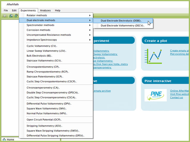
Figure 1. Dual Electrode Bulk Electrolysis (DEBE) Experiment Menu Selection in AfterMath
Doing so creates an entry within the archive, called DEBE Parameters. In the right pane of the AfterMath application, several tabs will be shown (see Figure 2).
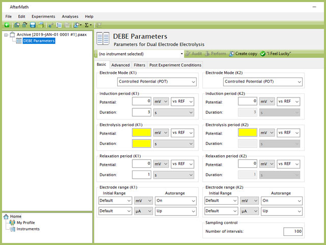
Figure 2. Dual Electrode Electrolysis (DEBE) Experiment Basic Tab
Continue reading for detailed information about the fields on each unique tab.
3.1Basic Tab
The basic tab contains fields for the fundamental parameters necessary to perform a BE-RDE experiment. AfterMath shades fields with yellow when a required entry is blank and shades fields pink when the entry is invalid (see Figure 3).
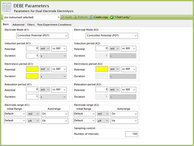
Figure 3. Dual Electrode Electrolysis (DEBE) Parameters Basic Tab
The first selection with DEBE is the Electrode mode (see Figure 3). Controlled potential DEBE for both WK1 and WK2 electrodes is the most commonly used mode. The modes available are summarized as follows:
- Controlled Potential (POT), where a constant potential is applied and current vs. time is measured
- Controlled Current (GAL), where a constant current is applied and potential vs. time is measured
- Zero Resistance Ammeter (ZRA), where potential is actively driven to 0 V and current vs. time is measured
- Open Circuit Potential (OCP), where the counter electrode is bypassed such that no current passes and voltage vs. time is measured
As with most Aftermath methods, the experiment sequence is
Induction Period → Electrolysis Period → Relaxation Period → Post-Experiment Idle Conditions
This sequence is applied to both WK1 and WK2 simultaneously. Unlike most experiments, the Induction and Relaxation Periods are on the Basic Tab. The parameters for a DEBE experiment are fairly simple compared to other methods in AfterMath. A plot of the typical experiment sequence, containing labels of the fields on the Basic tab, helps to illustrate the sequence of events in a DEBE experiment (see Figure 4). Again, given that different electrode modes are possible, the illustrations provided here assume Controlled Potential (POT) mode; however, other modes such as Controlled Current (GAL) are analogous to these figures, with different units on the y-axis.
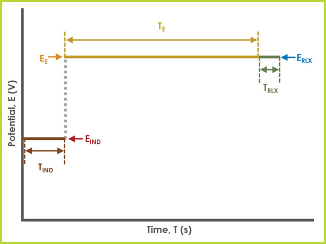
Figure 4. Dual Electrode Electrolysis (BE) Basic Tab Field Diagram
| Group Name | Field Name | Symbol |
| Induction Period | Potential |  |
| Induction Period | Duration |  |
| Electrolysis Period | Potential |  |
| Electrolysis Period | Duration |  |
| Relaxation Period | Potential |  |
| Relaxation Period | Duration |  |
| Sampling Control | Number of Intervals |  |
Table 1. Basic Tab Group Names, Field Names, and Symbols.
During the induction period,
 Induction Period
a set of initial conditions are applied to the electrochemical cell and the cell equilibrates at these conditions at each working electrode. Data are not collected during the induction period, nor are they shown on the plot during this period.
Induction Period
a set of initial conditions are applied to the electrochemical cell and the cell equilibrates at these conditions at each working electrode. Data are not collected during the induction period, nor are they shown on the plot during this period.
After the induction period, the potential applied to each working electrode is stepped to the specified value for the duration of the experiment, which is called the electrolysis period. The potentiostatic circuit of the instrument maintains constant applied potential relative to the reference electrode while simultaneously measuring the current at the working electrodes. During the electrolysis period, potential and current at the working electrodes are recorded at regular intervals as specified on the Basic tab. Sampling control defines the number of intervals (number of data points) collected during the electrolysis period. With Electrolysis period duration, a sampling rate can be defined as,
Users should enter a number of intervals that their analysis requires. Commonly, BE experiments are sampled at a lower rate (1 sample/s). Not all sampling rates are allowed due to differences in hardware (WaveNow series vs. WaveDriver series, for example).
The experiment concludes with a relaxation period.
Relaxation Period
During the relaxation period, a set of final conditions (specified on the Advanced tab) are applied to the electrochemical cell and the cell equilibrates at these conditions. Data are not collected during the induction period, nor are they shown on the plot during this period.
At the end of the relaxation period, the post-experiment idle conditions
Private: Understanding Post Experiment Conditions Tab
are applied to the cell, for each working electrode WK1 and WK2, and the instrument returns to the idle state. The default plot generated from the data is measured potential vs. time, called a chronoamperogram. The chronoamperogram will contain two traces, one for each working electrode (as indicated by the plot legend).
The Electrode Range on the Basic tab is used to specify the expected range of current and/or potential. If the choice of electrode range is too small on a potentiostatic experiment, measured current could be off-scale, appearing as a truncated flat line where the signal exceeded the selected measurement range. Alternatively, if the electrode range is too large for the incoming signal, measured current may have a noisy, choppy, or quantized appearance due to lower than desirable resolution based on range choice. More details on avoiding "the ugly ducking" within the knowledgebase.
Electrode Range
3.2Advanced Tab
The BE Advanced tab contains two groups for iR Compensation and for Experiment End Trigger for both WK1 and WK2 (see Figure 5).
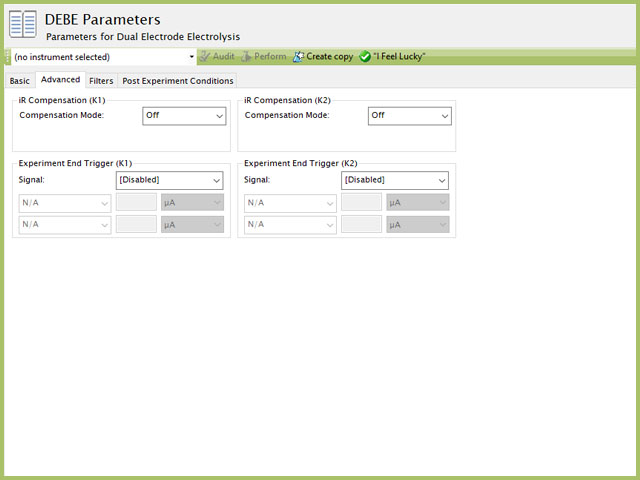
Figure 5. Dual Electrode Electrolysis (DEBE) Parameters Advanced Tab
Detailed description of the iR Compensation Mode is provided elsewhere on the knowledgebase.
What is iR drop?
This mode is used to correct for uncompensated resistance in the electrochemical cell.
In a DEBE experiment, the researcher may want to have AfterMath monitor the response and then stop the experiment a specific current, potential, and/or charge. This value is called a trigger and is set in the Experiment End Trigger group on the Advanced tab (see Figure 5). There are independent triggers available for either WK1 and/or WK2. For DEBE, the signals for the trigger can be potential, current, or charge based on the Electrode Mode selected on the Basic tab (see Figure 3). A common example of using this trigger is in the charging of a battery. A researcher would charge the battery by performing a DEBE Controlled Currrent (GAL) mode selected (also called a CC or constant current) with the trigger set to its upper potential limit (e.g., 100% SOC). Once this potential limit is reached, the DEBE experiment terminates and retains the data collected up to the trigger endpoint.
Another application is in the plating process. If a user wishes to control the deposition layer thickness on a working electrode, they might use a constant potential to drive the reduction at the electrode. In this case, a user may have calculated a theoretical mass they intend to plate to an electrode. Through Faraday's Law (see Section 2), the user can calculate the total charge that must pass to yield the desired mass on the electrode surface. In this case, a user may set an Experiment End Trigger to stop DEBE (at the specfied electrode(s)) after passing this amount of charge. Details on the End Trigger settings are found elsewhere in the knowledgebase.
End Triggers
3.3Ranges, Filters, and Post Experiment Conditions Tab
The Filters tab provides access to potentiostat hardware filters, including stability, excitation, current response, and potential response filters. Pine Research recommends that users contact us
Contact
for help in making changes to hardware filters. Advanced users may have an easier time changing the automatic settings on this tab. Filter settings fields are shown for WK1 (working electrode #1) as well as for WK2 (working electrode #2) regardless of the potentiostat connected to AfterMath. More information on filters is available elsewhere on the knowledgebase.
Private: Understanding the Filters Tab
By default, the potentiostat disconnects from the electrochemical cell at the end of an experiment. There are other options available for what these post-experiment conditions can be and are controlled by setting options on the Post Experiment Conditions tab. Complete details on the fields and settings on this Post Experiment Conditions tab are provided elsewhere on the knowledgebase.
Private: Understanding Post Experiment Conditions Tab
4References
- Zoski, C. G.; Leddy, J.; Bard, A. J.; Electrochemical Methods: Fundamentals and Applications (Student Solutions Manual), 2nd ed. John Wiley: New York, 2002.
- Kissinger, P.; Heineman, W. R. Laboratory Techniques in Electroanalytical Chemistry, 2nd ed. Marcel Dekker, Inc: New York, 1996.
- Wang, J. Analytical Electrochemistry, 3rd ed. John Wiley & Sons, Inc.: Hoboken, NJ, 2006.