


Troubleshooting LPR Experiments
Last Updated: 12/4/23 by Neil Spinner
1Overview
Linear Polarization Resistance (LPR) experiments are extremely complex and involve the use of multiple pieces of equipment, typically including an electrode rotator, potentiostat, electrodes, electrolyte, cells, and other accessories. These myriad devices can contribute to noise and error in LPR data. In addition, the slow, methodical nature of data acquisition during an LPR experiment can also lend itself to noise and error (see Figure 1 for examples of poor and/or noisy LPR data), and oftentimes adjusting certain hardware configurations and software parameters can help alleviate some of these inaccuracies. In this article, some of the methods for troubleshooting LPR experiment noise and error will be discussed.
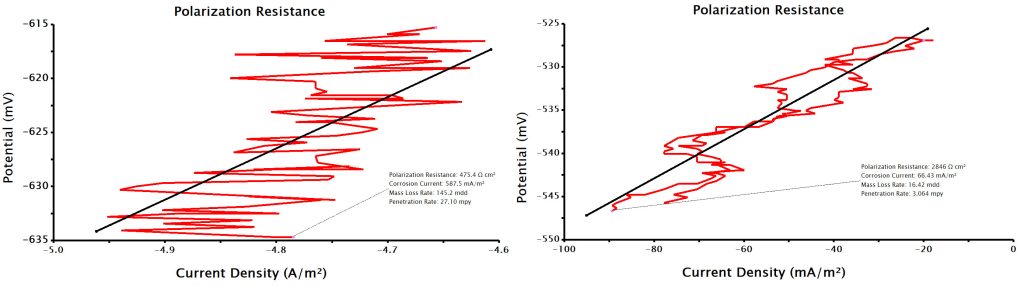
Figure 1. Bad and noisy LPR data.
2Troubleshooting Noise with Hardware
2.1Electrode Rotator
A separate Knowledgebase article has been written detailing the steps that can be taken to troubleshoot noise with an electrode rotator, which can be accessed here: "Troubleshooting Noise in an Electrochemical System with a Rotator"
 Troubleshooting Noise in an Electrochemical System with a Rotator
2.2Electrodes, Cells, and Accessories
Very often, the complexity of the LPR experimental setup lends itself to noise, interruptions, and other problems with the acquired data. The variety of electrodes, cells, and accessories involved creates a multidimensional problem that can be tricky to solve. Below is a list of these items involved in a typical LPR experiment, along with considerations and troubleshooting tips.
- Electrodes
An LPR experiment, much like many electrochemistry tests, normally consists of three electrodes: working, counter, and reference. The working electrode is often a metal cylinder (also sometimes called a coupon) that can either be left stationary or rotated. The counter electrode is often a rod of graphite or steel, and the reference electrode can either be a standard reference couple (such as Ag/AgCl) or a pseudo-reference (such as a rod of hastelloy or stainless steel). In some cases, the same steel rod is used as both the reference and counter electrode, thereby creating a two-electrode setup rather than a three-electrode setup. However, in LPR experiments, a stable reference electrode is important even when the reference is a pseudo-type, at least during the entirety of the LPR scan. Thus, it is not advisable to combine the reference and counter electrodes in a two-electrode setup because passing even a very small current will change the reference potential, thus reducing stability when using a pseudo-reference.
-
- Working Cylinder/Coupon
The working electrode in an LPR experiment is typically a cylinder insert, often referred to as a "coupon," made from a variety of different types of steel (see Figure 2 below). Perhaps the most common alloy of steel used in LPR tests is 1018 carbon steel, which is used in many commercial vessels and pipelines. For this reason, the study of its corrosion, as well as methods to prevent its degradation over time (e.g., by using corrosion inhibitors), is an extremely industrially-relevant process.
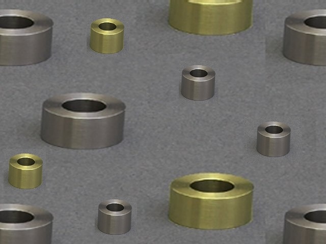
Figure 2. Cylinder inserts (coupons).
Cylinder inserts are normally coated with a protective hydrocarbon layer in the factory to prevent inadvertent and premature corrosion while in storage, or through exposure to elements during transit. This layer can cause severe problems electrochemically if not removed before the LPR experiment, which is often performed in aqueous brine solution, because it interferes with the surface and the electrode-electrolyte interface, usually resulting in erratic or noisy results. Cylinders should be rinsed with a solvent like acetone to dissolve and remove the hydrocarbon film, then thoroughly dried, prior to use in LPR tests.
Another critical error LPR researchers sometimes make is to reuse cylinder inserts for multiple LPR experiments. This is not an advisable practice. Cylinder inserts should be viewed as one-time use electrodes. The reason for this is that an LPR experiment necessarily involves intentional corrosion of the working electrode coupon, and efforts to restore the coupon to its original state for future use are either not possible, or at least unwise even if they are possible. The initial state of the cylinder insert includes a smooth, polished surface and a well-defined surface area (often 3 cm2). After an LPR test, some or all of the surface will be corroded and no longer demonstrate a smooth, polished finish. This means the new surface area will be, at the very least, difficult to know for certain, and considering knowledge of the surface area is critical for the analyses performed on LPR data, a used cylinder should never be used for subsequent testing. In addition, even in the case that a researcher wishes to attempt to repolish a cylinder to a fresh, smooth surface, it is impossible to know the precise extent of corrosion induced during the first LPR experiment such that the new surface area could be easily known, or whether pitting/nucleation points/corroded areas will still be present on the cylinder and may interfere with the following LPR tests.
Finally, noisy LPR data can sometimes be caused by a connection issue between the cylinder insert and the corrosion shaft (Pine Research part number AFE9MBA). This is usually a result of a problem with the spring-loaded ball plunger on the shaft (see Figure 3 below) that is supposed to press against the inner surface of the cylinder insert to make electrical contact. Over time, this ball plunger can become permanently recessed or corroded, and the shaft-to-cylinder contact may be poor. When this occurs, the shaft either must be repaired (possible in some cases) or outright replaced with a new shaft.
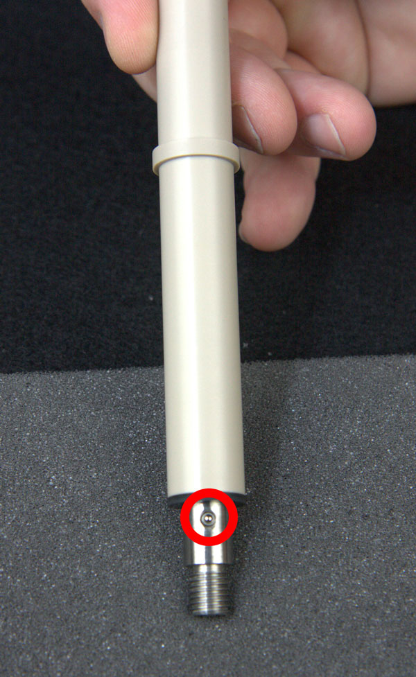
Figure 3. Spring-loaded ball plunger on LPR shaft.
-
- Counter
The counter electrode in an LPR experiment is usually a rod of either graphite or a type of stainless steel, such as hastelloy. Most of the troubleshooting that may be necessary in an LPR experiment with respect to the counter electrode is the same as for any other solution-phase electrochemistry test. For example, the counter electrode may be in an isolation tube separated by a frit from the main electrolyte. If this is the case, it is crucial to make sure solution is poured on both sides of the frit and the frit is not blocked so that the counter electrode has connection with the other electrodes in the main electrolyte compartment.
Another consideration is if the LPR test involves two phases - both an aqueous and a non-aqueous/oil phase. Sometimes these kinds of tests are conducted where an oil phase is added to sit on top of the aqueous phase into which the electrodes are physically contacting. In this type of experiment, if the counter electrode must be dipped down through the oil phase to reach the aqueous phase, a film of oil can form over the electrode and block or partially impede the aqueous phase electrode-electrolyte interface. It may be necessary to monitor whether this kind of film is adding noise to the LPR data when performing an experiment of this nature. If the oil film is formed when using a fritted isolation tube in particular, thus blocking the frit, then the counter electrode should be inserted directly into the main electrolyte without the use of the fritted isolation tube.
-
- Reference
The reference electrode in an LPR test is typically either a standard reference couple, such as Ag/AgCl or calomel, or a pseudo-reference that is a relatively non-polarizable metal like stainless steel (e.g., hastelloy).
It is somewhat common that the reference electrode is the source of error in an electrochemistry experiment. This can be a result of a blocked or partially blocked frit (if using a standard Ag/AgCl reference couple), drifting or unsteady reference potential (if using a pseudo or non-aqueous reference), contaminated inner fill solution and/or reference couple, or high impedances/stray capacitances to name a few ways the reference electrode may introduce error.
One other specific consideration regarding the reference electrode is when a Luggin capillary is used. The opening of a Luggin capillary is a very small OD hole and it can become easily blocked by a gas bubble, particularly in LPR tests conducted at high temperature due to solvent evaporation. In these cases, it may be wise to avoid using a Luggin capillary entirely.
The researcher is also encouraged to read additional Pine Research Knowledgebase articles, including Reference Electrode Storage and Master Reference Electrodes
Reference Electrode Storage and Master Reference Electrodes
and our Non-Aqueous Reference Electrode Overview
Non-Aqueous Reference Electrode Overview
.
- Cells and Accessories
LPR tests are normally conducted in a large glass vessel that holds up to 1 L electrolyte volume. Pine Research offers four varieties of this kind of cell: a basic version, one with a water jacket, one with a drain valve, and one with both a water jacket and drain valve (see Figure 4 for images of all four cells).
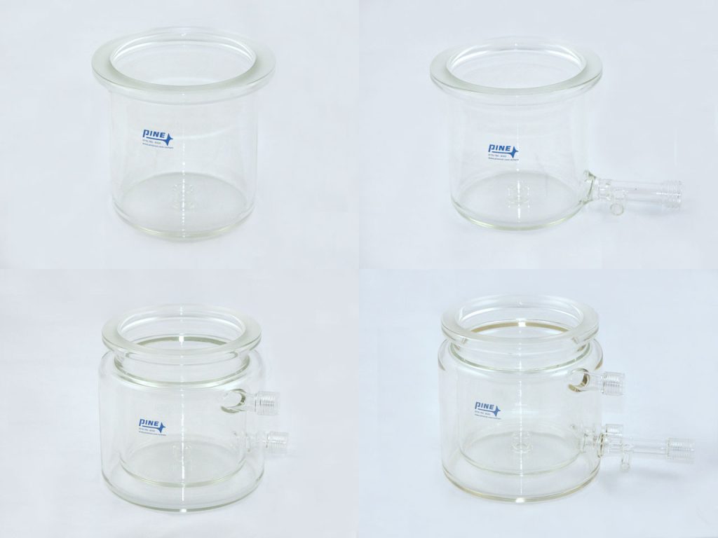
Figure 4. LPR 1 L cell options with and without drain valve and water jacket.
All four cell options contain roughly the same internal compartment dimensions, meaning the experiment is functionally and physically similar no matter which cell is being used. The presence of a drain valve on the corrosion cell is convenient for emptying the electrolyte after testing, as it may not be necessary to move the cell from its test location. In these cases, however, the trade-off may be that the rinsing and cleaning of the cell between tests is less rigorous compared to a cell that can be moved to a sink and physically scrubbed. The researcher may need to choose which convenience is most important for their specific experiments - that is, a more thoroughly rinsed and cleaned cell (that may be difficult to re-position and re-align for each subsequent test) or a more consistently positioned and aligned cell (that may be perhaps less thoroughly cleaned between tests from the previous electrolyte).
When elevated temperatures are needed (up to 80°C is permitted), the cell can be placed on a hot plate, in a heating mantle, or a water jacketed version can be used. In these cases, it is important to recognize that accessories and components may wear and degrade quicker than for LPR tests being conducted purely at room temperature. It may be necessary to routinely change out items like Viton O-rings more often when performing high temperature experiments frequently.
Other accessories that may be used in an LPR experiment that can introduce noise or error include a Luggin capillary for the reference electrode, fritted isolation tube for the counter electrode, and a gas inlet. As noted in the previous section on reference electrodes, the Luggin capillary can sometimes cause problems because of the small diameter opening at the bottom (see Figure 5 below for photo of a Luggin capillary used in LPR experiments). Particularly during high temperature LPR tests, it is possible for gas bubbles to form and block this narrow opening, causing a severe electrochemical error to occur due to a lack of solution communication between reference and working electrodes. In general, the use of a Luggin capillary can be beneficial in some situations as a means to decrease the impedance between working and reference electrodes. However, in many corrosion tests a brine solution of sufficiently large salinity is used such that the use of a Luggin capillary may be unnecessary. It is therefore suggested that in cases where a reduction in reference electrode impedance is not necessarily needed, the use of a Luggin capillary should be avoided.
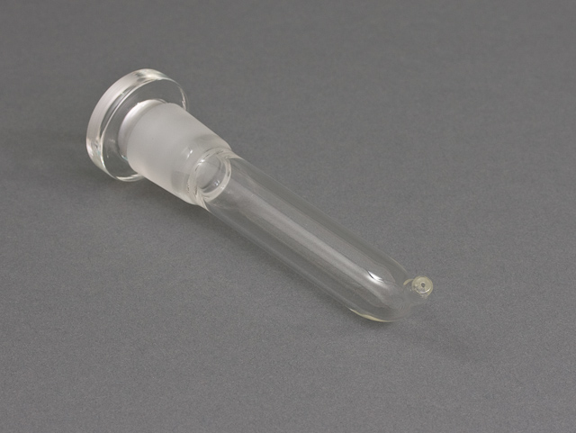
Figure 5. Reference electrode Luggin capillary.
The use of an isolation tube for the counter electrode, as noted above in the counter electrode section, can be problematic (see Figure 6 below). Occasionally, researchers do not pre-fill the isolation tube with main electrolyte solution before adding the counter electrode, instead either forgetting entirely or assuming backflow through the frit will fill it up. Backflow can be very slow and it is possible not enough solution may be present at the time of testing, so the potentiostat circuit will be incomplete and the LPR experiment will be a failure. Additionally, if the counter electrode is inserted and sealed, it can create trapped air that will not allow backfilling at all. Finally, if the frit is blocked or partially blocked, it can interfere with the experiment and add noise. In many cases, it may be recommended to avoid using an isolation tube for the counter electrode to prevent any such problems from arising.
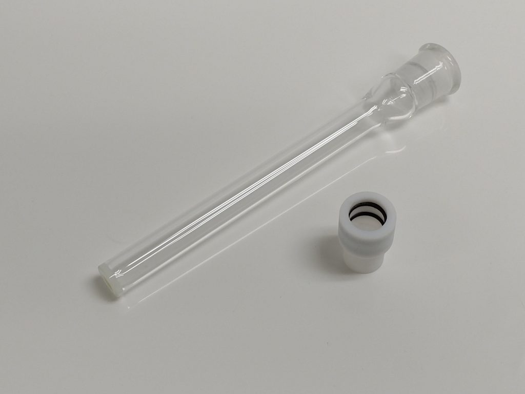
Figure 6. Counter electrode isolation tube.
The use of a gas inlet is often required for LPR experiments. Sometimes an inert gas like argon or nitrogen must be bubbled in solution for 45-60 minutes prior to testing to remove any dissolved oxygen. Other times carbon dioxide is bubbled to acidify the solution to simulate conditions experienced in the field where corrosion is more readily induced. In these cases, a gas purging/sparging inlet can be used (see Figure 7). The main considerations involved with using this accessory are that bubbles can traverse any of the electrodes or other accessories, partially blocking their access to electrolyte. When this occurs, noise is almost guaranteed in the electrochemical data. To prevent this, it is advisable to bubble near the top of the solution, or in the head space above the solution, while the test is running to reduce the chance that bubbles will impede the experiment progress.
Another source of noise common in a corrosion laboratory is caused by poor electrical connection between alligator clips from the cell cable and the terminal end of an electrode, either counter or reference. Often, poor connection can be caused by a rusty alligator clip. Those clips should be replaced as soon as they show any signs of corrosion or damage.
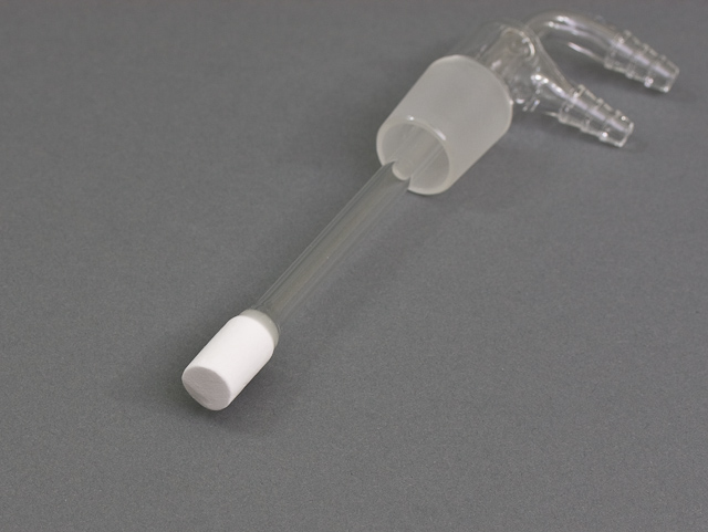
Figure 7. Gas purging/sparging inlet.
3Troubleshooting Noise with Potentiostat Software
A great deal of software troubleshooting with LPR experiments involves trial and error. There are many steps involved throughout a typical LPR experiment, including various types of OCP and rest periods. These steps can serve multiple purposes, including stabilizing the cylinder electrode for better LPR data and also spacing out the test when multiple iterations are conducted and must be separated by defined periods of time (e.g., taking LPR measurements every hour for 16 hours). Figure 8 shows an example flow diagram for an LPR experiment in AfterMath:
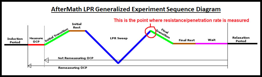
Figure 8. AfterMath LPR experiment flow diagram.
Beyond adjusting the myriad parameters shown in Fig. 8, there are a couple additional software settings that can be applied that may help improve the quality and consistency of LPR results. First, on the Filters tab of an LPR experiment, the default setting for all filters is normally "Automatic." In many situations, it is suggested to adjust the bottom-left two filters on this tab, the "Potential Response Filter (K1)" and "Current Response Filter (K1)," to "Manual" from the Filter Mode dropdown (see Figure 9). There is a dropdown for each filter's Cutoff Frequency that populates with a handful of hardware filter options specific to the instrument currently connected. However, it is not required to use these pre-filled values, and any different value can be entered to apply a software filter at that frequency to the data. In LPR experiments, it is suggested to use a value no lower than 1 Hz, and likely no higher than 10 Hz. This is an ideal range because smaller response filters may overly filter and distort the data, while the upper limit is still beneath the characteristic 50/60 Hz noise that accompanies most AC Mains systems in most countries.
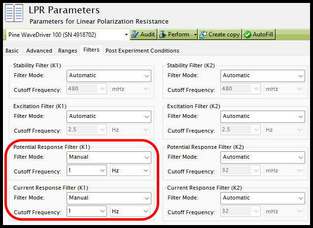
Figure 9. AfterMath LPR filter settings.
Finally, the last software setting that can be adjusted to try and help improve LPR data is located under "My Profile" at the bottom left of the screen, then under the "Instruments" tab in the main AfterMath window (see Figure 10). In the group "Circuit filters," the IR capacitance is set to None by default but can be changed if desired. It is suggested to first try the smallest setting, "Minimum (100nF)," as this will have the least impact on the data compared with the default setting of None, then step-wise iterate through the available IE capacitance filters to see if it has any impact on the LPR data. Note: it is important to return the IE capacitance setting back to "None" if LPR tests are finished and other electrochemistry experiments are to be conducted, as this filter could more heavily alter subsequent tests if the users are not aware it is not in its default status.
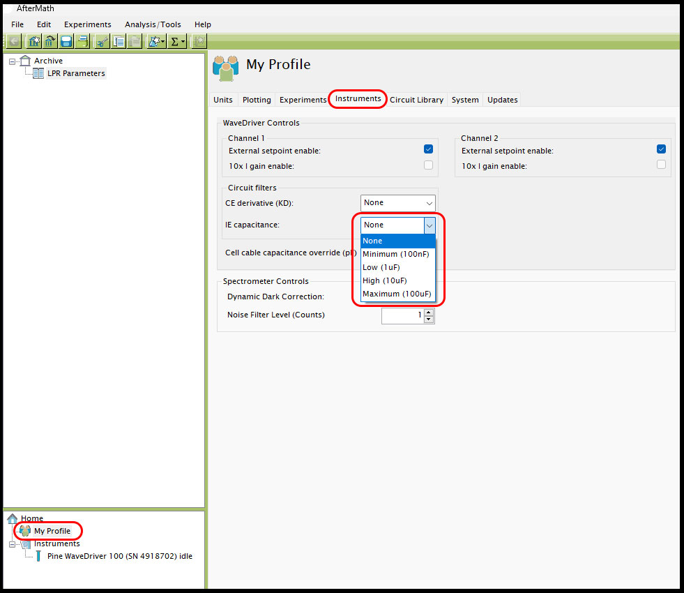
Figure 10. IE capacitance filter setting in AfterMath for LPR tests.