


This article describes a very fast way to test your WaveDriver potentiostat system. By connecting the potentiostat to a well behaved network of resistors and capacitors (known as a “Dummy Cell”), the potentiostat circuitry can be tested to assure that it is working properly.
Cyclic Voltammetry
This section describes how to set up AfterMath and the WaveDriver to perform cyclic voltammetry. Step-by-step instructions are provided below.
Step 1
Login to the AfterMath software (which you should have previously installed on your computer).
Installation instructions may be found here.

Step 2
Connect the WaveDriver Potentiostat to your computer using a USB cable.

Step 3
Connect the power supply to the potentiostat and then connect the power supply to power source (wall outlet) using an appropriate power cord. Note that Pine offers a variety of international power cords for use around the world, and the power supply is compatible with power sources ranging from 100 to 240 VAC (50 or 60 Hz).


Step 4
Turn on the potentiostat using the front panel power switch and wait for the WaveDriver to appear in the AfterMath Instrument List (see below).

Step 5
Check the status light on the WaveDriver Potentiostat. It should be green, indicating that the potentiostat is idle. The USB indicator light should flicker occasionally.

Step 6
Connect one end of the cell cable to the front panel of the WaveDriver. Connect the other end to the universal dummy cell (use cell “B” as shown below). Connect the black banana plug on the cell cable to the chassis ground connector on the dummy cell. Connect all of the other banana plugs to the banana jacks with corresponding colors on the dummy cell. Note that the BLUE and VIOLET banana plugs are only found on the WaveDriver 20 Bipotentiostat cell cable. The WaveDriver 10 Potentiostat does not have the BLUE and VIOLET banana plugs.

Step 7
Examine the Instrument Status (see below). Initially, the status should indicate that the cell is in a “disconnected” state. If desired, you may use the controls to apply a known idle condition to the cell. In the example below, the instrument has been adjusted to idle in the potentiostat mode while applying +1.2 volts to the working electrode.

Step 8
Starting from the AfterMath Experiments menu, navigate to the Dual electrode methods sub-menu and select the Dual Electrode Cyclic Voltammetry (DECV) option from the experiment list. A new DECV experiment specification is created and placed in a new archive (see below). To configure the parameters properly, (1) first click on the “I Feel Lucky” button, then change the current ranges, (2) and (3), to the 1.0 mA range, and finally, (4) change the mode to “Window”.

Step 9
Select the Advanced tab. Set the Threshold to “None” under Sampling. If your version of AfterMath does not offer “None” as an option, enter zero.
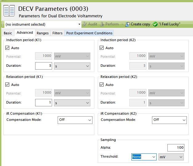
After setting threshold, return to the Basic tab.
Step 10
Choose the WaveDriver potentiostat in the drop-down menu (to the left of the “Audit” button). Then, press the “Perform” button to start the experiment.

Step 11
Monitor the progress of the experiment on the real time plot or the progress bar.

Step 12
When the experiment is finished, the results of the experiment are placed in a study folder in the archive. In addition to the main plot of the voltammogram, additional graphs are created in the “Other Plots” folder. The results are also available in tabular form.

![]() Note:
Note:
The diagonal traces in the plot above are not actual voltammograms. This slope of these traces represent the expected result for the resistance in the dummy cell circuit.
Using Your Own Electrochemical Cell
When you are ready to connect the cell cable to your own electrochemical cell, it is important to understand the signals associated with each of the seven banana plugs on the cell cable. Consult the following documentation describing the cell cable and how to connect the cell cable to various types of electrochemical cells:
![]() IMPORTANT NOTE:
IMPORTANT NOTE:
The WaveDriver working electrode connections feature separate working electrode DRIVE and SENSE lines. The SENSE and DRIVE lines are normally shorted together at a point near the electrochemical cell. This connection is quite easily accomplished by pushing the SENSE line banana plug into the back of the DRIVE line banana plug. Failure to short the DRIVE and SENSE lines together makes the potentiostat unstable and produces invalid results.
Additional Resources
Related Software Links: AfterMath Support Page, AfterMath User Guide, AfterMath Electrochemistry Guide, AfterMath Installation Guide
Related Hardware Links: WaveDriver 10 Potentiostat, WaveDriver 20 Bipotentiostat
Comments: