mobile-main-menu-button
Menu

Category Archives: Uncategorized

  • WaveNow and WaveNano: User Guide

    waveboth.jpg

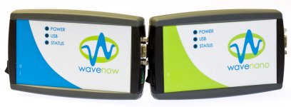
    Welcome to the User’s Guide for the WaveNow and WaveNano potentiostats offered by Pine Research Instrumentation. These instruments are general purpose potentiostats designed for those researchers and professors who need an affordable instrument suitable for routine electroanalytical methods such as cyclic voltammetry, square-wave voltammetry, differential pulse voltammetry and a variety of other potentiostatic and galvanostatic methods. Note that the WaveNow and WaveNano potentiostats are fully compatible with Pine’s AfterMath Data Organizer software.

    Related Links: Electrochemist’s Guide to AfterMath, AfterMath Support Site, WaveNow Support Site, WaveNano Support Site

    Read More
  • WaveDriver, WaveNow, and WaveNano Potentiostats: Device Driver

    USB Device Driver

    In order for the Microsoft Windows operating system on your computer to properly recognize a WaveDriver, WaveNow, or WaveNano potentiostat, certain device driver software must be installed on your system. This device driver software is a product developed by Future Technology Devices International, Ltd. (FTDI). The FTDI website features a driver download page from which the most recent “D2XX” driver can be obtained.
    As of February 2014, the most recent version (2.12.00) of the device driver is available for download as an executable file at the link below.

    Device Driver Installation Instructions

    In general, installation of the driver is a simple matter of downloading the driver package and clicking on the executable file.
    It may be necessary to choose the “Run as Administrator…” option when you attempt to execute the driver installer (see image).
    ftdi_installer.jpg

    If you need step-by-step instructions for installing the driver for a specific version of the Windows operating system, then consult the following web page to locate the appropriate installation guide for your computer:

    Activating the Device Driver

    To activate the device driver, your Windows system must “discover” the new instrument connected to your system.

    For the Pine WaveDriver, WaveNow, and WaveNano potentiostats, this discovery occurs when you turn on the potentiostat and connect it to your system via a USB cable. You should force your system to discover the potentiostat at a time when you are not running the AfterMath application. When you plug in the potentiostat for the first time, you will see various messages from the Windows operating system indicating the discovery of new hardware.

    Only after Windows completes the task of configuring this new hardware should you run the AfterMath application. If the driver installation is successful, then the instrument should appear in the instrument list in the lower-left corner of the AfterMath screen.

    Read More
  • WaveDriver, WaveNow, and WaveNano Potentiostats: Firmware Upgrade

    wavedriver_001.jpg
    waveboth.jpg

    Step 1

    Contact Pine to download the new firmware. The firmware upgrade will be inside a ZIP file as shown below.

    firmware_download.jpg

    Step 2

    Open the ZIP file and copy the firmware package to the Windows desktop (see below).

    firmware_unpackage.jpg

    Step 3

    Double-click on the firmware package to launch the firmware update program (see below).
    Make sure that the AfterMath application is NOT running and press the OK button.

    firmware_launch.jpg

    Step 4

    Information about the firmware version is displayed for your review.
    Press the OK button to install the new firmware in the potentiostat (see below).

    firmware_confirm.jpg

    Step 5

    Wait for the firmware to be installed. This may take several seconds (see below).

    firmware_transfer.jpg

    Step 6

    After the firmware is installed, the potentiostat will reset and the process is complete.
    Note that the message “*** Receive timed out” (as shown below) is the normal response after the reset.
    A dialog box confirming success will also appear (see below).

    firmware_completed.jpg

    Step 7

    At this point, you can restart AfterMath and confirm that the correct firmware version has been installed (see below).

    firmware_check_version.jpg
    Read More
  • WaveNow, WaveNano, WaveNowXV Quickstart

    This article describes a very fast way to test your WaveNow (or WaveNano) potentiostat system. By connecting the potentiostat to a well behaved network of resistors (known as a “Dummy Cell”), the potentiostat circuitry can be tested to assure that it is working properly.

    Step 1

    Login to the AfterMath software (which you should have previously installed on your computer).

    aftermath_shortcut_login.jpg

    If AfterMath was not previously installed on your computer, installation instructions may be found at the link below.

    Step 2

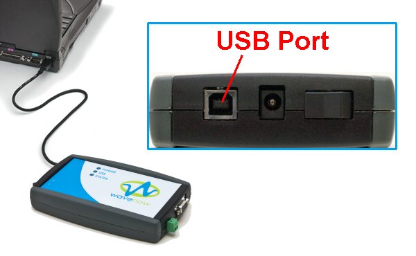
    Connect the WaveNow Potentiostat to your computer using a USB cable.

    wavenow_usb_connection.jpg

    Step 3

    Connect the power cord to the potentiostat and turn it on. Wait for the potentiostat to appear in the AfterMath Instrument List (see below).

    aftermath_stc_instrument_list.jpg

    Step 4

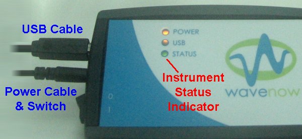
    Check the status light on the WaveNow Potentiostat. It should be green, indicating that the potentiostat is idle.

    wavenow_powered_idle.jpg

    Step 5

    Connect the Dummy Cell “C” to the potentiostat as shown below.

    dummy_cell_c.jpg

    Step 6

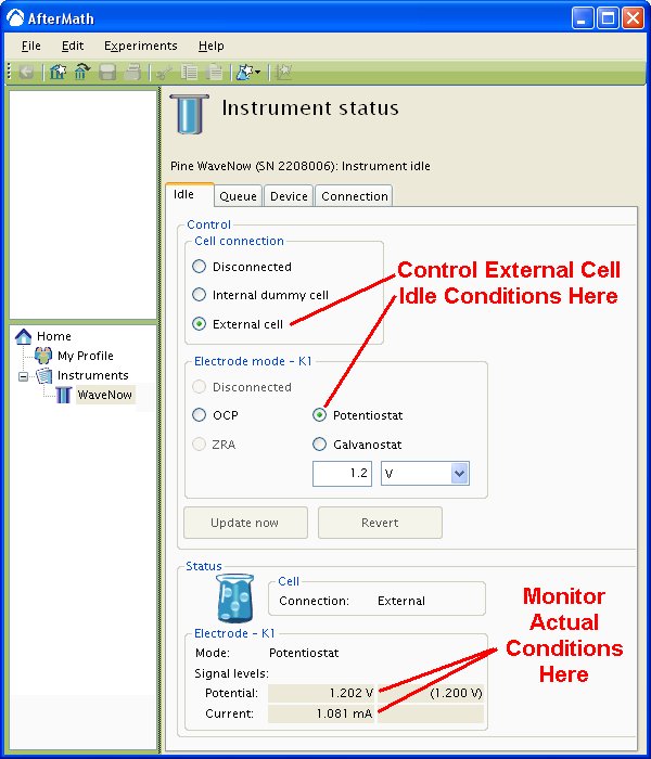
    Examine the Instrument Status (see below). Initially, the status should indicate that the cell is a “disconnected” state. If desired, you may use the controls to apply a known idle condition to the cell. In the example below, the instrument has been adjusted to idle in the potentiostat mode while applying +1.2 volts to the working electrode.

    aftermath_instrument_status_half.jpg

    Step 7

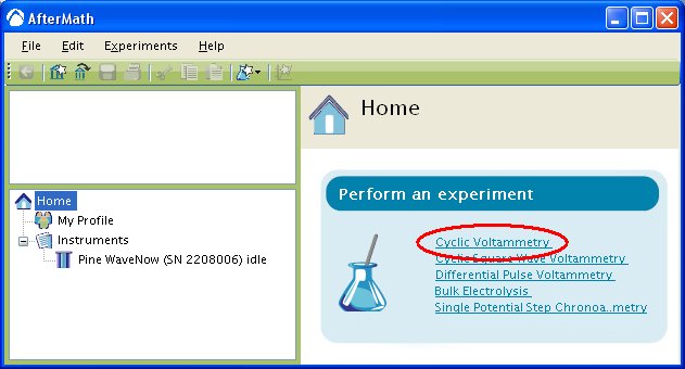
    From the AfterMath home page, select the “Cyclic Voltammetry” option from the experiment list (see below). (Alternately, you may choose “Cyclic Voltammetry” from the “Experiment” menu.) A new cyclic voltammetry experiment specification is created and placed in a new archive.

    aftermath_home_cv_start.jpg

    Step 8

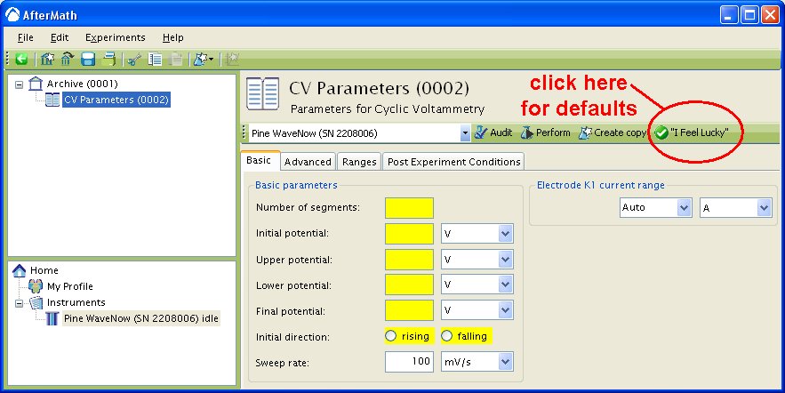
    Enter the required parameters describing the cyclic voltammetry experiment into the boxes which are shaded yellow. To use a set of default parameters, click on the “I Feel Lucky” button.

    aftermath_cv_spec.jpg

    Step 9

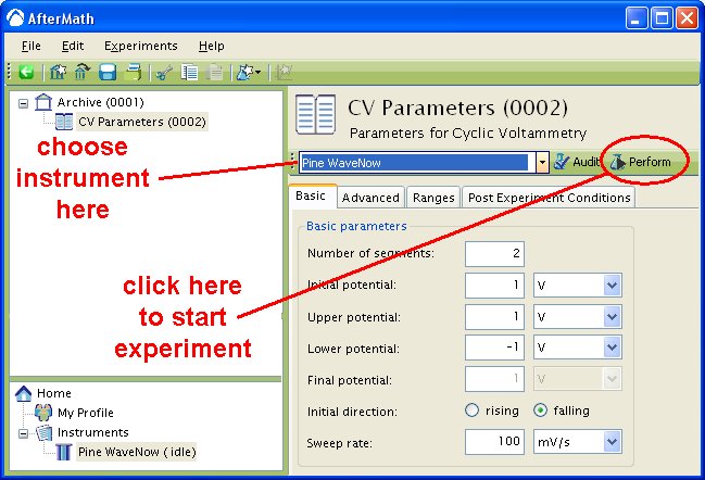
    Choose the WaveNow potentiostat in the drop-down menu (to the left of the “Audit” button). Then, press the “Perform” button to start the experiment.

    aftermath_perform_experiment.jpg

    Step 10

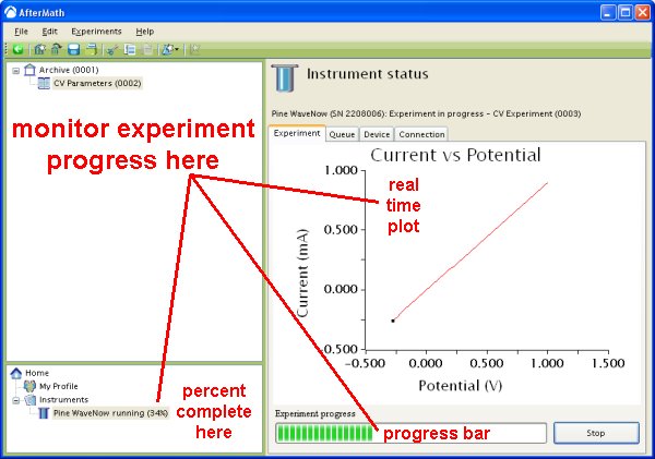
    Monitor the progress of the experiment on the real time plot or the progress bar.

    aftermath_monitor_experiment.jpg

    Step 11

    The results of the experiment are placed in a study folder in the archive. In addition to the main plot of the voltammogram, additional graphs are created in the “Other Plots” folder. The results are also available in tabular form.

    dummy_cell_c_voltammogram.jpg

      NOTE: The diagonal line in the plot above is clearly not an actual voltammogram. This pure ohmic response reflects the summed value of two series resistors on “Dummy Cell C” as follows: The charge transfer resistor (Rct) is nominally 1000 ohms, and the uncompensated resistor (Ru) is 100 ohms. Thus, the slope of the diagonal line reflects a combined nominal resistance of 1100 ohms. (The precise value of the summed resistance can be deduced from the inverse slope of the diagonal line. In this case the Rct + Ru value is 1099 ohms.)

    Step 12

    Using Your Own Electrochemical Cell: Physically connect the potentiostat to your electrochemical cell using an appropriate cell cable. One such cable is the Shielded Cell Cable (part number AKCABLE5, shown below).

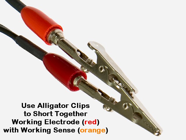
      The WaveNow and WaveNano potentiostats feature a working electrode SENSE line. This sense line (orange) should be connected to the working electrode at a point near the electrochemical cell. If you are using the Shielded Cell Cable , then this connection is quite easily accomplished by clipping the two alligator clips together as shown below.

    akcable5_004.jpg

    Step 13

    Using the Student Voltammetry Cell : If you are using a WaveNow or WaveNano potentiostat with Pine’s Student Voltammetry Cell, then use the special cable (part number RRTPE04) to directly connect from the cell port to the Student Voltammetry Cell.

    wavenow_003.jpg
    Read More
  • WaveNow User: Universal Cable

    Read More
  • WaveNow User: Template

    Read More
  • WaveNow: User Cable

    wavenow_tiny.jpg
    Note: This is one of many articles describing how to use the Pine WaveNow USB Potentiostat

    Read More
  • WaveNow User: Cell Port

    wavenow_tiny.jpg
    This article is part of the Pine WaveNow USB Potentiostat User's Guide

    Cell Port

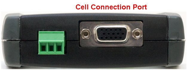
    The WaveNow USB Potentiostat is connected to an external electrochemical cell through a 15-pin cell port located on the side of the instrument. This port is a female HD-15 connector and has the same appearance as a VGA video connector on a personal computer.

    wavenow_cell_connection_port.jpg


    Pine offers several products designed to mate with the cell port on the WaveNow USB Potentiostat:

    • WaveNow/WaveNano Shielded Cell Cable Kit (part number AKCABLE5)
    • WaveNow/WaveNano Student Cell Cable for use with the Student Voltammetry Cell (part number RRTPE04)
    • Universal Dummy Cell for troubleshooting the potentiostat (part number AB01DUM1)
    • WaveNow Universal Cell Cable Kit (part number AKCABLE3) (discontinued)

    Note that some of the items listed above are sold separately.

    Pinout Information

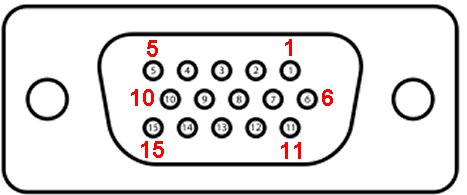
    Those users wishing to build their own cell cable for use with the WaveNow potentiostat should consult the pinout information listed in the table below. The color codes in the table refer to the standard Pine color code for electrochemical cell connections.

    wavenow_db15_pinout.jpg

    Pin
    1
    2
    3
    4
    5
    6
    7
    8
    9
    10
    11
    12
    1
    13
    14
    15

    Description
    reference electrode
    (shield for the reference signal)
    working electrode sense
    (shield for the sense signal)
    working electrode
    counter electrode
    (used for calibration)
    (used for calibration)
    reserved
    (working electrode signal shield)
    analog ground
    analog ground
    (used for calibration
    analog ground
    analog ground

    Color Code
    white
     
    orange
     
    red
    green


    black
    black
     
    black
    black

    Read More
  • WaveNow User: Dummy Cell

    wavenow_tiny.jpg
    This article is part of the Pine WaveNow USB Potentiostat User's Guide

    Dummy Cell Description

    A dummy cell is a simple circuit consisting of a few resistors and capacitors which can be used to test the behavior of a potentiostat. The WaveNow (and WaveNano) potentiostats are shipped with a circuit board which contains several dummy cell circuits, each of which can easily be connected to the potentiostat via the cell port (see photo below).

    ab01dum1_002.jpg ab01dum1_001.jpg

    The circuit board has four positions (“CELL A”, “CELL B”, “CELL C”, and “CELL D”).

    icon_info.jpgNOTE:

    The first position, “CELL A”, may be used for field verification of the instrument's calibration (along with the proper software and calibration instrumentation).

    icon_info.jpg NOTE:

    The circuit board included with the WaveNano potentiostat has a special position, “CELL E”, in place of “CELL B”. This special position offers a dummy cell with a one gigaohm resistor which is ideal for testing very low current behavior.

    Each of the dummy cell positions has the same basic circuit (see schematic diagram below), but they differ with respect to the exact resistor and capacitor values in the circuit. A table on the back side of the dummy cell lists the resistor and capacitor values, and this information is also available in the tabs below.

    narrow_schematic.jpg

    Cell B

    CDL = 100 µF
    RCT = 10 ohm
    RU = 10 ohm
    RUW = 1 ohm
    RREF = 1000 ohm
    RCTR = 10 ohm

    Cell C

    CDL = 1 µF
    RCT = 1000 ohm
    RU = 100 ohm
    RUW = 10 ohm
    RREF = 1×10⁴ ohm
    RCTR = 1000 ohm

    Cell D

    CDL = 10 nF
    RCT = 1×10⁶ ohm
    RU = 1×10⁴ ohm
    RUW = 1000 ohm
    RREF = 1×10⁵ ohm
    RCTR = 1×10⁵ ohm

    Cell E

    CDL = 100 pF
    RCT = 1×10⁹ ohm
    RU = 1×10⁶ ohm
    RUW = 1×10⁵ ohm
    RREF = 1×10⁶ ohm
    RCTR = 1×10⁶ ohm

    Typical Circuit Configurations

    By using various settings of the five dip switches, it is possible to test the potentiostat against a variety of different loads, each of which might mimic the load presented by a “real” electrochemical cell. In each configuration, the reference electrode is separated from the reference sense point (TP5, TP7, or TP9) by a resistor (Rref), and the counter electrode is also separated from this point by a resistor (Rctr, or solution resistance). Similarly, the working electrode is separated from the working sense point (TP6, TP8, or TP10) by a small resistor (Ruw). Note that Ruw value may be reduced to 0 by closing the switch DIP4, and Rref and Rctr may be reduced by joining the reference and counter electrodes together by closing the DIP1 switch.

    There are three configurations that are most useful for testing the behavior of a potentiostat (see table below). Note that the original factory settings for the dip switches correspond to the Randle's Circuit configuration.

    Standard Dip Switch Positions

    Dummy Cell Dip Configurations

    Pure Resistive Load
    DIP1 – open
    DIP2 – closed
    DIP3 – closed
    DIP4 – open
    DIP5 – open

    Pure Capacitive Load
    DIP1 – open
    DIP2 – closed
    DIP3 – open
    DIP4 – open
    DIP5 – closed

    Randle’s Circuit
    DIP1 – open
    DIP2 – open
    DIP3 – closed
    DIP4 – open
    DIP5 – closed

    icon_info.jpgNOTE:

    If you are unfamiliar with dip switches, it can be difficult to discern whether a switch is closed or open. The photograph above shows examples of both a closed switch and an open switch.

    Pure Resistive Load

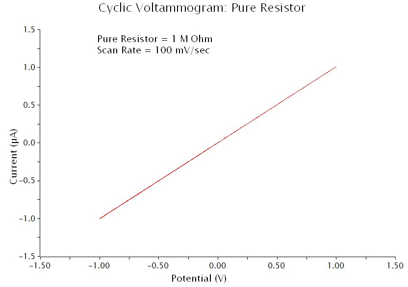
    The most basic configuration is Pure Resistive Load, where a resistor is used to mimick the charge transfer resistance (Rct) at the electrode/electrolyte interface. A cyclic voltammogram obtained using this dummy cell configuration should show straight line with the slope inversely proportional to the Rct resistance (see below).

    pure_resistive_loading.jpg

    Pure Capacitive Load

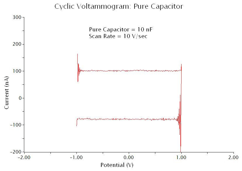
    A Pure Capacitive Load is used to simulate an electrode double layer that is ideally polarizable. The charging current, iDL, observed when using this capacitive load is given by the following equation,

    iDL = CDL v

    where the capacitance, CDL, mimicks the double-layer capacitance, and the working electrode potential is being swept at a constant rate, v. Very small charging currents can be produced using lower sweep rates. This is useful when evaluating a potentiostat's ability to measure small currents. An example “voltammogram” obtained using the Pure Capacitive Load configuration is shown below.

    pure_capacitive_loading.jpg


    Note how the “voltammogram” appears as a rectangular box, and the height of the box (along the vertical axis) is twice the value of the charging current calculated according to the above equation. The oscillations at points where the sweeping potential suddenly switches direction are quite noticable when using a pure capacitive load. Most “real” electrochemical cells are less prone to exhibiting such oscillations.

    Randle’s Circuit

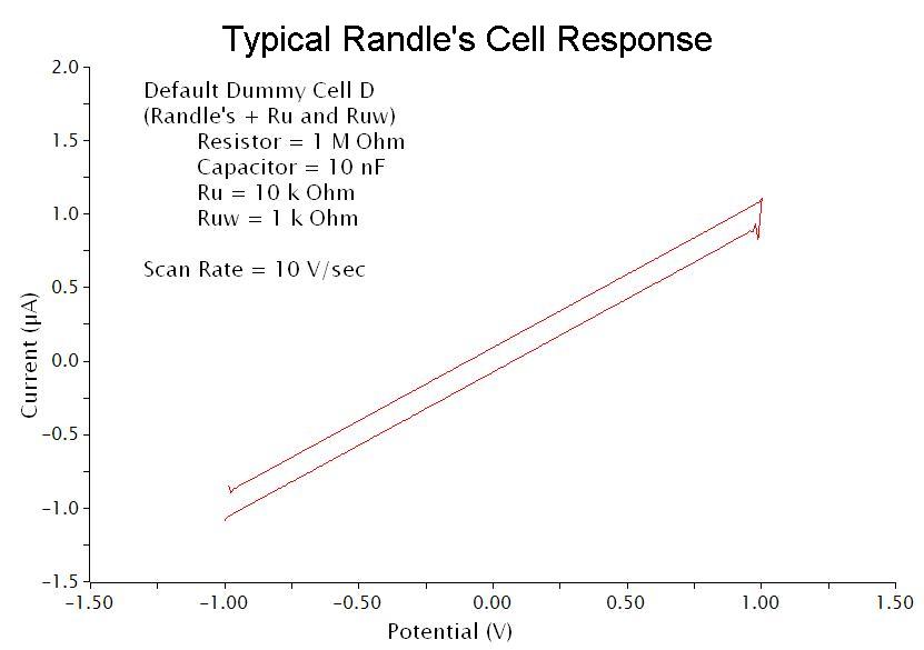
    A Randle's circuit places the the double-layer capacitance (Cdl) in parallel with the charge transfer resistance (Rct) and another impedance element known as a Warburg element. The Warburg element cannot be simulated using simple resistors and capacitors because it represents the “real” diffusion processes which occur in an actual solution in an electrochemical cell.

    The Randle's Circuit configuration for the dummy cell omits the Warburg element, but includes the parallel double-layer capacitance and charge transfer resistance. The response from this pseudo-Randle's cell is shown below.

    randles_cell_loading.jpg

    Ordering Information

    Part numbers are provided below.

    Part Number
    AB01DUM1
    AB01DUM2

    Description
    Dummy cell for the WaveNow potentiostat
    Dummy cell for the WaveNano potentiostat

    The Dummy Cell can be viewed and purchased from Pine Research Instrumentation at the provided link

    Read More
  • WaveNow User: Introduction

    wavenow_tiny.jpg
    This article is part of the Pine WaveNow USB Potentiostat User's Guide

    Scope of this Guide

    This User's Guide describes the basic functions of the WaveNow USB Potentiostat, including product specifications and limitations, product warranty, proper electrical connections, and other technical information.

    A portion of this guide is dedicated to the subject of using Pine's AfterMath software to control the WaveNow USB Potentiostat and to analyze data acquired using the instrument. The reader of this manual is also expected to become familiar with the use of the AfterMath software by reading the AfterMath Data Organizer User's Guide.

    This guide is written for the professional scientist or engineer (or student of science and engineering) and assumes a basic knowledge of scientific measurement and data presentation. Portions of this manual devoted to electrochemical concepts assume some familiarity with the subject of electrochemistry.

    Read More