


1Abstract
2Introduction
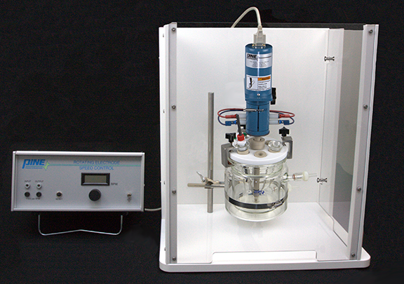
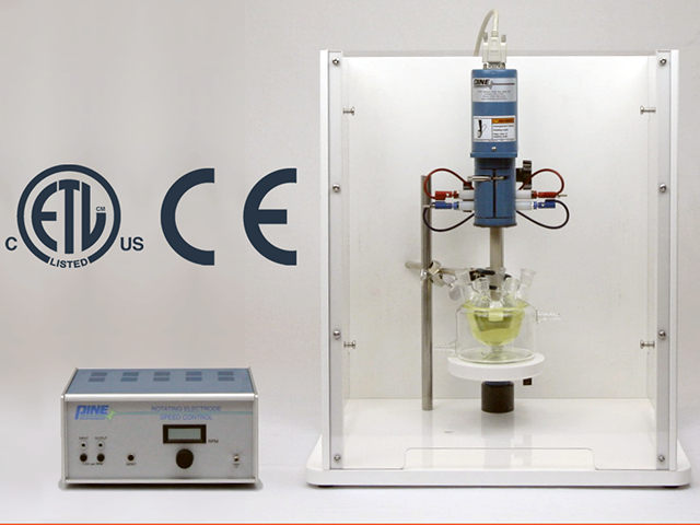
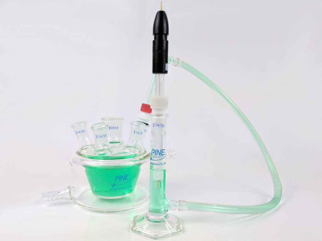
Figure 1. Typical Rotating Cylinder Setup for Corrosion Analysis
- An analytical electrode rotator (Pine Research MSR Electrode Rotator,
 Modulated Speed Rotator (MSR)
part number AFMSRCE). The rotator sets the rotation rate of the RCE cylinder (coupon).
Modulated Speed Rotator (MSR)
part number AFMSRCE). The rotator sets the rotation rate of the RCE cylinder (coupon). - A shaft to hold the RCE cylinder (part number AFE9MBA)
 Precision 15 mm Single RCE Shaft
and connect electrically through the rotator to the potentiostat where corrosion rate can be measured.
Precision 15 mm Single RCE Shaft
and connect electrically through the rotator to the potentiostat where corrosion rate can be measured. - RCE cylinder inserts (coupon)
 15 mm OD Cylinder Inserts
that have a 3 cm2 exposed area and are made from the specific metal of interest.
15 mm OD Cylinder Inserts
that have a 3 cm2 exposed area and are made from the specific metal of interest. - An OpenTop glass cell
 OpenTop Cell with Water Jacket
that integrates easy access for purge gas control, as well as insertion and positioning of other electrodes (counter and reference) and accessories.
OpenTop Cell with Water Jacket
that integrates easy access for purge gas control, as well as insertion and positioning of other electrodes (counter and reference) and accessories. - A manner by which to control temperature, commonly a water jacket around the glass electrochemical cell or directly by means of a hotplate beneath the glass cell.
- A potentiostat to measure and record corrosion current.
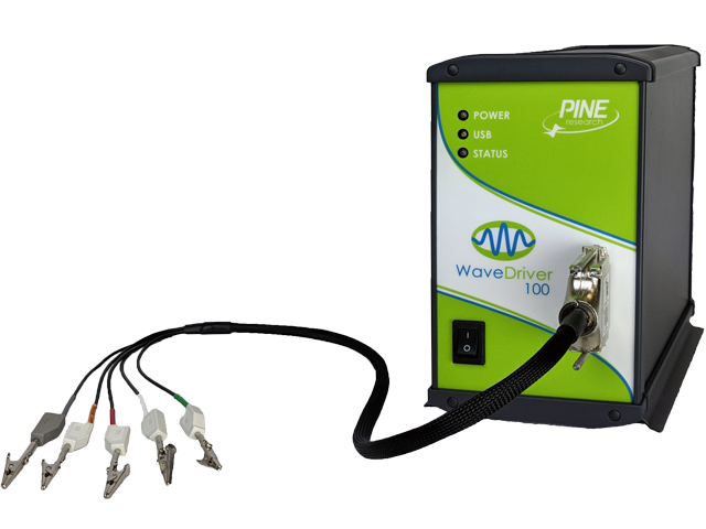 WaveDriver 100 EIS Potentiostat/Galvanostat
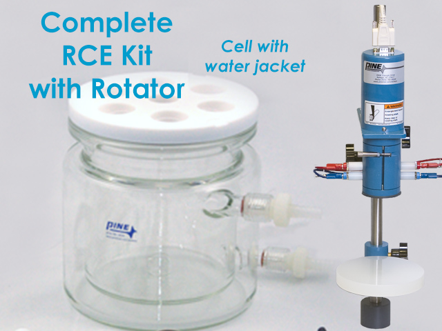 Complete RCE Bundle with Rotator and Jacketed Cell
This guide mirrors the website and product selection is detailed in the flow chart provided (see Figure 2).
Complete RCE Bundle with Rotator and Jacketed Cell
This guide mirrors the website and product selection is detailed in the flow chart provided (see Figure 2).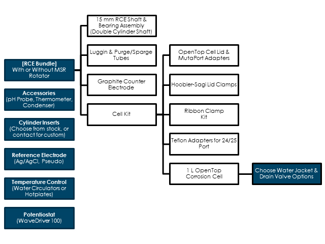
Figure 2. Flow of Products for a Complete 15 mm RCE Setup. User Input Required at Shaded Boxes
315 mm RCE System Bundles
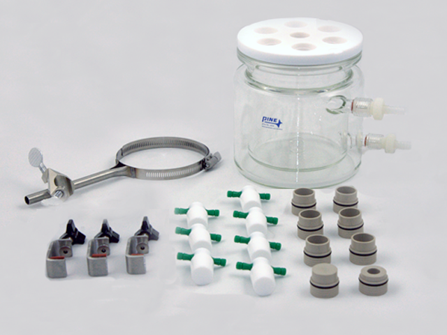
- Cell kit, which contains the OpenTop cell and components (OpenTop cell lid, adapters, ribbon clamp, cell clamps, and PTFE stoppers). There are four different cell kits available (all cells are 1 L volume and compatible with the 15 mm RCE accessories):
- Jacketed cell with drain valve (part number AFCELL8)
 OpenTop Cell with Water Jacket and Drain Valve
- Jacketed cell without drain valve (part number AFCELL8U3)
OpenTop Cell with Water Jacket
- Basic (unjacketed) cell with drain valve (part number AFCELL8U)
 OpenTop Cell with Drain Valve
- Basic (unjacketed) cell without drain valve (part number AFCELL8U2)
 OpenTop Cell
- Jacketed cell with drain valve (part number AFCELL8)
- Hose barb/drain valve accessories are included as appropriate for the chosen cell
- 15 mm single cylinder RCE shaft (part number AFE9MBA)
Precision 15 mm Single RCE Shaft
with gas-purged taper plug assembly (part number AC01TPA6M)
 Gas-Purged Bearing Assembly
- Graphite counter electrode (part number AFCTR3)
 Large Graphite Counter Electrode Assembly
- Luggin capillary (part number RRPG031)
 Luggin Tube
for reference electrode (reference electrode not included)
Luggin Tube
for reference electrode (reference electrode not included)
 Standard Size Reference Electrodes
- Dual port gas purge/sparge accessory (part number RRPG034)
 Dual Port Gas Inlet, 24/25
| Bundle Code/ Part Number |
Description |
[RCE15-JV]
 RCE Bundle with Jacketed Cell with Drain Valve
|
15 mm RCE Bundle - jacketed cell with drain valve Includes cell kit: AFCELL8
OpenTop Cell with Water Jacket and Drain Valve
|
[RCE15-RJV]
 Complete RCE Bundle with Rotator and Jacketed Cell with Drain Valve
|
15 mm RCE Bundle - jacketed cell with drain valve, includes rotator
Modulated Speed Rotator (MSR)
Includes cell kit: AFCELL8
OpenTop Cell with Water Jacket and Drain Valve
|
[RCE15-J]
 RCE Bundle with Jacketed Cell
|
15 mm RCE Bundle - jacketed cell without drain valve Includes cell kit: AFCELL8U3
OpenTop Cell with Water Jacket
|
| [RCE15-RJ]
Complete RCE Bundle with Rotator and Jacketed Cell
|
15 mm RCE Bundle - jacketed cell without drain valve, includes rotator
Modulated Speed Rotator (MSR)
Includes cell kit: AFCELL8U3
OpenTop Cell with Water Jacket
|
[RCE15-V]
 RCE Bundle with Cell with Drain Valve
|
15 mm RCE Bundle - basic (unjacketed) cell with drain valve Includes cell kit: AFCELL8U
OpenTop Cell with Drain Valve
|
[RCE15-RV]
 Complete RCE Bundle with Rotator and Cell with Drain Valve
|
15 mm RCE Bundle - basic (unjacketed) cell with drain valve, includes rotator
Modulated Speed Rotator (MSR)
Includes cell kit: AFCELL8U
OpenTop Cell with Drain Valve
|
[RCE15-X]
 RCE Bundle with Basic Cell
|
15 mm RCE Bundle - basic (unjacketed) cell without drain valve Includes cell kit: AFCELL8U2
OpenTop Cell
|
[RCE15-R]
 Complete RCE Bundle with Rotator and Basic Cell
|
15 mm RCE Bundle - basic (unjacketed) cell without drain valve, includes rotator
Modulated Speed Rotator (MSR)
Includes cell kit: AFCELL8U2
OpenTop Cell
|
RCE Bundle with Jacketed Cell
product bundle is shown below (see Figure 3). The bundles are designed for the general case of most RCE users. Each individual component of a complete 15 mm RCE Corrosion System can be replaced and ordered individually.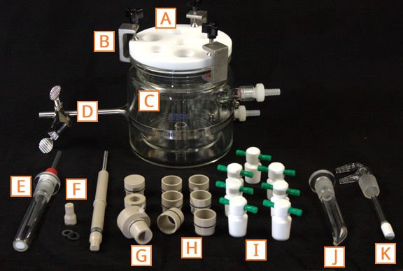 |
|
| Code | Description |
| A | PTFE OpenTop Lid |
| B | Hoobler-Sagi Lid Clamp (set of 3) |
| C | OpenTop Cell (user chooses configuration) |
| D | Ribbon Clamp and Cross Clamp |
| E | Graphite Counter Electrode (part number AFCTR3)
Large Graphite Counter Electrode Assembly
|
| F | 15 mm Single Cylinder RCE Shaft (part number AFE9MBA)
Precision 15 mm Single RCE Shaft
|
| G | Gas-Purged Bearing Assembly (part number AC01TPA6M)
Gas-Purged Bearing Assembly
|
| H | MutaPort Adapters for OpenTop Lid (1x cap, 1x 14/20, 6x 24/25) |
| I | PTFE Stoppers (set of 7) |
| J | Luggin Capillary Tube for Reference Electrode (part number RRPG031)
Luggin Tube
|
| K | Dual Port Gas Purge/Sparge Tube (part number RRPG034)
Dual Port Gas Inlet, 24/25
|
4Major RCE System Components
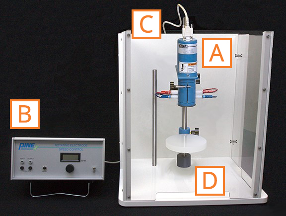
4.1Electrode Rotator
Modulated Speed Rotator (MSR)
(see Figure 4). The MSR Rotator is a major component of an RCE system. Briefly, the MSR Rotator consists of the following primary components:- A motor head, into which the 15 mm RCE shaft is installed
- A control box that connects to the motor head, with which rotation rate of the shaft/cylinder is controlled
- A cable to connect control box to motor head
- An AC power cable that connects to the control box
- Polymer base and enclosure, into which the motor and cell are installed on stainless steel support rods. The enclosure is secured by four metal posts on the walls
 |
|
| Code | Description |
| A | MSR Motor |
| B | MSR Control Box |
| C | MSR Control Cable (HD15) |
| D | Polymer Base and Enclosure |
 Standard 10 Amp Power Cords
Consult the website for a full list of power cords. You will specify the power cord needed by its part number at the time of order (please contact us with any special cord needs if you do not find the appropriate cord for your country).
Standard 10 Amp Power Cords
Consult the website for a full list of power cords. You will specify the power cord needed by its part number at the time of order (please contact us with any special cord needs if you do not find the appropriate cord for your country). 4.2Rotating Electrode Shaft for Cylinders and Bearing Assembly
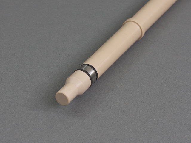
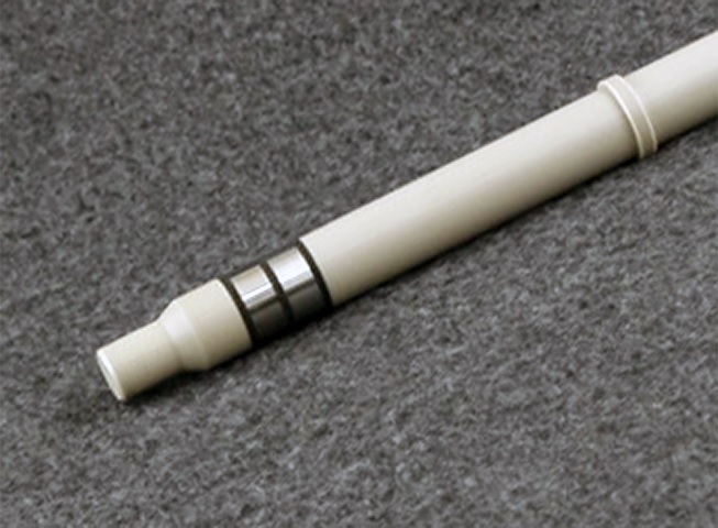
Precision 15 mm Single RCE Shaft
(see Figure 5) connects to the motor head on the ¼” stainless steel end. A metal cylinder insert (coupon) installs on the opposite end, and is electrically coupled to the shaft and then to the rotator brushes. The potentiostat working electrode cell cable connects to the top brush contact(s) on the MSR motor. This arrangement offers flexibility in RCE cylinder configuration. The RCE shaft body is made of polyether ether ketone (PEEK). PEEK is chemically compatible in a wide variety of solvent systems and can be used safely up to 80°C.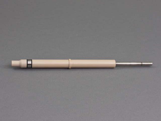
Figure 5. Single 15 mm Cylinder RCE Shaft (pictured with installed metal cylinder)
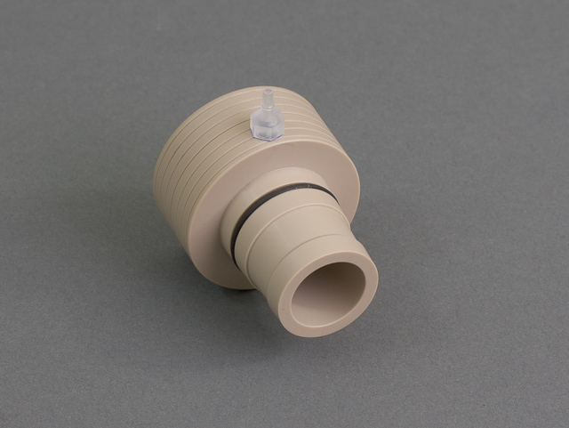
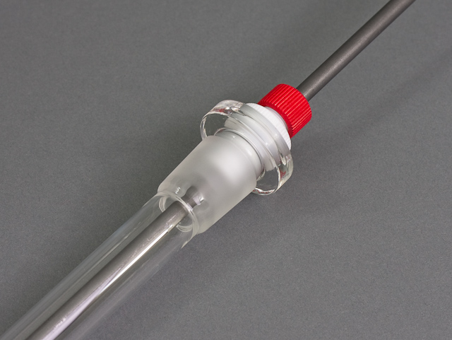
Gas-Purged Bearing Assembly
(see Figure 6) interfaces the shaft to the electrochemical cell and lid. It is precision-machined to fit the 15 mm RCE shaft body. It is made of PEEK and its bearings are ceramic to avoid corrosion. The bearing assembly has an inset fluoroelastomer rubber O-ring to create a seal and a gas purge barb at the junction of the assembly. The tapered assembly fits standard 24/25 or 24/40 tapered joints. The central hole in the corrosion cell OpenTop (see Figure 3) lid is a 24 mm opening, designed to accommodate the bearing assembly and RCE shaft. When all other ports of the cell are closed, a slight positive pressure can be maintained in the cell when the gas-purged bearing assembly is used.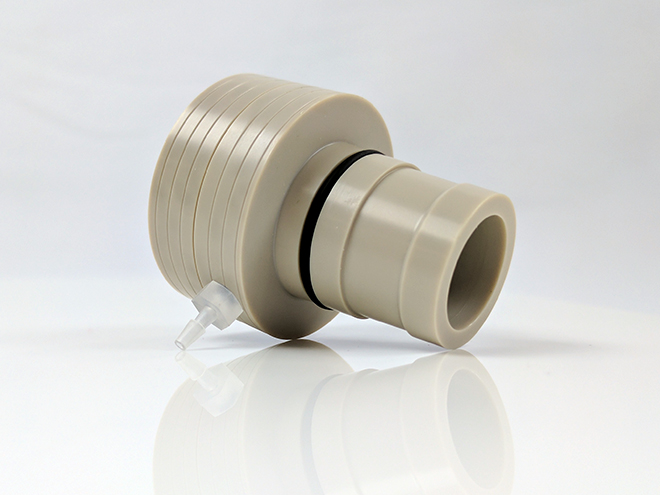
Figure 6. Gas-Purged Bearing Assembly for 15 mm RCE Setup
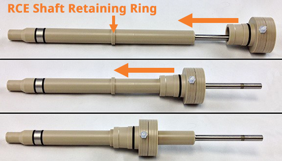
Figure 7. Installation of Gas-Purged Bearing Assembly onto Single Cylinder RCE Shaft
 Precision 15 mm Double RCE Shaft
(see Figure 8). The 15 mm RCE product bundles are sold with a single cylinder shaft by default. Please inform sales at the time of inquiry if you would instead like the double cylinder shaft or want to add it to your existing product bundle.
Precision 15 mm Double RCE Shaft
(see Figure 8). The 15 mm RCE product bundles are sold with a single cylinder shaft by default. Please inform sales at the time of inquiry if you would instead like the double cylinder shaft or want to add it to your existing product bundle.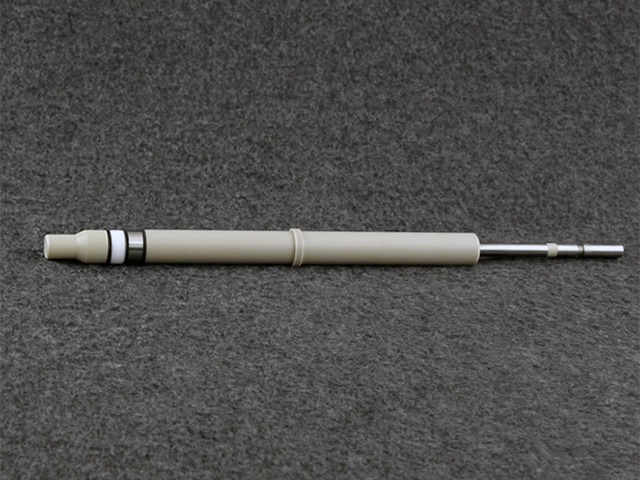
Figure 8. Double 15 mm Cylinder RCE Shaft (pictured with two installed cylinders)
15 mm OD Cylinder Inserts
are precision metal samples that fit the 15 mm single and double cylinder RCE shafts. To seal around a cylinder insert installed on the RCE shaft, flat fluoroelastomer washers are used in conjunction with a threaded PEEK nut on the shaft end (see Figure 9). A package of ten fluoroelastomer washers is included with each shaft. Additional washers are available (part number AKE9VWASHER).
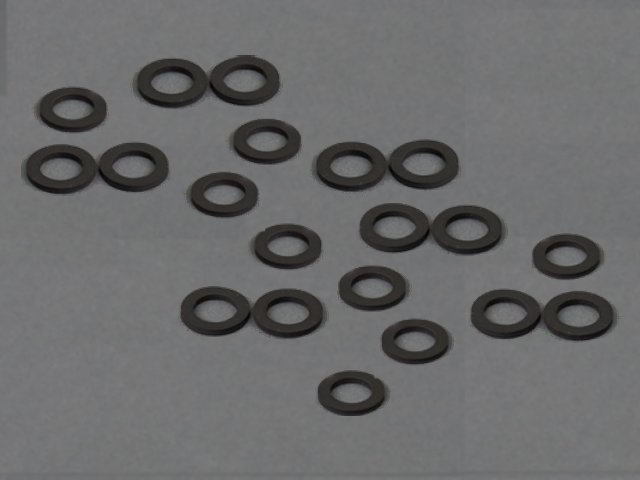 Fluoroelastomer Seal Washers
Washers should be replaced regularly with every other cylinder change to minimize solution leakage and edge corrosion around the cylinders.
Fluoroelastomer Seal Washers
Washers should be replaced regularly with every other cylinder change to minimize solution leakage and edge corrosion around the cylinders.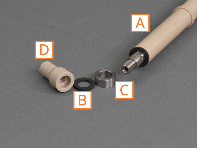 |
|
| Code | Description |
| A | 15 mm Single Cylinder RCE Shaft
Precision 15 mm Single RCE Shaft
|
| B | Fluoroelastomer Washer
Fluoroelastomer Seal Washers
|
| C | 15 mm OD Metal Cylinder Insert (Coupon)
15 mm OD Cylinder Inserts
|
| D | 15 mm RCE PEEK Nut |
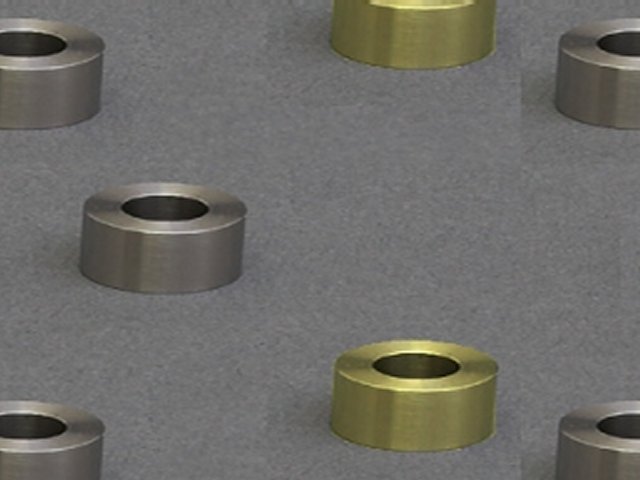
4.315 mm RCE Cylinder Inserts (Coupons)
15 mm OD Cylinder Inserts
(download from our website, also shown below in inches, see Figure 10) for users who choose to machine their own cylinder inserts. Pine Research can custom-fabricate cylinder inserts from almost any non-toxic material, including starting material sent by the customer. Inquire with sales to initiate custom cylinder inserts.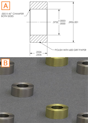
Figure 10. (A) Mechanical Drawing of 15 mm OD Cylinder Inserts; (B) Photo of 15 mm OD Cylinder Inserts
| Part Number | Description |
| AFE9C150G064S1X-10 | 15 mm OD Cylinder Inserts, 1018 Carbon Steel, Pack of 10 |
| AFE9C150G064T3X-10 | 15 mm OD Cylinder Inserts, 316/316L Stainless Steel, Pack of 10 |
| AFE9C150G064T5X-10 | 15 mm OD Cylinder Inserts, 430 Stainless Steel, Pack of 10 |
4.4OpenTop Corrosion Cell
- 1 L volume
- Fit PTFE OpenTop lid
- Made of borosilicate glass
- Designed specifically for the 15 mm RCE system shaft and MSR rotator
- Jacketed cell with drain valve (part number AFCELL8)
OpenTop Cell with Water Jacket and Drain Valve
- Jacketed cell without drain valve (part number AFCELL8U3)
OpenTop Cell with Water Jacket
- Basic (unjacketed) cell with drain valve (part number AFCELL8U)
OpenTop Cell with Drain Valve
- Basic (unjacketed) cell without drain valve (part number AFCELL8U2)
OpenTop Cell
 Water Circulator Kits
users can control the temperature of the internal solution. Threaded hose barbs are shipped with jacketed OpenTop cells. Alternatively, temperature in a basic, unjacketed cell can be controlled using a hot plate.
Water Circulator Kits
users can control the temperature of the internal solution. Threaded hose barbs are shipped with jacketed OpenTop cells. Alternatively, temperature in a basic, unjacketed cell can be controlled using a hot plate.
 Hotplate Kits
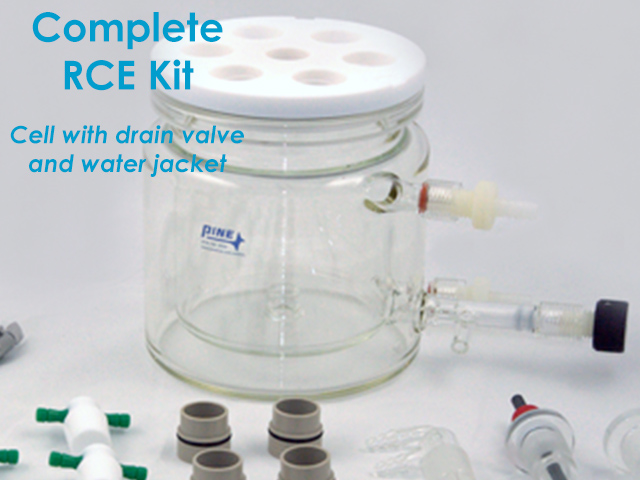
4.4.1Jacketed Cell with Drain Valve (AFCELL8)
OpenTop Cell with Water Jacket and Drain Valve
(part number RRPG122), included in the [RCE15-JV]
RCE Bundle with Jacketed Cell with Drain Valve
and [RCE15-RJV]
Complete RCE Bundle with Rotator and Jacketed Cell with Drain Valve
bundles, features a water jacket and drain (see Figure 11). Included with the water jacket and drain are the appropriate fittings (barbed hose connectors for the jacket and a threaded valve for the drain, see Figure 12).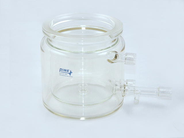
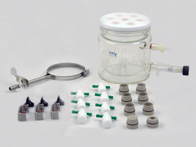
Figure 11. OpenTop Jacketed Cell with Drain Valve (part number AFCELL8)
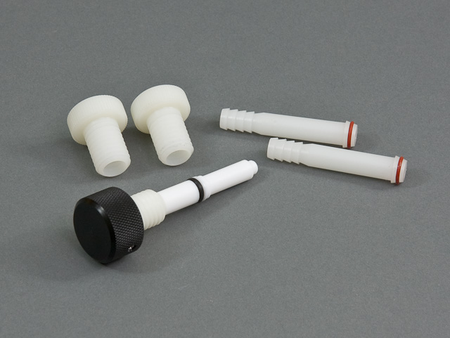
Figure 12. Threaded Barbed Hose Connectors and Drain Valve Stem with Knob
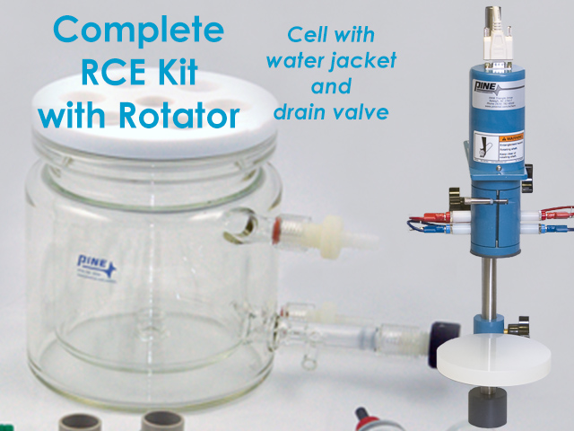
4.4.2Jacketed Cell without Drain Valve (AFCELL8U3)
OpenTop Cell with Water Jacket
(part number RRPG210), included in the [RCE15-J]
RCE Bundle with Jacketed Cell
and [RCE15-RJ]
Complete RCE Bundle with Rotator and Jacketed Cell
bundles, features a water jacket (see Figure 13). Included with the water jacket are the appropriate fittings (barbed hose connectors for the jacket, see Figure 12).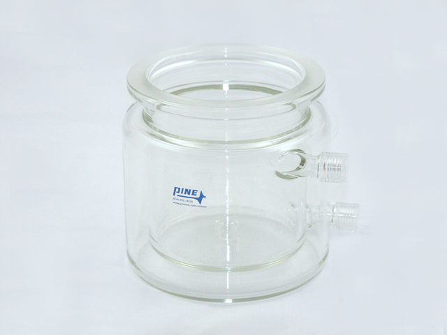
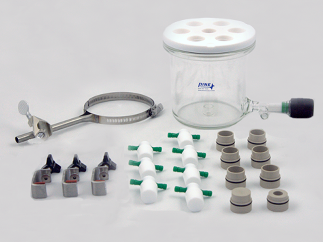
Figure 13. OpenTop Jacketed Cell without Drain Valve (part number AFCELL8U3)
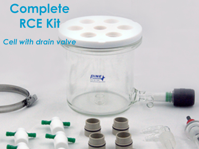
4.4.3Basic (Unjacketed) Cell with Drain Valve (AFCELL8U)
OpenTop Cell with Drain Valve
(part number RRPG143), included in the [RCE15-V]
RCE Bundle with Cell with Drain Valve
and [RCE15-RV]
Complete RCE Bundle with Rotator and Cell with Drain Valve
bundles, is a basic, unjacketed cell (see Figure 14) with drain valve (see Figure 15) that integrates with the other components of the 15 mm RCE system.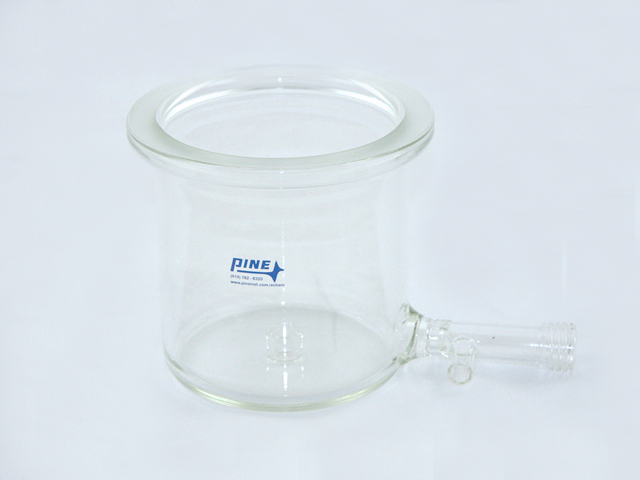
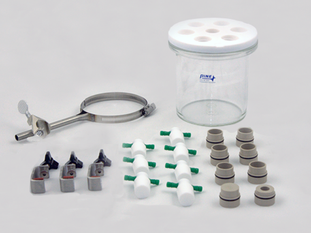
Figure 14. OpenTop Basic (Unjacketed) Cell with Drain Valve (part number AFCELL8U)
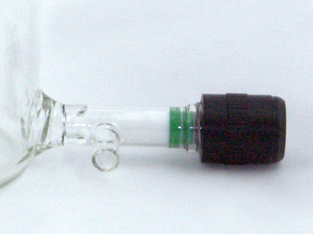
Figure 15. Threaded Drain Valve Stem with Knob
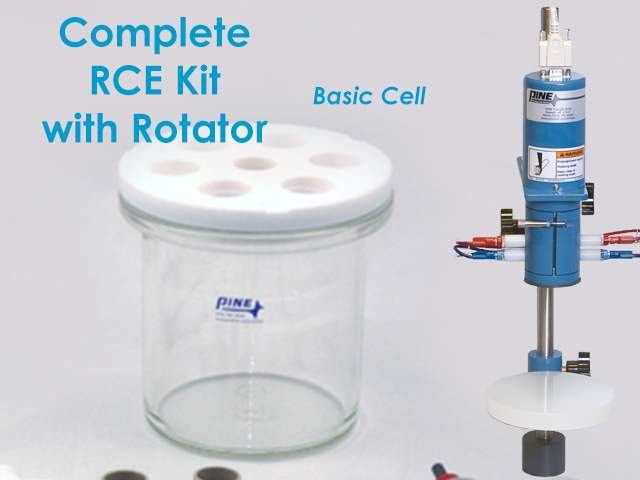
4.4.4Basic (Unjacketed) Cell without Drain Valve (AFCELL8U2)
OpenTop Cell
(part number RRPG173), included in the [RCE15-X]
RCE Bundle with Basic Cell
and [RCE15-R]
Complete RCE Bundle with Rotator and Basic Cell
bundles, is a basic cell that integrates with the other components of the 15 mm RCE system (see Figure 16).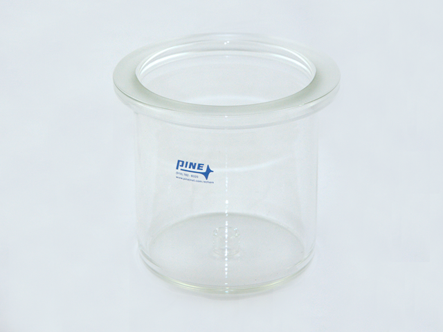
Figure 16. OpenTop Basic (Unjacketed) Cell without Drain Valve (part number AFCELL8U2)
4.5Accessories Included with 15 mm Corrosion Cell
| Part Number | Description | Quantity |
| AC01LID122 | OpenTop Cell Lid, PTFE | 1 |
| AC01CLP1 | Hoobler-Sagi Cell Clamps | 3 |
| AKCLAMP2 | Ribbon Clamp and Cross Joint | 1 |
| AFCTR3 | Graphite Counter Electrode Assembly | 1 |
| AFE9MBA | 15 mm Single Cylinder RCE Shaft | 1 |
| AC01TPA6M | Gas-Purged Bearing Assembly | 1 |
| AC01APLUG | MutaPort Adapter, Plug | 1 |
| AC01A1420 | MutaPort Adapter, 14/20 Port | 1 |
| AC01A2425 | MutaPort Adapter, 24/25 Port | 6 |
| RRPG085K1 | PTFE Stoppers, 24/25 Joint | 7 |
| RRPG031 | Luggin Capillary (24/25 outside, 14/20 inside) | 1 |
| RRPG034 | Dual-Port Purge/Sparge Accessory | 1 |
4.6Optional Accessories for 15 mm Corrosion Cell
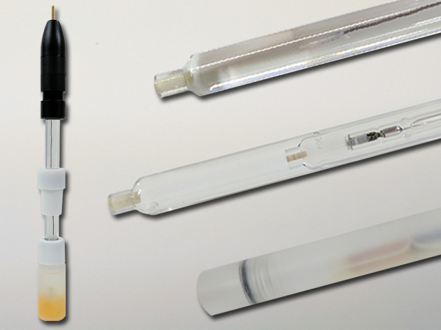
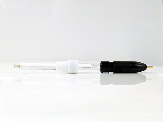
4.6.1Reference Electrodes
Standard Size Reference Electrodes
- Standard size reference electrodes have a 9.5 mm OD body and come with a PTFE adapter that only fits into a 14/20 port
- Standard size reference electrodes are compatible with the included Luggin capillary (part number RRPG031)
Luggin Tube
- Only two standard size reference electrodes can be shipped along with the other items in a 15 mm RCE corrosion product bundle: the Single Junction Ag/AgCl Reference Electrode (part number RREF0021)
 Single Junction Silver Chloride Reference Electrode
and the Single Junction Non-Aqueous Ag Reference Electrode Kit (part number AKREF0033)
Single Junction Silver Chloride Reference Electrode
and the Single Junction Non-Aqueous Ag Reference Electrode Kit (part number AKREF0033)
 Non-Aqueous Standard Reference Electrode Kit
- All other standard size reference electrodes cannot be shipped together, and must necessarily ship separately. Additional shipping fees may also apply for any hazardous mercury-containing reference electrodes
- Directly, by inserting the reference electrode into the cell via a 14/20 port. This approach is most appropriate when the test solution is an electrolyte containing concentrated chloride salts (e.g., NaCl brine).
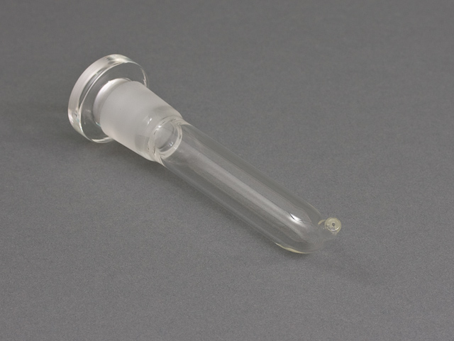
- Semi-indirectly, by first inserting the Luggin tube (RRPG031)
Luggin Tube
through a 24/25 port, followed by insertion of the reference electrode into the inner chamber of the Luggin tube through its 14/20 port. The Luggin tube helps position the tip of the reference probe close to the cylinder insert. Close proximity between the reference and working electrode can reduce the potential shift that arises from uncompensated solution resistance between the reference electrode and the working electrode (RCE cylinder). Use of a Luggin tube becomes unnecessary when the test solution is highly conductive (i.e., having a high salt concentration) and the uncompensated resistance is low enough not to cause a significant measurement error in corrosion potential.
- Indirectly, by a salt bridge (part number AKTUBE1420;
 Reference Electrode Salt Bridge Kit
see next section for details on the salt bridge kit). One can use a salt bridge to physically and diffusionally isolate the reference electrode from the bulk solution. The salt bridge offers a conductive connection between the electrochemical cell (bulk solution) and a separate beaker of the same solution. A salt bridge may be an ideal accessory to use if a reference electrode becomes unstable. Reference electrode instability is often caused by a high solution temperature or by a chemical or physical process that plugs the frit at the tip of the reference electrode.
Reference Electrode Salt Bridge Kit
see next section for details on the salt bridge kit). One can use a salt bridge to physically and diffusionally isolate the reference electrode from the bulk solution. The salt bridge offers a conductive connection between the electrochemical cell (bulk solution) and a separate beaker of the same solution. A salt bridge may be an ideal accessory to use if a reference electrode becomes unstable. Reference electrode instability is often caused by a high solution temperature or by a chemical or physical process that plugs the frit at the tip of the reference electrode.
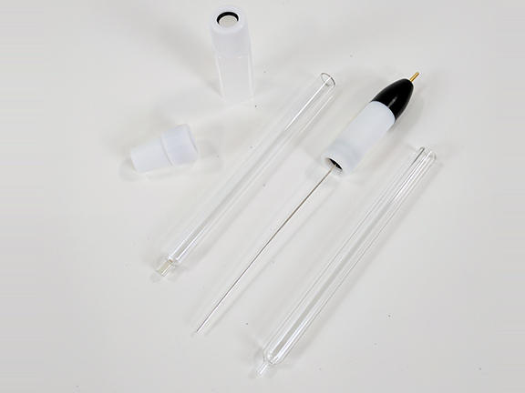
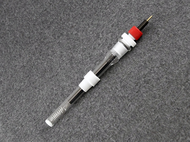
4.6.2Reference Electrode Salt Bridge Kit (AKTUBE1420)
Reference Electrode Salt Bridge Kit
that users may wish to keep in the laboratory (see Figure 17).Figure 17. Reference Electrode Salt Bridge Kit (part number AKTUBE1420)
4.6.3Condenser with 24/25 Joint (RRPG035)
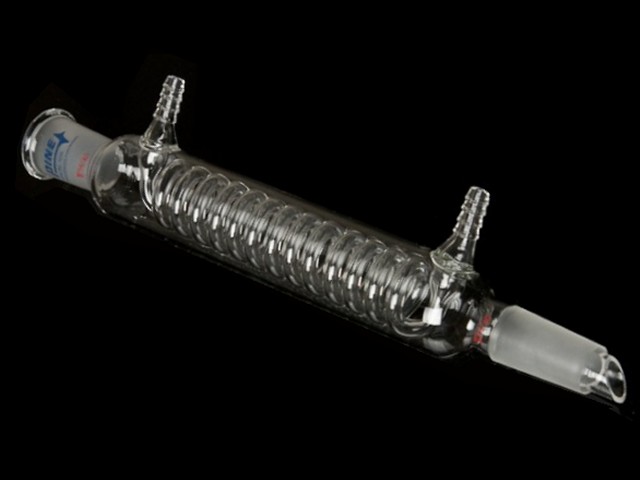 Glass Condenser (24/25 joint)
is an optional corrosion accessory useful for those who perform high temperature experiments (up to 80°C) where appreciable amounts of solvent may evaporate over the duration of a test. The condenser has an inner, spiral-shaped, high surface area tubing path for a cooling water stream that helps cool and condense hot solvent vapors as they rise from the solution, preventing large losses in the electrolyte volume over time (see Figure 18).
Glass Condenser (24/25 joint)
is an optional corrosion accessory useful for those who perform high temperature experiments (up to 80°C) where appreciable amounts of solvent may evaporate over the duration of a test. The condenser has an inner, spiral-shaped, high surface area tubing path for a cooling water stream that helps cool and condense hot solvent vapors as they rise from the solution, preventing large losses in the electrolyte volume over time (see Figure 18).Figure 18. Corrosion Cell Condenser (part number RRPG035)
4.6.4Digital pH Probe with 24/25 PTFE Adapter (AKPH1)
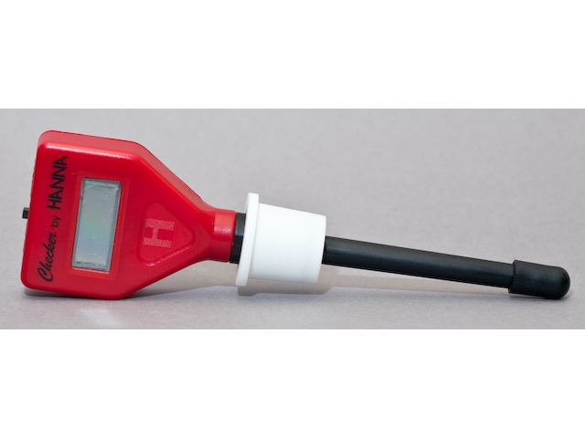 Compact pH Meter
(see Figure 19).
Compact pH Meter
(see Figure 19).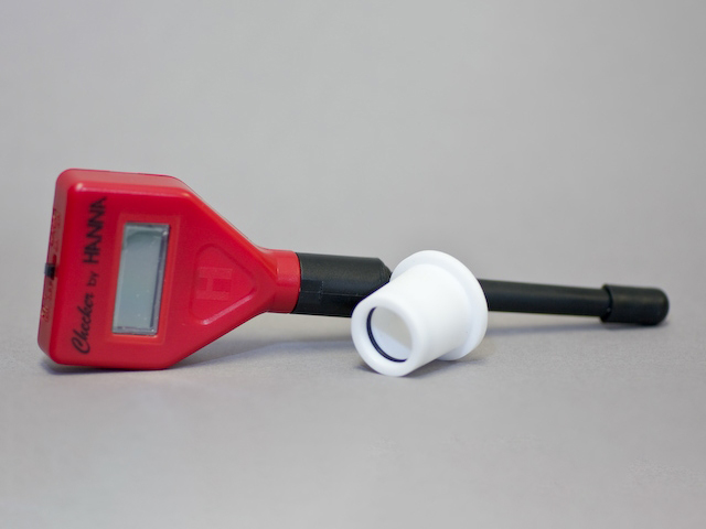
Figure 19. Digital pH Probe with 24/25 PTFE Adapter (part number AKPH1)
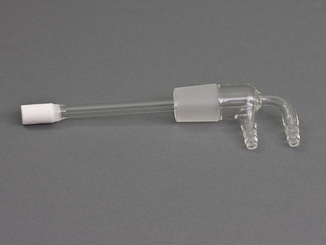
4.6.5Platinum Counter Electrode Assembly (AFCTR5)
 Standard Platinum Counter Electrode
(see Figure 20) over a graphite counter electrode (part number AFCTR3).
Large Graphite Counter Electrode Assembly
In general, highly corrosive conditions over long periods of time may degrade platinum. The platinum counter electrode assembly comes with an isolation tube and PTFE adapter that only fits a 14/20 port, so the 14/20 MutaPort adapter must be used in the OpenTop cell lid.
Standard Platinum Counter Electrode
(see Figure 20) over a graphite counter electrode (part number AFCTR3).
Large Graphite Counter Electrode Assembly
In general, highly corrosive conditions over long periods of time may degrade platinum. The platinum counter electrode assembly comes with an isolation tube and PTFE adapter that only fits a 14/20 port, so the 14/20 MutaPort adapter must be used in the OpenTop cell lid.Figure 20. Standard Platinum Counter Electrode Assembly with Fritted Isolation Tube (part number AFCTR5)
4.6.6Purge Kit for 1/4 Inch Tubing (AKPURGE1)
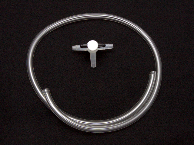 Purge Kit for 1/4" Tubing
is useful to link a gas source (e.g., N2 or Ar) to the dual port purge/sparge accessory (part number RRPG034)
Dual Port Gas Inlet, 24/25
included in the 15 mm RCE product bundles (see Figure 21). The three way valve is useful in regulating flow through solution (bubbling, purging) or blanketing the headspace.
Purge Kit for 1/4" Tubing
is useful to link a gas source (e.g., N2 or Ar) to the dual port purge/sparge accessory (part number RRPG034)
Dual Port Gas Inlet, 24/25
included in the 15 mm RCE product bundles (see Figure 21). The three way valve is useful in regulating flow through solution (bubbling, purging) or blanketing the headspace.Figure 21. Purge Kit for 1/4 Inch Tubing, Including Three-Way Valve (part number AKPURGE1)
4.7Thermal Control Optional Accessories
4.7.1Manual Digital Thermometer with Glass Thermowell (AKTHERM1)
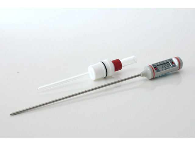 Digital Thermometer in Thermowell
(see Figure 22).
Digital Thermometer in Thermowell
(see Figure 22).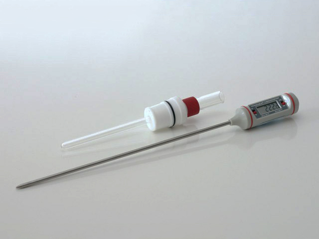
Figure 22. Manual Digital Thermometer with Glass Thermowell and 24/25 PTFE Adapter (part number AKTHERM1)
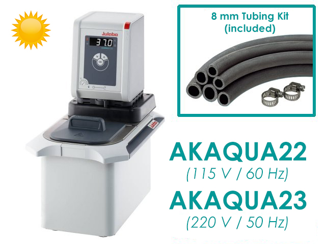
4.7.2Water Circulator Kits
Water Circulator Kits
for further information). The fluid is circulated from the reservoir, out through hoses to the water jacket on the electrochemical cell, and then back to the reservoir. The temperature is typically monitored by a sensor located in the reservoir.
Water Circulator Kits
- Heating only; temperature range +20°C to +100°C
- Part number AKAQUA22 (115 VAC, 60 Hz)
- Part number AKAQUA23 (230 VAC, 50 Hz)
- Heating and cooling; temperature range -20°C to +100°C
- Part number AKAQUA32 (115 VAC, 60 Hz)
- Part number AKAQUA33 (230 VAC, 50 Hz)
- Heating only; with RTD sensor; temperature range +20°C to +200°C
- Part number AKAQUA42 (110-115 VAC, 50-60 Hz)
- Part number AKAQUA43 (230 VAC, 50-60 Hz)
- Heating and cooling; with RTD sensor; temperature range -20°C to +200°C
- Part number AKAQUA52 (115 VAC, 60 Hz)
- Part number AKAQUA53 (220 VAC, 50-60 Hz)
Figure 23. Water Circulator Kits, Heating Only (part numbers AKAQUA22/AKAQUA23)
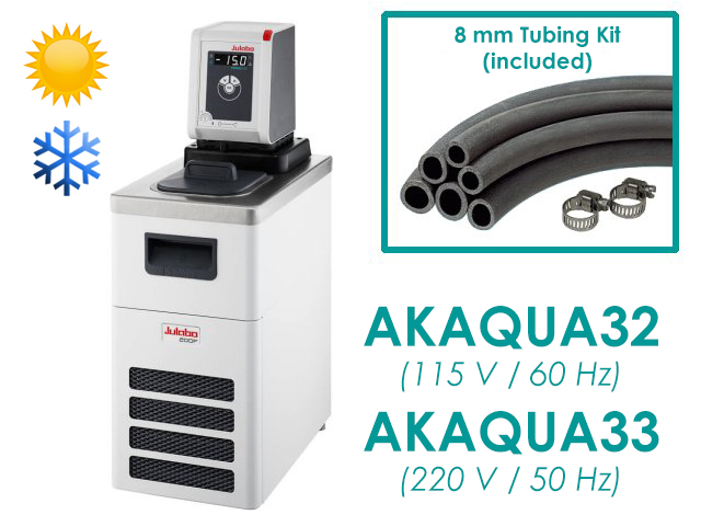
Figure 24. Water Circulator Kits, Heating and Cooling (part numbers AKAQUA32/AKAQUA33)
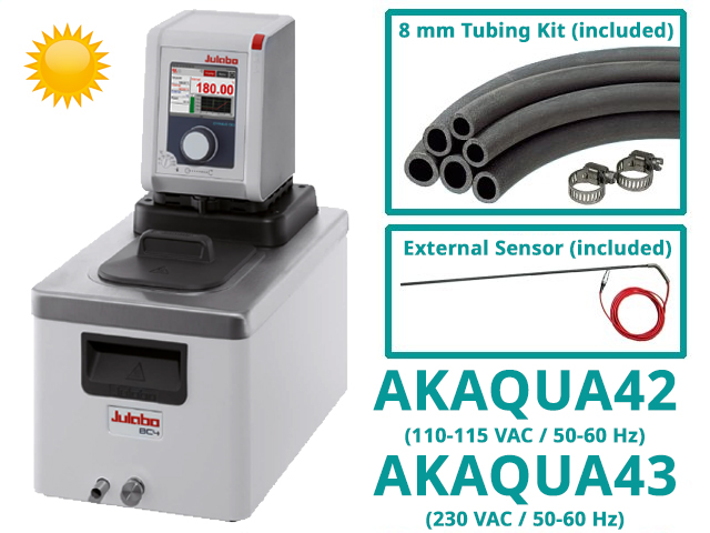
Figure 25. Water Circulator Kits, Heating Only, with RTD Sensor (part numbers AKAQUA42/AKAQUA43)
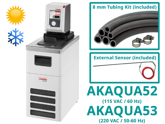
Figure 26. Water Circulator Kits, Heating and Cooling, with RTD Sensor (part numbers AKAQUA52/AKAQUA53)
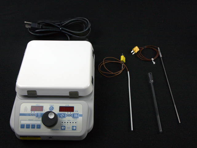
4.7.3Hotplate Kit with Thermocouple Feedback (AKHEATER1/AKHEATER2)
Hotplate Kits
The hotplate kit includes two 8” temperature probe thermocouples, a glass thermowell, and a 7 mm to 24/25 PTFE adapter (see Figure 27). Be sure to select the product whose electrical configuration is matched to the voltage source in your country. The hotplates have a ceramic top and maximum surface temperature of +300°C. It is recommended to use the included thermowell and add either water or high boiling point oil in order to achieve good thermal contact.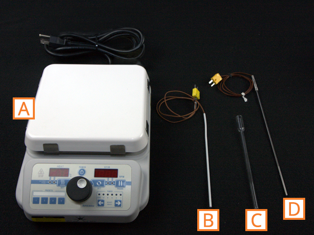 |
|
| Code | Description |
| A | Digital Hotplate (in either 110 VAC or 220 VAC configurations)
Hotplate Kits
|
| B | PTFE-Coated Thermocouple Probe for Temperature Feedback (temperature limit is +190°C) |
| C | Glass Thermowell for Thermocouple Probe |
| D | Stainless Steel Thermocouple Probe for Temperature Feedback (temperature limit is +380°C) |
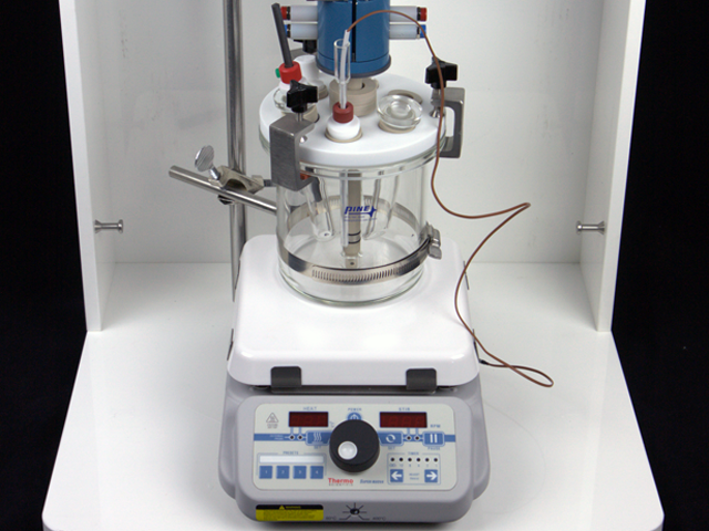
Figure 28. Use of Hotplate and Thermocouple Feedback with AFCELL8U2 under MSR Rotator
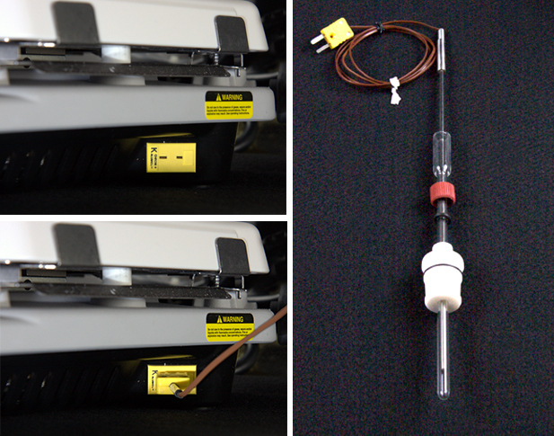
Figure 29. Connected Thermocouple to back of Hotplate