


Study of Mass Transport Limited Corrosion With Rotating Cylinder Electrodes
Last Updated: 1/9/23 by Alex Peroff
Download as PDF1Abstract
This technical note addresses two aspects of electrochemical testing using the Rotating Cylinder Electrode (RCE). First, the fundamental hydrodynamic behavior at a rotating cylinder is summarized, including equations that predict the mass transport limited corrosion current at an RCE. Second, a means of selecting the suitable rotation rate for an RCE test is discussed, with emphasis being placed on matching a particular rotation rate to a particular flow velocity in a smooth pipe. In addition, a bibliography of significant reports regarding the RCE is provided.
2Introduction
Corrosion processes can accelerate significantly under extreme environmental conditions such as high temperature, high pressure, and turbulent fluid flow. When troubleshooting a field corrosion problem, a researcher often needs to return to the lab and reproduce the same (or similar) harsh conditions in a controlled setting. While familiar laboratory equipment for temperature control (ovens, water baths) and pressure control (autoclaves) is generally readily available and easy to use, recreating a fluid flow condition generally poses a larger challenge to the researcher. Laboratory flow loop systems often require complex and expensive plumbing, maintenance, and calibration to reliably and reproducibly move fluid past a metal sample. The need for this type of large scale laboratory equipment can often be avoided by moving the metal sample with respect to the fluid instead.
A convenient instrument for rapidly moving a metal sample with respect to a fluid is the Rotating Cylinder Electrode (RCE).
 Eisenberg, M.; Tobias, C. W.; Wilke, C. R. Ionic Mass Transfer and Concentration Polarization at Rotating Electrodes. Journal of The Electrochemical Society, 1954, 101(6), 306.
Eisenberg, M.; Tobias, C. W.; Wilke, C. R. No title. Chemilca Engineering Progress Symposium Series, 1955, 51, 1.
Gabe, D. R. The rotating cylinder electrode. J. Appl. Electrochem., 1974, 4(2), 91–108.
Gabe, D. R.; Robinson, D. J. Mass transfer in a rotating cylinder cell—I. Laminar flow. Electrochim. Acta, 1972, 17(6), 1121–1127.
Gabe, D. R.; Robinson, D. J. Mass transfer in a rotating cylinder cell—II. Turbulent Flow. Electrochim. Acta, 1972, 17(6), 1129–1137.
Gabe, D. R.; Walsh, F. C. The rotating cylinder electrode: a review of development. J. Appl. Electrochem., 1983, 13(1), 3–21.
Gabe, D. R.; Walsh, F. C. Enhanced mass transfer at the rotating cylinder electrode. I. Characterization of a smooth cylinder and roughness development in solutions of constant concentration. J. Appl. Electrochem., 1984, 14(5), 555–564.
Gabe, D. R.; Walsh, F. C. Enhanced mass transfer at the rotating cylinder electrode. II. Development of roughness for solutions of decreasing concentration. J. Appl. Electrochem., 1984, 14(5), 565–572.
Gabe, D. R.; Walsh, F. C. Enhanced mass transfer at the rotating cylinder electrode: III. Pilot and production plant experience. J. Appl. Electrochem., 1985, 15(6), 807–824.
Gabe, D. R.; Makanjuola, P. A. Enhanced mass transfer using roughened rotating cylinder electrodes in turbulent flow. J. Appl. Electrochem., 1987, 17(2), 370–384.
Gabe, D. R.; Wilcox, G. D.; Gonzalez-Garcia, J.; Walsh, F. C. The rotating cylinder electrode: its continued development and application. J. Appl. Electrochem., 1998, 28(8), 759–780.
Kear, G.; Barker, B. D.; Stokes, K.; Walsh, F. C. Flow influenced electrochemical corrosion of nickel aluminium bronze – Part II. Anodic polarisation and derivation of the mixed potential. J. Appl. Electrochem., 2004, 34(12), 1241–1248.
Kear, G.; Barker, B. D.; Stokes, K.; Walsh, F. C. Flow influenced electrochemical corrosion of nickel aluminium bronze – Part I. Cathodic polarisation. J. Appl. Electrochem., 2004, 34(12), 1235–1240.
Lu, Q.; Stack, M. M.; Wiseman, C. R. AC impedance spectroscopy as a technique for investigating corrosion of iron in hot flowing Bayer liquors. J. Appl. Electrochem., 2001, 31(12), 1373–1379.
Maciel, J. M.; Agostinho, S. M. L. Use of a rotating cylinder electrode in corrosion studies of a 90/10 Cu-Ni alloy in 0.5 M L-1 H2SO4 media. J. Appl. Electrochem., 2000, 30(8), 981–985.
Meštrović-Markovinović, A.; Matić, D. Mass transfer to a rotating horizontal cylinder electrode with full and partial immersion. J. Appl. Electrochem., 1984, 14(5), 675–678.
Grau, J. M.; Bisang, J. M. Mass transfer studies at rotating cylinder electrodes of expanded metal. J. Appl. Electrochem., 2005, 35(3), 285–291.
Eklund, A.; Simonsson, D. Enhanced mass transfer to a rotating cylinder electrode with axial flow. J. Appl. Electrochem., 1988, 18(5), 710–714.
Labraga, L.; Bourabaa, N.; Berkah, T. Wall shear stress from a rotating cylinder in cross flow using the electrochemical technique. Exp. Fluids, 2002, 33(3), 488–496.
Efird, K. D.; Wright, E. J.; Boros, J. A.; Hailey, T. G. Correlation of steel corrosion in pipe flow with jet impingement and rotating cylinder tests. Corrosion, 1993, 49(12), 992–1003.
Silverman, D. C. Rotating Cylinder Electrode for Velocity Sensitivity Testing. Corrosion, 1984, 40(5), 220–226.
Silverman, D. C.; Zerr, M. E. Application of the Rotating Cylinder Electrode—E-Brite 26-1/Concentrated Sulfuric Acid. Corrosion, 1986, 42(11), 633–640.
Silverman, D. C. Rotating Cylinder Electrode-Geometry Relationships for Prediction of Velocity-Sensitive Corrosion. Corrosion, 1988, 44(1), 42–49.
Silverman, D. C. Corrosion prediction in complex environments using electrochemical impedance spectroscopy. Electrochim. Acta, 1993, 38(14), 2075–2078.
Kalota, D. J.; Silverman, D. C. Behavior of Aspartic Acid as a Corrosion Inhibitor for Steel. Corrosion, 1994, 50(2), 138–145.
Silverman, D. C. Technical Note: On Estimating Conditions for Simulating Velocity-Sensitive Corrosion in the Rotating Cylinder Electrode. Corrosion, 1999, 55(12), 1115–1118.
Silverman, D. C. Technical Note: Simplified Equation for Simulating Velocity-Sensitive Corrosion in the Rotating Cylinder Electrode at Higher Reynolds Numbers. Corrosion, 2003, 59(3), 207–211.
Silverman, D. C. The Rotating Cylinder Electrode for Examining Velocity-Sensitive Corrosion—A Review. Corrosion, 2004, 60(11), 1003–1023.
Silverman, D. C. Technical Note: Conditions for Similarity of Mass-Transfer Coefficients and Fluid Shear Stresses between the Rotating Cylinder Electrode and Pipe. Corrosion, 2005, 61(6), 515–518.
Levich, V. G. Physicochemical hydrodynamics, 1st ed. Prentice-Hall: Englewood Cliffs, NJ, 1962.
Holser, R. A.; Prentice, G.; Pond, R. B.; Guanti, R. Use of Rotating Cylinder Electrodes to Simulate Turbulent Flow Conditions in Corroding Systems. Corrosion, 1990, 46(9), 764–769.
Chen, T. Y.; Moccari, A. A.; Macdonald, D. D. Development of Controlled Hydrodynamic Techniques for Corrosion Testing. Corrosion, 1992, 48(3), 239–255.
Nesic, S.; Solvi, G. T.; Skejerve, S. Comparison of rotating cylinder and loop methods for testing CO2 corrosion inhibitors. Br. Corros. J., 1997, 32(4), 269–276.
ASTM G170-01a Standard Guide for Evaluating and Qualifying Oilfield and Refinery Corrosion Inhibitors in the Laboratory. In ASTM International ATSM International: West Conshohocken, PA, 2012.
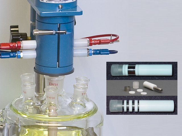
ASTM Editors ASTM G185-06 Standard Practice for Evaluating and Qualifying Oil Field and Refinery Corrosion Inhibitors Using the Rotating Cylinder Electrode ATSM International: West Conshohocken, PA, 2012. This apparatus includes an electrode rotator, RCE electrode shaft, and accessories (see Figure 1) capable of precisely-adjusting the rotation rate of a vertically-oriented shaft.
Eisenberg, M.; Tobias, C. W.; Wilke, C. R. No title. Chemilca Engineering Progress Symposium Series, 1955, 51, 1.
Gabe, D. R. The rotating cylinder electrode. J. Appl. Electrochem., 1974, 4(2), 91–108.
Gabe, D. R.; Robinson, D. J. Mass transfer in a rotating cylinder cell—I. Laminar flow. Electrochim. Acta, 1972, 17(6), 1121–1127.
Gabe, D. R.; Robinson, D. J. Mass transfer in a rotating cylinder cell—II. Turbulent Flow. Electrochim. Acta, 1972, 17(6), 1129–1137.
Gabe, D. R.; Walsh, F. C. The rotating cylinder electrode: a review of development. J. Appl. Electrochem., 1983, 13(1), 3–21.
Gabe, D. R.; Walsh, F. C. Enhanced mass transfer at the rotating cylinder electrode. I. Characterization of a smooth cylinder and roughness development in solutions of constant concentration. J. Appl. Electrochem., 1984, 14(5), 555–564.
Gabe, D. R.; Walsh, F. C. Enhanced mass transfer at the rotating cylinder electrode. II. Development of roughness for solutions of decreasing concentration. J. Appl. Electrochem., 1984, 14(5), 565–572.
Gabe, D. R.; Walsh, F. C. Enhanced mass transfer at the rotating cylinder electrode: III. Pilot and production plant experience. J. Appl. Electrochem., 1985, 15(6), 807–824.
Gabe, D. R.; Makanjuola, P. A. Enhanced mass transfer using roughened rotating cylinder electrodes in turbulent flow. J. Appl. Electrochem., 1987, 17(2), 370–384.
Gabe, D. R.; Wilcox, G. D.; Gonzalez-Garcia, J.; Walsh, F. C. The rotating cylinder electrode: its continued development and application. J. Appl. Electrochem., 1998, 28(8), 759–780.
Kear, G.; Barker, B. D.; Stokes, K.; Walsh, F. C. Flow influenced electrochemical corrosion of nickel aluminium bronze – Part II. Anodic polarisation and derivation of the mixed potential. J. Appl. Electrochem., 2004, 34(12), 1241–1248.
Kear, G.; Barker, B. D.; Stokes, K.; Walsh, F. C. Flow influenced electrochemical corrosion of nickel aluminium bronze – Part I. Cathodic polarisation. J. Appl. Electrochem., 2004, 34(12), 1235–1240.
Lu, Q.; Stack, M. M.; Wiseman, C. R. AC impedance spectroscopy as a technique for investigating corrosion of iron in hot flowing Bayer liquors. J. Appl. Electrochem., 2001, 31(12), 1373–1379.
Maciel, J. M.; Agostinho, S. M. L. Use of a rotating cylinder electrode in corrosion studies of a 90/10 Cu-Ni alloy in 0.5 M L-1 H2SO4 media. J. Appl. Electrochem., 2000, 30(8), 981–985.
Meštrović-Markovinović, A.; Matić, D. Mass transfer to a rotating horizontal cylinder electrode with full and partial immersion. J. Appl. Electrochem., 1984, 14(5), 675–678.
Grau, J. M.; Bisang, J. M. Mass transfer studies at rotating cylinder electrodes of expanded metal. J. Appl. Electrochem., 2005, 35(3), 285–291.
Eklund, A.; Simonsson, D. Enhanced mass transfer to a rotating cylinder electrode with axial flow. J. Appl. Electrochem., 1988, 18(5), 710–714.
Labraga, L.; Bourabaa, N.; Berkah, T. Wall shear stress from a rotating cylinder in cross flow using the electrochemical technique. Exp. Fluids, 2002, 33(3), 488–496.
Efird, K. D.; Wright, E. J.; Boros, J. A.; Hailey, T. G. Correlation of steel corrosion in pipe flow with jet impingement and rotating cylinder tests. Corrosion, 1993, 49(12), 992–1003.
Silverman, D. C. Rotating Cylinder Electrode for Velocity Sensitivity Testing. Corrosion, 1984, 40(5), 220–226.
Silverman, D. C.; Zerr, M. E. Application of the Rotating Cylinder Electrode—E-Brite 26-1/Concentrated Sulfuric Acid. Corrosion, 1986, 42(11), 633–640.
Silverman, D. C. Rotating Cylinder Electrode-Geometry Relationships for Prediction of Velocity-Sensitive Corrosion. Corrosion, 1988, 44(1), 42–49.
Silverman, D. C. Corrosion prediction in complex environments using electrochemical impedance spectroscopy. Electrochim. Acta, 1993, 38(14), 2075–2078.
Kalota, D. J.; Silverman, D. C. Behavior of Aspartic Acid as a Corrosion Inhibitor for Steel. Corrosion, 1994, 50(2), 138–145.
Silverman, D. C. Technical Note: On Estimating Conditions for Simulating Velocity-Sensitive Corrosion in the Rotating Cylinder Electrode. Corrosion, 1999, 55(12), 1115–1118.
Silverman, D. C. Technical Note: Simplified Equation for Simulating Velocity-Sensitive Corrosion in the Rotating Cylinder Electrode at Higher Reynolds Numbers. Corrosion, 2003, 59(3), 207–211.
Silverman, D. C. The Rotating Cylinder Electrode for Examining Velocity-Sensitive Corrosion—A Review. Corrosion, 2004, 60(11), 1003–1023.
Silverman, D. C. Technical Note: Conditions for Similarity of Mass-Transfer Coefficients and Fluid Shear Stresses between the Rotating Cylinder Electrode and Pipe. Corrosion, 2005, 61(6), 515–518.
Levich, V. G. Physicochemical hydrodynamics, 1st ed. Prentice-Hall: Englewood Cliffs, NJ, 1962.
Holser, R. A.; Prentice, G.; Pond, R. B.; Guanti, R. Use of Rotating Cylinder Electrodes to Simulate Turbulent Flow Conditions in Corroding Systems. Corrosion, 1990, 46(9), 764–769.
Chen, T. Y.; Moccari, A. A.; Macdonald, D. D. Development of Controlled Hydrodynamic Techniques for Corrosion Testing. Corrosion, 1992, 48(3), 239–255.
Nesic, S.; Solvi, G. T.; Skejerve, S. Comparison of rotating cylinder and loop methods for testing CO2 corrosion inhibitors. Br. Corros. J., 1997, 32(4), 269–276.
ASTM G170-01a Standard Guide for Evaluating and Qualifying Oilfield and Refinery Corrosion Inhibitors in the Laboratory. In ASTM International ATSM International: West Conshohocken, PA, 2012.
ASTM Editors ASTM G185-06 Standard Practice for Evaluating and Qualifying Oil Field and Refinery Corrosion Inhibitors Using the Rotating Cylinder Electrode ATSM International: West Conshohocken, PA, 2012. This apparatus includes an electrode rotator, RCE electrode shaft, and accessories (see Figure 1) capable of precisely-adjusting the rotation rate of a vertically-oriented shaft.
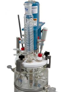
Figure 1. Fully Assembled Pine Research 15 mm OD Rotating Cylinder Electrode System
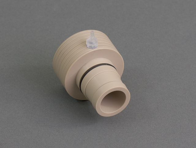
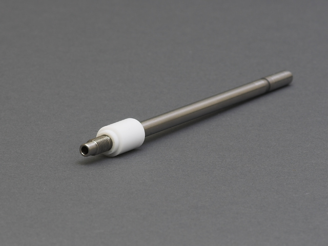
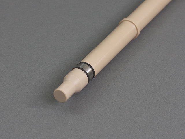
A special tip capable of holding a cylindrical-shaped metal sample is mounted at the lower end of the shaft. The tip is fashioned primarily from chemically-inert and electrically-insulating materials (such as PTFE, PCTFE, or PEEK), but buried within the tip is a metal shank which provides mechanical stability and also electrical contact with the metal cylinder sample, also called a metal coupon (see Figure 2).
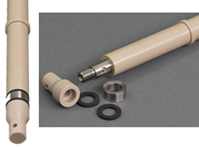
Figure 2. Assembled and Disassembled Views of the 15 mm OD Rotating Cylinder Electrode
When immersed and rotated in a test solution, the hydrodynamic conditions generated by the RCE, even at low rotation rates, are generally quite turbulent.
Eisenberg, M.; Tobias, C. W.; Wilke, C. R. Ionic Mass Transfer and Concentration Polarization at Rotating Electrodes. Journal of The Electrochemical Society, 1954, 101(6), 306.
Eisenberg, M.; Tobias, C. W.; Wilke, C. R. No title. Chemilca Engineering Progress Symposium Series, 1955, 51, 1.
Gabe, D. R. The rotating cylinder electrode. J. Appl. Electrochem., 1974, 4(2), 91–108.
Gabe, D. R.; Robinson, D. J. Mass transfer in a rotating cylinder cell—I. Laminar flow. Electrochim. Acta, 1972, 17(6), 1121–1127.
Gabe, D. R.; Robinson, D. J. Mass transfer in a rotating cylinder cell—II. Turbulent Flow. Electrochim. Acta, 1972, 17(6), 1129–1137. This makes the RCE an ideal probe for studying corrosion processes under turbulent conditions, but at low velocity.
Kear, G.; Barker, B. D.; Stokes, K.; Walsh, F. C. Flow influenced electrochemical corrosion of nickel aluminium bronze – Part II. Anodic polarisation and derivation of the mixed potential. J. Appl. Electrochem., 2004, 34(12), 1241–1248.
Kear, G.; Barker, B. D.; Stokes, K.; Walsh, F. C. Flow influenced electrochemical corrosion of nickel aluminium bronze – Part I. Cathodic polarisation. J. Appl. Electrochem., 2004, 34(12), 1235–1240.
Lu, Q.; Stack, M. M.; Wiseman, C. R. AC impedance spectroscopy as a technique for investigating corrosion of iron in hot flowing Bayer liquors. J. Appl. Electrochem., 2001, 31(12), 1373–1379.
Maciel, J. M.; Agostinho, S. M. L. Use of a rotating cylinder electrode in corrosion studies of a 90/10 Cu-Ni alloy in 0.5 M L-1 H2SO4 media. J. Appl. Electrochem., 2000, 30(8), 981–985. By adjusting the RCE rotation rate up or down (typically in the range from 200 to 4000 RPM), it is possible to tune the hydrodynamic conditions adjacent to the metal sample.
Efird, K. D.; Wright, E. J.; Boros, J. A.; Hailey, T. G. Correlation of steel corrosion in pipe flow with jet impingement and rotating cylinder tests. Corrosion, 1993, 49(12), 992–1003.
Silverman, D. C. Rotating Cylinder Electrode for Velocity Sensitivity Testing. Corrosion, 1984, 40(5), 220–226.
Silverman, D. C.; Zerr, M. E. Application of the Rotating Cylinder Electrode—E-Brite 26-1/Concentrated Sulfuric Acid. Corrosion, 1986, 42(11), 633–640.
Silverman, D. C. Rotating Cylinder Electrode-Geometry Relationships for Prediction of Velocity-Sensitive Corrosion. Corrosion, 1988, 44(1), 42–49.
Silverman, D. C. Corrosion prediction in complex environments using electrochemical impedance spectroscopy. Electrochim. Acta, 1993, 38(14), 2075–2078.
Kalota, D. J.; Silverman, D. C. Behavior of Aspartic Acid as a Corrosion Inhibitor for Steel. Corrosion, 1994, 50(2), 138–145.
Silverman, D. C. Technical Note: On Estimating Conditions for Simulating Velocity-Sensitive Corrosion in the Rotating Cylinder Electrode. Corrosion, 1999, 55(12), 1115–1118.
Silverman, D. C. Technical Note: Simplified Equation for Simulating Velocity-Sensitive Corrosion in the Rotating Cylinder Electrode at Higher Reynolds Numbers. Corrosion, 2003, 59(3), 207–211.
Silverman, D. C. The Rotating Cylinder Electrode for Examining Velocity-Sensitive Corrosion—A Review. Corrosion, 2004, 60(11), 1003–1023.
Silverman, D. C. Technical Note: Conditions for Similarity of Mass-Transfer Coefficients and Fluid Shear Stresses between the Rotating Cylinder Electrode and Pipe. Corrosion, 2005, 61(6), 515–518.
Levich, V. G. Physicochemical hydrodynamics, 1st ed. Prentice-Hall: Englewood Cliffs, NJ, 1962.
Holser, R. A.; Prentice, G.; Pond, R. B.; Guanti, R. Use of Rotating Cylinder Electrodes to Simulate Turbulent Flow Conditions in Corroding Systems. Corrosion, 1990, 46(9), 764–769.
Chen, T. Y.; Moccari, A. A.; Macdonald, D. D. Development of Controlled Hydrodynamic Techniques for Corrosion Testing. Corrosion, 1992, 48(3), 239–255.
Nesic, S.; Solvi, G. T.; Skejerve, S. Comparison of rotating cylinder and loop methods for testing CO2 corrosion inhibitors. Br. Corros. J., 1997, 32(4), 269–276.
ASTM G170-01a Standard Guide for Evaluating and Qualifying Oilfield and Refinery Corrosion Inhibitors in the Laboratory. In ASTM International ATSM International: West Conshohocken, PA, 2012.
ASTM Editors ASTM G185-06 Standard Practice for Evaluating and Qualifying Oil Field and Refinery Corrosion Inhibitors Using the Rotating Cylinder Electrode ATSM International: West Conshohocken, PA, 2012. The ideal goal is to adjust the rotation rate so that the laboratory fluid flow conditions match (or mimic) those found in the field. Once this is accomplished, the corrosion process can be monitored by classic mass loss methods or by electrochemical methods such as Linear Polarization Resistance (LPR)
Silverman, D. C. Rotating Cylinder Electrode for Velocity Sensitivity Testing. Corrosion, 1984, 40(5), 220–226.
Silverman, D. C.; Zerr, M. E. Application of the Rotating Cylinder Electrode—E-Brite 26-1/Concentrated Sulfuric Acid. Corrosion, 1986, 42(11), 633–640. or Electrochemical Impedance Spectroscopy (EIS).
Lu, Q.; Stack, M. M.; Wiseman, C. R. AC impedance spectroscopy as a technique for investigating corrosion of iron in hot flowing Bayer liquors. J. Appl. Electrochem., 2001, 31(12), 1373–1379.
Silverman, D. C. Corrosion prediction in complex environments using electrochemical impedance spectroscopy. Electrochim. Acta, 1993, 38(14), 2075–2078.
Eisenberg, M.; Tobias, C. W.; Wilke, C. R. No title. Chemilca Engineering Progress Symposium Series, 1955, 51, 1.
Gabe, D. R. The rotating cylinder electrode. J. Appl. Electrochem., 1974, 4(2), 91–108.
Gabe, D. R.; Robinson, D. J. Mass transfer in a rotating cylinder cell—I. Laminar flow. Electrochim. Acta, 1972, 17(6), 1121–1127.
Gabe, D. R.; Robinson, D. J. Mass transfer in a rotating cylinder cell—II. Turbulent Flow. Electrochim. Acta, 1972, 17(6), 1129–1137. This makes the RCE an ideal probe for studying corrosion processes under turbulent conditions, but at low velocity.
Kear, G.; Barker, B. D.; Stokes, K.; Walsh, F. C. Flow influenced electrochemical corrosion of nickel aluminium bronze – Part I. Cathodic polarisation. J. Appl. Electrochem., 2004, 34(12), 1235–1240.
Lu, Q.; Stack, M. M.; Wiseman, C. R. AC impedance spectroscopy as a technique for investigating corrosion of iron in hot flowing Bayer liquors. J. Appl. Electrochem., 2001, 31(12), 1373–1379.
Maciel, J. M.; Agostinho, S. M. L. Use of a rotating cylinder electrode in corrosion studies of a 90/10 Cu-Ni alloy in 0.5 M L-1 H2SO4 media. J. Appl. Electrochem., 2000, 30(8), 981–985. By adjusting the RCE rotation rate up or down (typically in the range from 200 to 4000 RPM), it is possible to tune the hydrodynamic conditions adjacent to the metal sample.
Silverman, D. C. Rotating Cylinder Electrode for Velocity Sensitivity Testing. Corrosion, 1984, 40(5), 220–226.
Silverman, D. C.; Zerr, M. E. Application of the Rotating Cylinder Electrode—E-Brite 26-1/Concentrated Sulfuric Acid. Corrosion, 1986, 42(11), 633–640.
Silverman, D. C. Rotating Cylinder Electrode-Geometry Relationships for Prediction of Velocity-Sensitive Corrosion. Corrosion, 1988, 44(1), 42–49.
Silverman, D. C. Corrosion prediction in complex environments using electrochemical impedance spectroscopy. Electrochim. Acta, 1993, 38(14), 2075–2078.
Kalota, D. J.; Silverman, D. C. Behavior of Aspartic Acid as a Corrosion Inhibitor for Steel. Corrosion, 1994, 50(2), 138–145.
Silverman, D. C. Technical Note: On Estimating Conditions for Simulating Velocity-Sensitive Corrosion in the Rotating Cylinder Electrode. Corrosion, 1999, 55(12), 1115–1118.
Silverman, D. C. Technical Note: Simplified Equation for Simulating Velocity-Sensitive Corrosion in the Rotating Cylinder Electrode at Higher Reynolds Numbers. Corrosion, 2003, 59(3), 207–211.
Silverman, D. C. The Rotating Cylinder Electrode for Examining Velocity-Sensitive Corrosion—A Review. Corrosion, 2004, 60(11), 1003–1023.
Silverman, D. C. Technical Note: Conditions for Similarity of Mass-Transfer Coefficients and Fluid Shear Stresses between the Rotating Cylinder Electrode and Pipe. Corrosion, 2005, 61(6), 515–518.
Levich, V. G. Physicochemical hydrodynamics, 1st ed. Prentice-Hall: Englewood Cliffs, NJ, 1962.
Holser, R. A.; Prentice, G.; Pond, R. B.; Guanti, R. Use of Rotating Cylinder Electrodes to Simulate Turbulent Flow Conditions in Corroding Systems. Corrosion, 1990, 46(9), 764–769.
Chen, T. Y.; Moccari, A. A.; Macdonald, D. D. Development of Controlled Hydrodynamic Techniques for Corrosion Testing. Corrosion, 1992, 48(3), 239–255.
Nesic, S.; Solvi, G. T.; Skejerve, S. Comparison of rotating cylinder and loop methods for testing CO2 corrosion inhibitors. Br. Corros. J., 1997, 32(4), 269–276.
ASTM G170-01a Standard Guide for Evaluating and Qualifying Oilfield and Refinery Corrosion Inhibitors in the Laboratory. In ASTM International ATSM International: West Conshohocken, PA, 2012.
ASTM Editors ASTM G185-06 Standard Practice for Evaluating and Qualifying Oil Field and Refinery Corrosion Inhibitors Using the Rotating Cylinder Electrode ATSM International: West Conshohocken, PA, 2012. The ideal goal is to adjust the rotation rate so that the laboratory fluid flow conditions match (or mimic) those found in the field. Once this is accomplished, the corrosion process can be monitored by classic mass loss methods or by electrochemical methods such as Linear Polarization Resistance (LPR)
Silverman, D. C.; Zerr, M. E. Application of the Rotating Cylinder Electrode—E-Brite 26-1/Concentrated Sulfuric Acid. Corrosion, 1986, 42(11), 633–640. or Electrochemical Impedance Spectroscopy (EIS).
Silverman, D. C. Corrosion prediction in complex environments using electrochemical impedance spectroscopy. Electrochim. Acta, 1993, 38(14), 2075–2078.
3Tuning Turbulent Flow
At very slow rotation rates, the solution near a rotating cylinder flows with a regular and smooth motion called laminar flow. As the rotation rate increases, the solution flow becomes more complex. While the layer of solution in direct contact with the cylinder continues to cling to the surface, the shear stress between this layer and layers further from the cylinder begins to spin off vortices. At this point, the solution flow transitions from laminar to turbulent flow, and as the rotation rate increases, the vortices themselves spawn further vortices.
The transition from laminar to turbulent flow is often characterized using the Reynolds Number (RE) to quantify the ratio between inertial forces and viscous forces in a solution. For a rotating cylinder electrode with outer diameter, dcyl (cm), and radius, dcyl/2, the Reynolds Number is shown in Equation 1:
Eisenberg, M.; Tobias, C. W.; Wilke, C. R. Ionic Mass Transfer and Concentration Polarization at Rotating Electrodes. Journal of The Electrochemical Society, 1954, 101(6), 306.
Eisenberg, M.; Tobias, C. W.; Wilke, C. R. No title. Chemilca Engineering Progress Symposium Series, 1955, 51, 1.
Gabe, D. R. The rotating cylinder electrode. J. Appl. Electrochem., 1974, 4(2), 91–108.
Eisenberg, M.; Tobias, C. W.; Wilke, C. R. No title. Chemilca Engineering Progress Symposium Series, 1955, 51, 1.
Gabe, D. R. The rotating cylinder electrode. J. Appl. Electrochem., 1974, 4(2), 91–108.
 |
(1) |
where ρ is the solution density (g/cm3), and μ is the absolute viscosity of the solution (g/cm s). The linear velocity, Ucyl (cm/s), at the outer surface of the cylinder is given by Equation 2:
 |
(2) |
where the rate can either be expressed as angular rotation rate, ω (rad/s), or as frequency, F (RPM). In general, for a rotating cylinder, when the Reynolds Number is greater than 200, then the flow is turbulent.
For all but the very slowest rotation rates, the turbulent condition is expected and desired. So, for a typical Pine Research RCE (15 mm OD, see Figure 2),
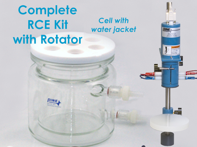 Complete RCE Bundle with Rotator and Jacketed Cell
rotation rates between 5 and 4000 RPM correspond to a range of Reynolds Numbers spanning several orders of magnitude (see Table 1 in Section 9.1). The transition from laminar to turbulent flow occurs just above 20 RPM, when the Reynolds Number exceeds 200. It is worth noting that this transition occurs at a relatively small rotation rate, making the RCE an ideal tool for studying turbulent flow at low velocity—precisely the condition frequently found in pipeline infrastructures. Higher turbulent velocities are also easily accessible at higher rotation rates.
Complete RCE Bundle with Rotator and Jacketed Cell
rotation rates between 5 and 4000 RPM correspond to a range of Reynolds Numbers spanning several orders of magnitude (see Table 1 in Section 9.1). The transition from laminar to turbulent flow occurs just above 20 RPM, when the Reynolds Number exceeds 200. It is worth noting that this transition occurs at a relatively small rotation rate, making the RCE an ideal tool for studying turbulent flow at low velocity—precisely the condition frequently found in pipeline infrastructures. Higher turbulent velocities are also easily accessible at higher rotation rates. 4Mass Transport
The turbulent flow at the RCE can bring material from the solution to the surface of the cylinder, and it can also carry material away from the surface. In the context of a corrosion study, the rate of mass transport to and from the metal surface is often the factor which governs the rate of corrosion. A familiar example would be a corrosion process which is limited by how fast oxygen can be transported from the solution to the metal surface.
Early reports by Eisenberg provide the most commonly accepted description for RCE mass transport.
Eisenberg, M.; Tobias, C. W.; Wilke, C. R. Ionic Mass Transfer and Concentration Polarization at Rotating Electrodes. Journal of The Electrochemical Society, 1954, 101(6), 306.
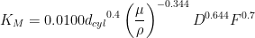
Eisenberg, M.; Tobias, C. W.; Wilke, C. R. No title. Chemilca Engineering Progress Symposium Series, 1955, 51, 1. In particular, the mass transfer coefficient, KM (cm/s), to a rotating cylinder is given by the following relationship:
Eisenberg, M.; Tobias, C. W.; Wilke, C. R. No title. Chemilca Engineering Progress Symposium Series, 1955, 51, 1. In particular, the mass transfer coefficient, KM (cm/s), to a rotating cylinder is given by the following relationship:
![\displaystyle{K_M = S_H \frac{D}{d_{cyl}} = [0.0791 {R_E}^{0.7} {Sc}^{0.356}]\left(\frac{D}{d_{cyl}}\right) }](https://s0.wp.com/latex.php?latex=%5Cdisplaystyle%7BK_M+%3D+S_H+%5Cfrac%7BD%7D%7Bd_%7Bcyl%7D%7D%C2%A0+%3D+%5B0.0791+%7BR_E%7D%5E%7B0.7%7D+%7BSc%7D%5E%7B0.356%7D%5D%5Cleft%28%5Cfrac%7BD%7D%7Bd_%7Bcyl%7D%7D%5Cright%29+%7D&bg=ffffff&fg=000&s=0&c=20201002) |
(3) |
where the diffusion coefficient, D (cm2/s), is usually taken as the diffusion coefficient for the molecule or ion undergoing mass transport, and where SH and RE are the dimensionless Sherwood and Reynolds Numbers, respectively. The Schmidt Number, SC = μ/ρD, is also a dimensionless number.
Combining Equations 1 - 3, the overall mass transfer coefficient to an RCE can be expressed in one of three forms, as shown in Equations 4a - 4c:
 |
(4a) |
 |
(4b) |
 |
(4c) |
The exact form depends upon whether the rotation rate is expressed in terms of linear surface velocity (Ucyl), angular rotation rate (ω), or rotations per minute (F). Note that the form shown in Equation 4a is that which is most often found in the literature.
5Wall Shear Stress
The turbulent flow at the RCE induces a wall shear stress on the surface of the cylinder. Again, Eisenberg’s original reports offer a well accepted equation for the wall stress, τcyl (g/cm s):
Eisenberg, M.; Tobias, C. W.; Wilke, C. R. Ionic Mass Transfer and Concentration Polarization at Rotating Electrodes. Journal of The Electrochemical Society, 1954, 101(6), 306.
Eisenberg, M.; Tobias, C. W.; Wilke, C. R. No title. Chemilca Engineering Progress Symposium Series, 1955, 51, 1.
ASTM Editors ASTM G185-06 Standard Practice for Evaluating and Qualifying Oil Field and Refinery Corrosion Inhibitors Using the Rotating Cylinder Electrode ATSM International: West Conshohocken, PA, 2012.
 |
(5) |
The wall shear stress for a typical Pine Research RCE tip (dcyl = 1.5 cm) over a range of rotation rates is listed in Table 1 in Section 9.1.
6Electrochemical Measurements
When a rotating cylinder is used as the working electrode in a traditional three-electrode cell configuration, the corrosion behavior can be monitored by measuring the electric current at the cylinder.
ASTM G170-01a Standard Guide for Evaluating and Qualifying Oilfield and Refinery Corrosion Inhibitors in the Laboratory. In ASTM International ATSM International: West Conshohocken, PA, 2012.
ASTM Editors ASTM G185-06 Standard Practice for Evaluating and Qualifying Oil Field and Refinery Corrosion Inhibitors Using the Rotating Cylinder Electrode ATSM International: West Conshohocken, PA, 2012. Electrical connection to the metal cylinder is accomplished by means of a brush contact on the rotating shaft. A potentiostat is employed to impose various potentials on the cylinder electrode while simultaneously measuring the current. The potential signal applied to the cylinder may be a very slow voltage sweep (e.g., Linear Polarization Resistance, LPR),
Silverman, D. C. Rotating Cylinder Electrode for Velocity Sensitivity Testing. Corrosion, 1984, 40(5), 220–226.
Silverman, D. C.; Zerr, M. E. Application of the Rotating Cylinder Electrode—E-Brite 26-1/Concentrated Sulfuric Acid. Corrosion, 1986, 42(11), 633–640. or it may involve a high frequency sinusoidal signal (i.e., Electrochemical Impedance Spectroscopy, EIS).
Lu, Q.; Stack, M. M.; Wiseman, C. R. AC impedance spectroscopy as a technique for investigating corrosion of iron in hot flowing Bayer liquors. J. Appl. Electrochem., 2001, 31(12), 1373–1379.
Silverman, D. C. Corrosion prediction in complex environments using electrochemical impedance spectroscopy. Electrochim. Acta, 1993, 38(14), 2075–2078.
ASTM Editors ASTM G185-06 Standard Practice for Evaluating and Qualifying Oil Field and Refinery Corrosion Inhibitors Using the Rotating Cylinder Electrode ATSM International: West Conshohocken, PA, 2012. Electrical connection to the metal cylinder is accomplished by means of a brush contact on the rotating shaft. A potentiostat is employed to impose various potentials on the cylinder electrode while simultaneously measuring the current. The potential signal applied to the cylinder may be a very slow voltage sweep (e.g., Linear Polarization Resistance, LPR),
Silverman, D. C.; Zerr, M. E. Application of the Rotating Cylinder Electrode—E-Brite 26-1/Concentrated Sulfuric Acid. Corrosion, 1986, 42(11), 633–640. or it may involve a high frequency sinusoidal signal (i.e., Electrochemical Impedance Spectroscopy, EIS).
Silverman, D. C. Corrosion prediction in complex environments using electrochemical impedance spectroscopy. Electrochim. Acta, 1993, 38(14), 2075–2078.
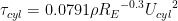
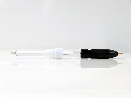
Two other electrodes are also required to make an electrochemical measurement, a reference electrode (such as a silver/silver-chloride electrode)
 Single Junction Silver Chloride Reference Electrode
and a counter electrode.
Single Junction Silver Chloride Reference Electrode
and a counter electrode.
 Large Graphite Counter Electrode Assembly
The counter electrode is often an even larger diameter cylinder, rod, wire loop, or flag placed in the solution so that it surrounds the rotating cylinder. This helps to assure uniform current density at the RCE during the test.
Large Graphite Counter Electrode Assembly
The counter electrode is often an even larger diameter cylinder, rod, wire loop, or flag placed in the solution so that it surrounds the rotating cylinder. This helps to assure uniform current density at the RCE during the test.
Single Junction Silver Chloride Reference Electrode
and a counter electrode.
Large Graphite Counter Electrode Assembly
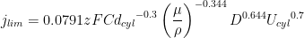
The counter electrode is often an even larger diameter cylinder, rod, wire loop, or flag placed in the solution so that it surrounds the rotating cylinder. This helps to assure uniform current density at the RCE during the test.In general, the mass transport limited current density, jlim (A/cm2), observed in an electrochemical experiment is related to the mass transfer coefficient by the following relationship:
 |
(6) |
where F is Faraday’s constant (96485 C/mol), ilim (A) is the limiting current, and A (cm2) is the area of the electrode. To make full quantitative use of this relationship, both the number of electrons exchanged, z, and the bulk concentration of the ion or molecule involved in the electrochemical process, C (mol/cm3), must be known.
Combining equations (4) and (6), the mass transport-limited current density can be expressed as follows:
 |
(7a) |
 |
(7b) |
Thus, if a corrosion process is limited by mass transport, it is expected that the limiting current (or limiting current density) will vary linearly with the rotation rate raised to the 0.7 power (ω0.7). Note that this behavior can be verified even without explicit knowledge of z and C simply by conducting a set of measurements at several different rotation rates.
Silverman, D. C. The Rotating Cylinder Electrode for Examining Velocity-Sensitive Corrosion—A Review. Corrosion, 2004, 60(11), 1003–1023.
For example, consider a series of LPR scans performed over a range of rotation rates (see Figure 3). As the rotation rate increases, so does the observed current. A log/log plot of the limiting current (or limiting current density) versus the rotation rate will reveal whether or not the observed current is mass transport-limited (see Figure 4). If the slope of a line drawn through the points on this plot is near 0.7, then this is good evidence that the corrosion process is limited by mass transport.
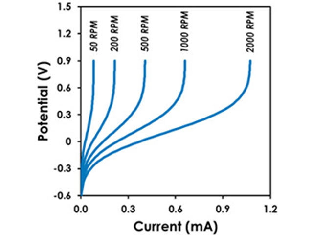
Figure 3. Example of a Series of LPR Scans Recorded at Various Rotation Rates
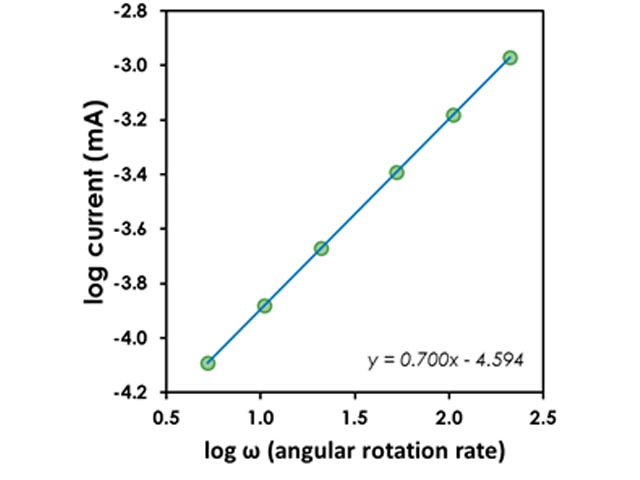
Figure 4. Logarithmic Plot to Test for Mass Transport-Limited Corrosion Process
7Modeling Pipeline Flow
A critical issue when attempting to use the RCE to match or mimic a field corrosion condition is choosing the proper rotation rate at which to perform electrochemical measurements. Several solutions to this problem have been proposed over the years.
Efird, K. D.; Wright, E. J.; Boros, J. A.; Hailey, T. G. Correlation of steel corrosion in pipe flow with jet impingement and rotating cylinder tests. Corrosion, 1993, 49(12), 992–1003.
Silverman, D. C. Rotating Cylinder Electrode for Velocity Sensitivity Testing. Corrosion, 1984, 40(5), 220–226.
Silverman, D. C.; Zerr, M. E. Application of the Rotating Cylinder Electrode—E-Brite 26-1/Concentrated Sulfuric Acid. Corrosion, 1986, 42(11), 633–640.
Silverman, D. C. Rotating Cylinder Electrode-Geometry Relationships for Prediction of Velocity-Sensitive Corrosion. Corrosion, 1988, 44(1), 42–49.
Silverman, D. C. Corrosion prediction in complex environments using electrochemical impedance spectroscopy. Electrochim. Acta, 1993, 38(14), 2075–2078.
Kalota, D. J.; Silverman, D. C. Behavior of Aspartic Acid as a Corrosion Inhibitor for Steel. Corrosion, 1994, 50(2), 138–145.
Silverman, D. C. Technical Note: On Estimating Conditions for Simulating Velocity-Sensitive Corrosion in the Rotating Cylinder Electrode. Corrosion, 1999, 55(12), 1115–1118.
Silverman, D. C. Technical Note: Simplified Equation for Simulating Velocity-Sensitive Corrosion in the Rotating Cylinder Electrode at Higher Reynolds Numbers. Corrosion, 2003, 59(3), 207–211.
Silverman, D. C. The Rotating Cylinder Electrode for Examining Velocity-Sensitive Corrosion—A Review. Corrosion, 2004, 60(11), 1003–1023.
Silverman, D. C. Technical Note: Conditions for Similarity of Mass-Transfer Coefficients and Fluid Shear Stresses between the Rotating Cylinder Electrode and Pipe. Corrosion, 2005, 61(6), 515–518.
Levich, V. G. Physicochemical hydrodynamics, 1st ed. Prentice-Hall: Englewood Cliffs, NJ, 1962.
Holser, R. A.; Prentice, G.; Pond, R. B.; Guanti, R. Use of Rotating Cylinder Electrodes to Simulate Turbulent Flow Conditions in Corroding Systems. Corrosion, 1990, 46(9), 764–769.
Chen, T. Y.; Moccari, A. A.; Macdonald, D. D. Development of Controlled Hydrodynamic Techniques for Corrosion Testing. Corrosion, 1992, 48(3), 239–255.
Nesic, S.; Solvi, G. T.; Skejerve, S. Comparison of rotating cylinder and loop methods for testing CO2 corrosion inhibitors. Br. Corros. J., 1997, 32(4), 269–276.
ASTM G170-01a Standard Guide for Evaluating and Qualifying Oilfield and Refinery Corrosion Inhibitors in the Laboratory. In ASTM International ATSM International: West Conshohocken, PA, 2012.
ASTM Editors ASTM G185-06 Standard Practice for Evaluating and Qualifying Oil Field and Refinery Corrosion Inhibitors Using the Rotating Cylinder Electrode ATSM International: West Conshohocken, PA, 2012. Most involve operating the RCE at a rotation rate where the wall shear stress matches that found in the field, or alternately, at a rate where the mass transport coefficient at the RCE matches that observed in the field.
The discussion here will be limited to the latter case, but at the outset, it is important to note that modeling a field corrosion situation in the laboratory involves some compromise and some assumptions. When an RCE is operated at a rotation rate that produces similar mass transport conditions to those found in the field, it is assumed that the corrosion mechanism occurring in the field will be reproduced in the laboratory.
Silverman, D. C. The Rotating Cylinder Electrode for Examining Velocity-Sensitive Corrosion—A Review. Corrosion, 2004, 60(11), 1003–1023.
However, it is not expected that the actual corrosion rate at the RCE will match that found in the field. There have been specific cases where the RCE failed to reproduce the field corrosion condition.
Efird, K. D.; Wright, E. J.; Boros, J. A.; Hailey, T. G. Correlation of steel corrosion in pipe flow with jet impingement and rotating cylinder tests. Corrosion, 1993, 49(12), 992–1003.
Particular attention is required when surface roughness influences mass transport.
Gabe, D. R.; Walsh, F. C. Enhanced mass transfer at the rotating cylinder electrode. I. Characterization of a smooth cylinder and roughness development in solutions of constant concentration. J. Appl. Electrochem., 1984, 14(5), 555–564.
Gabe, D. R.; Walsh, F. C. Enhanced mass transfer at the rotating cylinder electrode. II. Development of roughness for solutions of decreasing concentration. J. Appl. Electrochem., 1984, 14(5), 565–572.
Gabe, D. R.; Walsh, F. C. Enhanced mass transfer at the rotating cylinder electrode: III. Pilot and production plant experience. J. Appl. Electrochem., 1985, 15(6), 807–824.
Gabe, D. R.; Makanjuola, P. A. Enhanced mass transfer using roughened rotating cylinder electrodes in turbulent flow. J. Appl. Electrochem., 1987, 17(2), 370–384.
Silverman, D. C. The Rotating Cylinder Electrode for Examining Velocity-Sensitive Corrosion—A Review. Corrosion, 2004, 60(11), 1003–1023. And lastly, there are practical limitations on the range of pipe diameters accessible with the RCE method.
Silverman, D. C. Technical Note: Conditions for Similarity of Mass-Transfer Coefficients and Fluid Shear Stresses between the Rotating Cylinder Electrode and Pipe. Corrosion, 2005, 61(6), 515–518.
Gabe, D. R.; Walsh, F. C. Enhanced mass transfer at the rotating cylinder electrode. II. Development of roughness for solutions of decreasing concentration. J. Appl. Electrochem., 1984, 14(5), 565–572.
Gabe, D. R.; Walsh, F. C. Enhanced mass transfer at the rotating cylinder electrode: III. Pilot and production plant experience. J. Appl. Electrochem., 1985, 15(6), 807–824.
Gabe, D. R.; Makanjuola, P. A. Enhanced mass transfer using roughened rotating cylinder electrodes in turbulent flow. J. Appl. Electrochem., 1987, 17(2), 370–384.
Silverman, D. C. The Rotating Cylinder Electrode for Examining Velocity-Sensitive Corrosion—A Review. Corrosion, 2004, 60(11), 1003–1023. And lastly, there are practical limitations on the range of pipe diameters accessible with the RCE method.
With these caveats in mind, a computational approach outlined in several reports by Silverman
Silverman, D. C. Rotating Cylinder Electrode for Velocity Sensitivity Testing. Corrosion, 1984, 40(5), 220–226.
Silverman, D. C.; Zerr, M. E. Application of the Rotating Cylinder Electrode—E-Brite 26-1/Concentrated Sulfuric Acid. Corrosion, 1986, 42(11), 633–640.
Silverman, D. C. Rotating Cylinder Electrode-Geometry Relationships for Prediction of Velocity-Sensitive Corrosion. Corrosion, 1988, 44(1), 42–49.
Silverman, D. C. Corrosion prediction in complex environments using electrochemical impedance spectroscopy. Electrochim. Acta, 1993, 38(14), 2075–2078.
Kalota, D. J.; Silverman, D. C. Behavior of Aspartic Acid as a Corrosion Inhibitor for Steel. Corrosion, 1994, 50(2), 138–145.
Silverman, D. C. Technical Note: On Estimating Conditions for Simulating Velocity-Sensitive Corrosion in the Rotating Cylinder Electrode. Corrosion, 1999, 55(12), 1115–1118.
Silverman, D. C. Technical Note: Simplified Equation for Simulating Velocity-Sensitive Corrosion in the Rotating Cylinder Electrode at Higher Reynolds Numbers. Corrosion, 2003, 59(3), 207–211.
Silverman, D. C. The Rotating Cylinder Electrode for Examining Velocity-Sensitive Corrosion—A Review. Corrosion, 2004, 60(11), 1003–1023.
Silverman, D. C. Technical Note: Conditions for Similarity of Mass-Transfer Coefficients and Fluid Shear Stresses between the Rotating Cylinder Electrode and Pipe. Corrosion, 2005, 61(6), 515–518. (who, in turn, references reports by Wranglen,
Levich, V. G. Physicochemical hydrodynamics, 1st ed. Prentice-Hall: Englewood Cliffs, NJ, 1962.
Holser,
Holser, R. A.; Prentice, G.; Pond, R. B.; Guanti, R. Use of Rotating Cylinder Electrodes to Simulate Turbulent Flow Conditions in Corroding Systems. Corrosion, 1990, 46(9), 764–769.
Chen,
Chen, T. Y.; Moccari, A. A.; Macdonald, D. D. Development of Controlled Hydrodynamic Techniques for Corrosion Testing. Corrosion, 1992, 48(3), 239–255.
and Nesic
Nesic, S.; Solvi, G. T.; Skejerve, S. Comparison of rotating cylinder and loop methods for testing CO2 corrosion inhibitors. Br. Corros. J., 1997, 32(4), 269–276.
) is summarized here. Consider turbulent flow through a smooth, straight pipe. If the flow rate through the pipe, Up (cm/s), is known, then the target surface velocity, Ucyl (cm/s), at an RCE that produces a nearly equivalent mass transport condition can be estimated as follows:
Silverman, D. C. The Rotating Cylinder Electrode for Examining Velocity-Sensitive Corrosion—A Review. Corrosion, 2004, 60(11), 1003–1023.
Silverman, D. C.; Zerr, M. E. Application of the Rotating Cylinder Electrode—E-Brite 26-1/Concentrated Sulfuric Acid. Corrosion, 1986, 42(11), 633–640.
Silverman, D. C. Rotating Cylinder Electrode-Geometry Relationships for Prediction of Velocity-Sensitive Corrosion. Corrosion, 1988, 44(1), 42–49.
Silverman, D. C. Corrosion prediction in complex environments using electrochemical impedance spectroscopy. Electrochim. Acta, 1993, 38(14), 2075–2078.
Kalota, D. J.; Silverman, D. C. Behavior of Aspartic Acid as a Corrosion Inhibitor for Steel. Corrosion, 1994, 50(2), 138–145.
Silverman, D. C. Technical Note: On Estimating Conditions for Simulating Velocity-Sensitive Corrosion in the Rotating Cylinder Electrode. Corrosion, 1999, 55(12), 1115–1118.
Silverman, D. C. Technical Note: Simplified Equation for Simulating Velocity-Sensitive Corrosion in the Rotating Cylinder Electrode at Higher Reynolds Numbers. Corrosion, 2003, 59(3), 207–211.
Silverman, D. C. The Rotating Cylinder Electrode for Examining Velocity-Sensitive Corrosion—A Review. Corrosion, 2004, 60(11), 1003–1023.
Silverman, D. C. Technical Note: Conditions for Similarity of Mass-Transfer Coefficients and Fluid Shear Stresses between the Rotating Cylinder Electrode and Pipe. Corrosion, 2005, 61(6), 515–518. (who, in turn, references reports by Wranglen,
 |
(8) |
where dp (cm) is the diameter of the pipe. Using this relationship together with Equation 2, it is possible to compute a target rotation rate for the RCE.
Equation 8 has too many parameters to plot convenient working curves on a graph. To convey some idea of the type of results produced using this equation, Table 2 in Section 9.1 lists the pipe velocity/rotation rate relationships for a typical Pine Research RCE (dcyl = 1.5 cm and A = 3.0 cm2) operating in pure water. As an example, if water is flowing through a smooth 10 in Schedule 40 pipe at 1.0 ft/s, an RCE should be operated at about 131 RPM to match the conditions in the pipe.
Pine Research has created a spreadsheet calculator to aid in RCE calculations that can be downloaded at this link.
8Corrosion Instrumentation
Pine Research offers specialized tools for the study of mass transport-limited corrosion. In addition to our potentiostats for measuring corrosion current and potential, we design and manufacture complete corrosion cell kits. These laboratory corrosion cells have been designed based on input we have received from researchers and practitioners in the corrosion community. The corrosion cell is designed to be sturdy, long-lasting, and easily integrated with other Pine Research products.
The Pine Research classic RCE system was based on a 12 mm OD RCE (see Table 3 in Section 9.2),
 Classic 12 mm RCE Bundle with Rotator
but an improved system based on a 15 mm OD RCE is now available (see Table 1 in Section 9.1).
Complete RCE Bundle with Rotator and Jacketed Cell
The Pine Research 15 mm OD Rotating Cylinder Electrode System has many features listed below. Additionally, Figures 5 and 6 show the components of the 15 mm OD RCE system.
Classic 12 mm RCE Bundle with Rotator
but an improved system based on a 15 mm OD RCE is now available (see Table 1 in Section 9.1).
Complete RCE Bundle with Rotator and Jacketed Cell
The Pine Research 15 mm OD Rotating Cylinder Electrode System has many features listed below. Additionally, Figures 5 and 6 show the components of the 15 mm OD RCE system.- Reliable electrical contact between the shaft and the replaceable cylinder insert is accomplished using a spring-loaded ball plunger that pushes against the inside diameter of the cylinder insert.
- All shaft components are fabricated from a chemically-resistant polymer, polyether ether ketone (PEEK),
 Electrode Shroud Materials Overview
to protect the shaft from corrosive attack during testing. PEEK has good mechanical stability at elevated temperatures (up to 80°C).
Electrode Shroud Materials Overview
to protect the shaft from corrosive attack during testing. PEEK has good mechanical stability at elevated temperatures (up to 80°C). - The 15 mm OD allows for greater wall shear at the cylinder surface for a given rotation rate (as compared to the traditional 12 mm OD design).
- The OpenTop cell features a removable lid for easy cleaning. The chemically-resistant PTFE lid has six easily configurable cell ports with standard taper adapters for either 14/20 or 24/25 accessories. With these cell ports, the cell can be configured with a variety of accessories (condenser,
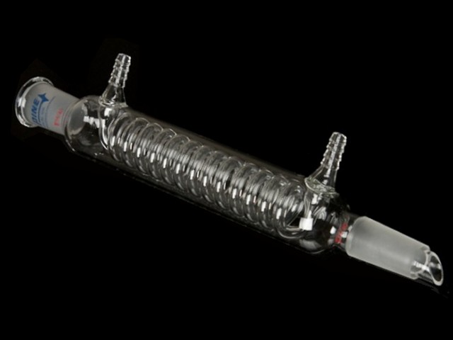 Glass Condenser (24/25 joint)
pH measurement,
Glass Condenser (24/25 joint)
pH measurement,
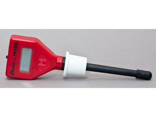 Compact pH Meter
thermowell,
Compact pH Meter
thermowell,
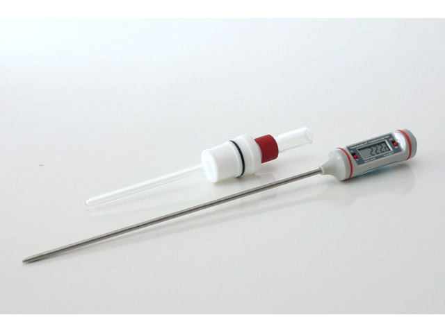 Digital Thermometer in Thermowell
each sold separately) while still having enough ports for the reference and counter electrodes.
Digital Thermometer in Thermowell
each sold separately) while still having enough ports for the reference and counter electrodes. - The OpenTop cell features a special recess in the bottom of the cell into which the lower end of the RCE shaft is inserted. This recess assists with aligning the shaft along the axis of the glass cell.
- Achievement of finer temperature control with a jacketed cell design.
- The one liter cell allows for larger solution volumes.
- A dual port purge accessory included with the cell permits the solution to be sparged and/or blanketed with a purge gas. In addition, the gas-purged bearing assembly
 Gas-Purged Bearing Assembly
(through which the rotating shaft enters the cell) has a separate purge port to allow a positive purge pressure to be maintained within the void space of the bearing itself.
Gas-Purged Bearing Assembly
(through which the rotating shaft enters the cell) has a separate purge port to allow a positive purge pressure to be maintained within the void space of the bearing itself.
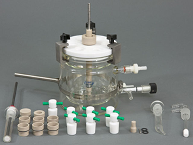
Figure 5. Components of the 15 mm OD RCE System
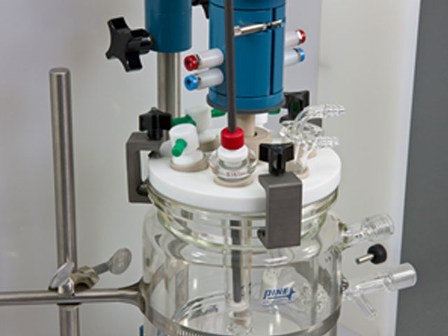
Figure 6. Assembled 15 mm OD RCE System with MSR Rotator
The following additional items are necessary to perform corrosion-based measurements:
- A potentiostat to measure corrosion current (e.g., Pine Research WaveDriver 100)
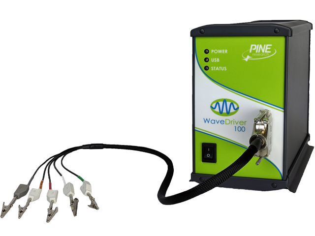 WaveDriver 100 EIS Potentiostat/Galvanostat
- An electrode rotator to achieve the desired wall shear stress (e.g., Pine Research MSR Electrode Rotator, see Figure 7)
 AFMSRCE Rotator
- Metal sample inserts for the RCE electrode (see Figure 2)
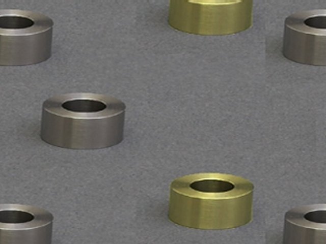 15 mm OD Cylinder Inserts
- A reference electrode for potentiostat control (e.g., Ag/AgCl, Saturated Calomel, Hg/Hg2SO4, or Hg/HgO)
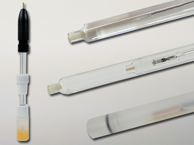 Standard Size Reference Electrodes
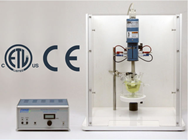
Figure 7. Pine Research MSR Rotator
9Appendix
9.1Appendix A - 15 mm OD RCE Technical Information and Data
The 15 mm OD RCE System uses a specially-designed RCE shaft and metals inserts. As shown in Figure 8, the shaft length is insulated with PEEK for higher temperature tolerance (up to 80°C). The metal cylinder insert fits onto the shaft between rubber O-ring seals and is secured with a screw cap. The black rubber O-rings ensure a tight seal to prevent solution leakage. The RCE shaft (15 mm OD) fits directly into a Pine Research MSR rotator.
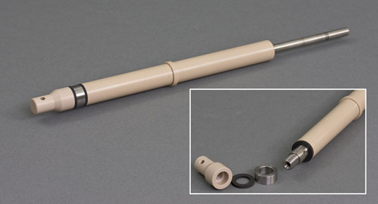
Figure 8. Assembled and Disassembled Views of the 15 mm OD Rotating Cylinder Electrode
The electrode shaft should never be cleaned or treated with acid. The shaft and internal hardware may corrode if exposed to corrosive solutions. Only use the RCE when fully assembled with seals, metal insert, and cap.
| Rotation Rate F (RPM) | Rotation Rate ω (rad/s) | Surface Velocity* Ucyl (cm/s) | Wall Sheer Stress* τcyl (g/cm s2) | Reynolds Number* RE (unitless) |
| 5 | 0.524 | 0.39 | 0.0035 | 66 |
| 10 | 1.047 | 0.79 | 0.0113 | 131 |
| 20 | 2.094 | 1.57 | 0.0366 | 263 |
| 50 | 5.236 | 3.93 | 0.1737 | 657 |
| 100 | 10.47 | 7.85 | 0.5642 | 1315 |
| 200 | 20.94 | 15.7 | 1.8332 | 2629 |
| 250 | 26.18 | 19.6 | 2.6789 | 3287 |
| 500 | 52.36 | 39.3 | 8.7039 | 6573 |
| 1000 | 104.7 | 78.5 | 28.279 | 13146 |
| 2000 | 209.4 | 157 | 91.879 | 26293 |
| 3000 | 314.2 | 236 | 183.05 | 39439 |
| 4000 | 418.9 | 314 | 298.52 | 52586 |
Table 1. Hydrodynamic Computations for a Typical* 15 mm OD Pine Research Rotating Cylinder Electrode in Water
| Pipe Velocity | Standard Schedule 40 Pipe Sizes (actual ID in cm) | |||||||||||
| (ft/s) | (cm/s) | (mi/hr) | 2 in (5.25 cm) |
4 in (10.23 cm) |
6 in (15.41 cm) |
8 in (20.27 cm) |
10 in (25.45 cm) |
12 in (30.32 cm) |
16 in (38.1 cm) |
18 in (42.88 cm) |
24 in (57.48 cm) |
|
| 0.1 | 3.0 | 0.07 | ||||||||||
| 0.2 | 6.1 | 0.14 | 23 | 21 | 19 | 18 | 18 | 17 | 16 | 16 | ||
| 0.3 | 9.1 | 0.2 | 39 | 34 | 32 | 30 | 29 | 28 | 27 | 26 | 25 | |
| 0.4 | 12.2 | 0.27 | 55 | 49 | 46 | 43 | 42 | 40 | 39 | 38 | 36 | |
| 0.5 | 15.2 | 0.34 | 73 | 65 | 60 | 57 | 55 | 53 | 51 | 50 | 48 | |
| 0.6 | 18.3 | 0.41 | 92 | 81 | 76 | 72 | 69 | 67 | 64 | 63 | 60 | |
| 0.7 | 21.3 | 0.48 | 111 | 99 | 92 | 87 | 84 | 81 | 78 | 76 | 72 | |
| 0.8 | 24.4 | 0.55 | 131 | 117 | 108 | 103 | 99 | 96 | 92 | 90 | 86 | |
| 0.9 | 27.4 | 0.61 | 152 | 135 | 126 | 120 | 115 | 111 | 107 | 105 | 99 | |
| 1.0 | 30.5 | 0.68 | 174 | 154 | 143 | 136 | 131 | 127 | 122 | 119 | 113 | |
| 2.0 | 61.0 | 1.36 | 413 | 366 | 341 | 324 | 311 | 302 | 290 | 284 | 269 | |
| 3.0 | 91.4 | 2.05 | 685 | 608 | 565 | 538 | 517 | 501 | 481 | 471 | 447 | |
| 4.0 | 122 | 2.73 | 982 | 871 | 810 | 771 | 741 | 718 | 689 | 675 | 640 | |
| 5.0 | 152 | 3.41 | 1298 | 1152 | 1071 | 1019 | 979 | 949 | 911 | 892 | 846 | |
| 6.0 | 183 | 4.09 | 1630 | 1447 | 1345 | 1280 | 1229 | 1192 | 1144 | 1120 | 1063 | |
| 7.0 | 213 | 4.77 | 1976 | 1754 | 1630 | 1552 | 1491 | 1445 | 1387 | 1358 | 1289 | |
| 8.0 | 244 | 5.45 | 2335 | 2073 | 1926 | 1834 | 1761 | 1707 | 1639 | 1605 | 1523 | |
| 9.0 | 274 | 6.14 | 2705 | 2401 | 2232 | 2125 | 2041 | 1978 | 1899 | 1859 | 1764 | |
| 10.0 | 305 | 6.82 | 3086 | 2739 | 2546 | 2425 | 2328 | 2256 | 2166 | 2121 | 2013 | |
| 11.0 | 335 | 7.50 | 3477 | 3086 | 2868 | 2731 | 2623 | 2542 | 2440 | 2389 | 2267 | |
| 12.0 | 366 | 8.18 | 3876 | 3441 | 3198 | 3045 | 2924 | 2834 | 2721 | 2664 | 2528 | |
| 13.0 | 396 | 8.86 | 3803 | 3534 | 3366 | 3232 | 3132 | 3007 | 2944 | 2794 | ||
| 14.0 | 427 | 9.55 | 3878 | 3692 | 3545 | 3436 | 3299 | 3230 | 3065 | |||
| 15.0 | 457 | 10.23 | 3865 | 3746 | 3596 | 3521 | 3341 | |||||
| 16.0 | 488 | 5.45 | 3898 | 3817 | 3622 | |||||||
| 17.0 | 518 | 11.59 | 3907 | |||||||||
| 18.0 | 549 | 12.27 | ||||||||||
Table 2. Rotation Rate Correlation for Water between a Typical* 15 mm Pine Research Rotating Cylinder Electrode and Smooth, Straight Pipe Flow.
9.2Appendix B - 12 mm OD RCE Technical Information and Data
Our classic 12 mm OD rotating cylinder electrodes have been used in oilfield corrosion inhibitor studies and other high velocity (high shear) corrosion experiments. While Pine Research will continue to support the 12 mm OD rotating cylinder electrode, new customers are encouraged to consider our integrated 15 mm OD RCE system instead. The 12 mm RCE design features a PTFE electrode shroud around the shaft connector with PTFE washers as shown in Figure 9. The 12 mm RCE tip fits an E3 series shaft
 Standard 12 mm RDE/RCE Shaft
for the MSR rotator or the permanently-installed shaft on the discontinued Pine Research CPR rotator. The 12 mm RCE tip is not compatible with the 15 mm RCE shaft.
Standard 12 mm RDE/RCE Shaft
for the MSR rotator or the permanently-installed shaft on the discontinued Pine Research CPR rotator. The 12 mm RCE tip is not compatible with the 15 mm RCE shaft.
 Precision 15 mm Single RCE Shaft
Standard 12 mm RDE/RCE Shaft
for the MSR rotator or the permanently-installed shaft on the discontinued Pine Research CPR rotator. The 12 mm RCE tip is not compatible with the 15 mm RCE shaft.
Precision 15 mm Single RCE Shaft
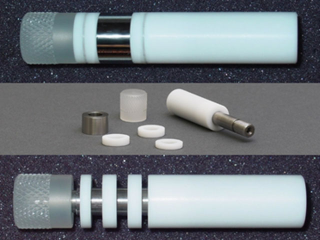
Figure 9. Assembled and Disassembled Views of the 12 mm OD Rotating Cylinder Electrode
The electrode shaft should never be cleaned or treated with acid. The shaft and internal hardware may corrode if exposed to corrosive solutions. Only use the RCE when fully assembled with seals, metal insert, and cap.
| Rotation Rate F (RPM) | Rotation Rate ω (rad/s) | Surface Velocity* Ucyl (cm/s) | Wall Sheer Stress* τcyl (g/cm s2) | Reynolds Number* RE (unitless) |
| 5 | 0.524 | 0.31 | 0.0025 | 42 |
| 10 | 1.047 | 0.63 | 0.0082 | 84 |
| 20 | 2.094 | 1.26 | 0.0267 | 169 |
| 50 | 5.236 | 3.14 | 0.1270 | 422 |
| 100 | 10.47 | 6.28 | 0.4125 | 844 |
| 200 | 20.94 | 12.6 | 1.3402 | 1688 |
| 500 | 52.36 | 31.4 | 6.3631 | 4219 |
| 1000 | 104.7 | 62.8 | 20.674 | 8438 |
| 2000 | 209.4 | 125.7 | 67.169 | 16876 |
Table 3. Hydrodynamic Computations for a Typical* 12 mm OD Pine Research Rotating Cylinder Electrode in Water
| Pipe Velocity | Standard Schedule 40 Pipe Sizes (actual ID in cm) | |||||||||||
| (ft/s) | (cm/s) | (mi/hr) | 2 in (5.25 cm) |
4 in (10.23 cm) |
6 in (15.41 cm) |
8 in (20.27 cm) |
10 in (25.45 cm) |
12 in (30.32 cm) |
16 in (38.1 cm) |
18 in (42.88 cm) |
24 in (57.48 cm) |
|
| 0.1 | 3.0 | 0.07 | ||||||||||
| 0.2 | 6.1 | 0.14 | 26 | |||||||||
| 0.3 | 9.1 | 0.2 | 44 | 39 | 36 | 34 | 33 | 32 | 31 | 30 | 29 | |
| 0.4 | 12.2 | 0.27 | 63 | 56 | 52 | 49 | 47 | 46 | 44 | 43 | 41 | |
| 0.5 | 15.2 | 0.34 | 83 | 74 | 68 | 65 | 63 | 61 | 58 | 57 | 54 | |
| 0.6 | 18.3 | 0.41 | 104 | 92 | 86 | 82 | 79 | 76 | 73 | 72 | 68 | |
| 0.7 | 21.3 | 0.48 | 126 | 112 | 104 | 99 | 95 | 92 | 89 | 87 | 82 | |
| 0.8 | 24.4 | 0.55 | 149 | 132 | 123 | 117 | 113 | 109 | 105 | 103 | 97 | |
| 0.9 | 27.4 | 0.61 | 173 | 153 | 143 | 136 | 130 | 126 | 121 | 119 | 113 | |
| 1.0 | 30.5 | 0.68 | 197 | 175 | 163 | 155 | 149 | 144 | 138 | 135 | 129 | |
| 2.0 | 61.0 | 1.36 | 469 | 416 | 387 | 368 | 354 | 343 | 329 | 322 | 306 | |
| 3.0 | 91.4 | 2.05 | 778 | 691 | 642 | 612 | 587 | 569 | 546 | 535 | 508 | |
| 4.0 | 122 | 2.73 | 1115 | 990 | 920 | 876 | 841 | 815 | 783 | 766 | 727 | |
| 5.0 | 152 | 3.41 | 1474 | 1308 | 1216 | 1158 | 1112 | 1078 | 1035 | 1013 | 961 | |
| 6.0 | 183 | 4.09 | 1851 | 1643 | 1527 | 1454 | 1397 | 1354 | 1299 | 1272 | 1207 | |
| 7.0 | 213 | 4.77 | 1993 | 1852 | 1764 | 1693 | 1641 | 1576 | 1543 | 1464 | ||
| 8.0 | 244 | 5.45 | 1939 | 1862 | 1823 | 1730 | ||||||
| 9.0 | 274 | 6.14 | ||||||||||
| 10.0 | 305 | 6.82 | ||||||||||
Table 4. Rotation Rate Correlation for Water between a Typical* 12 mm Pine Research Rotating Cylinder Electrode and Smooth, Straight Pipe Flow
10References
- Eisenberg, M.; Tobias, C. W.; Wilke, C. R. Ionic Mass Transfer and Concentration Polarization at Rotating Electrodes. Journal of The Electrochemical Society, 1954, 101(6), 306.
- Eisenberg, M.; Tobias, C. W.; Wilke, C. R. No title. Chemilca Engineering Progress Symposium Series, 1955, 51, 1.
- Gabe, D. R. The rotating cylinder electrode. J. Appl. Electrochem., 1974, 4(2), 91–108.
- Gabe, D. R.; Robinson, D. J. Mass transfer in a rotating cylinder cell—I. Laminar flow. Electrochim. Acta, 1972, 17(6), 1121–1127.
- Gabe, D. R.; Robinson, D. J. Mass transfer in a rotating cylinder cell—II. Turbulent Flow. Electrochim. Acta, 1972, 17(6), 1129–1137.
- Gabe, D. R.; Walsh, F. C. The rotating cylinder electrode: a review of development. J. Appl. Electrochem., 1983, 13(1), 3–21.
- Gabe, D. R.; Walsh, F. C. Enhanced mass transfer at the rotating cylinder electrode. I. Characterization of a smooth cylinder and roughness development in solutions of constant concentration. J. Appl. Electrochem., 1984, 14(5), 555–564.
- Gabe, D. R.; Walsh, F. C. Enhanced mass transfer at the rotating cylinder electrode. II. Development of roughness for solutions of decreasing concentration. J. Appl. Electrochem., 1984, 14(5), 565–572.
- Gabe, D. R.; Walsh, F. C. Enhanced mass transfer at the rotating cylinder electrode: III. Pilot and production plant experience. J. Appl. Electrochem., 1985, 15(6), 807–824.
- Gabe, D. R.; Makanjuola, P. A. Enhanced mass transfer using roughened rotating cylinder electrodes in turbulent flow. J. Appl. Electrochem., 1987, 17(2), 370–384.
- Gabe, D. R.; Wilcox, G. D.; Gonzalez-Garcia, J.; Walsh, F. C. The rotating cylinder electrode: its continued development and application. J. Appl. Electrochem., 1998, 28(8), 759–780.
- Kear, G.; Barker, B. D.; Stokes, K.; Walsh, F. C. Flow influenced electrochemical corrosion of nickel aluminium bronze – Part II. Anodic polarisation and derivation of the mixed potential. J. Appl. Electrochem., 2004, 34(12), 1241–1248.
- Kear, G.; Barker, B. D.; Stokes, K.; Walsh, F. C. Flow influenced electrochemical corrosion of nickel aluminium bronze – Part I. Cathodic polarisation. J. Appl. Electrochem., 2004, 34(12), 1235–1240.
- Lu, Q.; Stack, M. M.; Wiseman, C. R. AC impedance spectroscopy as a technique for investigating corrosion of iron in hot flowing Bayer liquors. J. Appl. Electrochem., 2001, 31(12), 1373–1379.
- Maciel, J. M.; Agostinho, S. M. L. Use of a rotating cylinder electrode in corrosion studies of a 90/10 Cu-Ni alloy in 0.5 M L-1 H2SO4 media. J. Appl. Electrochem., 2000, 30(8), 981–985.
- Meštrović-Markovinović, A.; Matić, D. Mass transfer to a rotating horizontal cylinder electrode with full and partial immersion. J. Appl. Electrochem., 1984, 14(5), 675–678.
- Grau, J. M.; Bisang, J. M. Mass transfer studies at rotating cylinder electrodes of expanded metal. J. Appl. Electrochem., 2005, 35(3), 285–291.
- Eklund, A.; Simonsson, D. Enhanced mass transfer to a rotating cylinder electrode with axial flow. J. Appl. Electrochem., 1988, 18(5), 710–714.
- Labraga, L.; Bourabaa, N.; Berkah, T. Wall shear stress from a rotating cylinder in cross flow using the electrochemical technique. Exp. Fluids, 2002, 33(3), 488–496.
- Efird, K. D.; Wright, E. J.; Boros, J. A.; Hailey, T. G. Correlation of steel corrosion in pipe flow with jet impingement and rotating cylinder tests. Corrosion, 1993, 49(12), 992–1003.
- Silverman, D. C. Rotating Cylinder Electrode for Velocity Sensitivity Testing. Corrosion, 1984, 40(5), 220–226.
- Silverman, D. C.; Zerr, M. E. Application of the Rotating Cylinder Electrode—E-Brite 26-1/Concentrated Sulfuric Acid. Corrosion, 1986, 42(11), 633–640.
- Silverman, D. C. Rotating Cylinder Electrode-Geometry Relationships for Prediction of Velocity-Sensitive Corrosion. Corrosion, 1988, 44(1), 42–49.
- Silverman, D. C. Corrosion prediction in complex environments using electrochemical impedance spectroscopy. Electrochim. Acta, 1993, 38(14), 2075–2078.
- Kalota, D. J.; Silverman, D. C. Behavior of Aspartic Acid as a Corrosion Inhibitor for Steel. Corrosion, 1994, 50(2), 138–145.
- Silverman, D. C. Technical Note: On Estimating Conditions for Simulating Velocity-Sensitive Corrosion in the Rotating Cylinder Electrode. Corrosion, 1999, 55(12), 1115–1118.
- Silverman, D. C. Technical Note: Simplified Equation for Simulating Velocity-Sensitive Corrosion in the Rotating Cylinder Electrode at Higher Reynolds Numbers. Corrosion, 2003, 59(3), 207–211.
- Silverman, D. C. The Rotating Cylinder Electrode for Examining Velocity-Sensitive Corrosion—A Review. Corrosion, 2004, 60(11), 1003–1023.
- Silverman, D. C. Technical Note: Conditions for Similarity of Mass-Transfer Coefficients and Fluid Shear Stresses between the Rotating Cylinder Electrode and Pipe. Corrosion, 2005, 61(6), 515–518.
- Levich, V. G. Physicochemical hydrodynamics, 1st ed. Prentice-Hall: Englewood Cliffs, NJ, 1962.
- Holser, R. A.; Prentice, G.; Pond, R. B.; Guanti, R. Use of Rotating Cylinder Electrodes to Simulate Turbulent Flow Conditions in Corroding Systems. Corrosion, 1990, 46(9), 764–769.
- Chen, T. Y.; Moccari, A. A.; Macdonald, D. D. Development of Controlled Hydrodynamic Techniques for Corrosion Testing. Corrosion, 1992, 48(3), 239–255.
- Nesic, S.; Solvi, G. T.; Skejerve, S. Comparison of rotating cylinder and loop methods for testing CO2 corrosion inhibitors. Br. Corros. J., 1997, 32(4), 269–276.
- ASTM G170-01a Standard Guide for Evaluating and Qualifying Oilfield and Refinery Corrosion Inhibitors in the Laboratory. In ASTM International ATSM International: West Conshohocken, PA, 2012.
- ASTM Editors ASTM G185-06 Standard Practice for Evaluating and Qualifying Oil Field and Refinery Corrosion Inhibitors Using the Rotating Cylinder Electrode ATSM International: West Conshohocken, PA, 2012.