


Exploring Faraday’s Law Using Inexpensive Screen-Printed Electrodes
Last Updated: 11/1/19 by Alex Peroff
Download as PDF1Abstract
This post describes an experimental procedure for the general chemistry laboratory student that conveniently illustrates the electroplating process.
 Bard, A. J.; Faulkner, L. A. Electrochemical Methods: Fundamentals and Applications, 2nd ed. Wiley-Interscience: New York, 2000.
Chuan, Y.; Chyan, O. Metal Electrodeposition on an Integrated, Screen-Printed Electrode Assembly. J. Chem. Educ., 2008, 85(4), 565. Students plate a thin film of nickel on to a screen-printed carbon electrode. The plating process is accurately controlled using a traditional three-electrode electrochemical cell arrangement. Each screen-printed electrode pattern includes all three required electrodes (working, reference, and counter). Nickel is plated onto the working electrode from a conventional Watts nickel plating solution. The light weight electrode pattern is massed before and after deposition of the metal. By massing the patterned electrode before and after deposition, the student obtains the mass of nickel actually deposited on to the working electrode. This mass result used with Faraday’s Law allows the student to compute the efficiency of the electrodeposition process.
Chuan, Y.; Chyan, O. Metal Electrodeposition on an Integrated, Screen-Printed Electrode Assembly. J. Chem. Educ., 2008, 85(4), 565. Students plate a thin film of nickel on to a screen-printed carbon electrode. The plating process is accurately controlled using a traditional three-electrode electrochemical cell arrangement. Each screen-printed electrode pattern includes all three required electrodes (working, reference, and counter). Nickel is plated onto the working electrode from a conventional Watts nickel plating solution. The light weight electrode pattern is massed before and after deposition of the metal. By massing the patterned electrode before and after deposition, the student obtains the mass of nickel actually deposited on to the working electrode. This mass result used with Faraday’s Law allows the student to compute the efficiency of the electrodeposition process.
2Introduction
Electroplating is an important branch of electrochemistry with many applications in modern technology. For example, the automobile industry relies upon nickel and chromium electroplating to protect steel from corrosion. Noble metal electroplating of the coinage metals (see Figure 1) is used for decorative purposes such as fabricating jewelry. Electroplating is also an essential tool for manufacturing state-of-the-art electronic devices. Electrodeposited copper metal interconnects within integrated circuits play an important role in the devices used to build the information superhighway. In this lab experiment, basic principles of electroplating are explored by plating thin films of nickel onto screen-printed carbon electrodes.
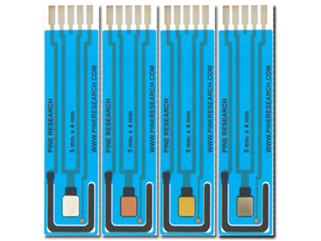
Figure 1. Screen-Printed Carbon Electrodes with Nickel, Copper, Gold, and Silver (left to right)
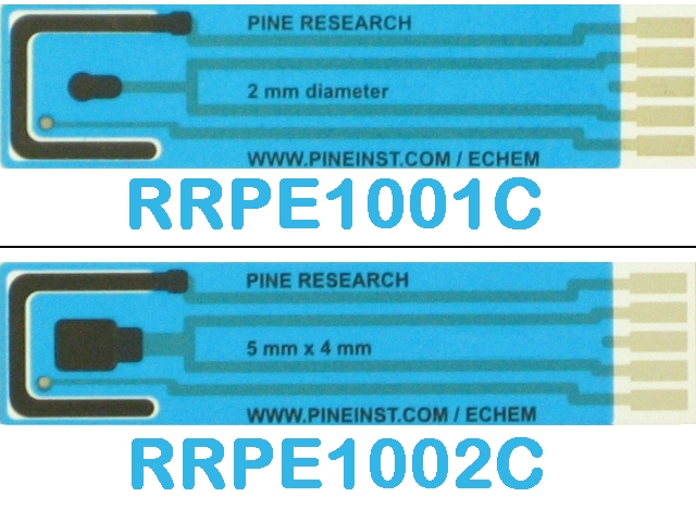
This laboratory experiment makes use of inexpensive screen-printed electrodes (SPEs)
 Carbon Screen-Printed Electrodes
as a convenient (and disposable) alternative to larger-sized bulk metal electrodes. Each electrode consists of a carbon working electrode (WE), a carbon counter electrode (CE), and a silver/silver chloride reference electrode (REF). The student voltammetry cell (see Figure 2) is ideal for vertically-mounting the SPE, thereby making observation of the plating process easy to visualize.
Carbon Screen-Printed Electrodes
as a convenient (and disposable) alternative to larger-sized bulk metal electrodes. Each electrode consists of a carbon working electrode (WE), a carbon counter electrode (CE), and a silver/silver chloride reference electrode (REF). The student voltammetry cell (see Figure 2) is ideal for vertically-mounting the SPE, thereby making observation of the plating process easy to visualize.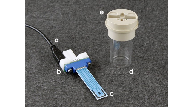
Figure 2. Compact Voltammetry Cell Components: (a) USB-Style Cell Cable; (b) Cell Grip Mount; (c) Screen-Printed Electrode (SPE); (d) Scintillation Vial; and (e) Cap
For accurate control of the electrode potential used for electroplating, it is recommended that the working, counter, and reference electrodes be connected to a modern three-electrode potentiostat (such as the Pine Research WaveNow).
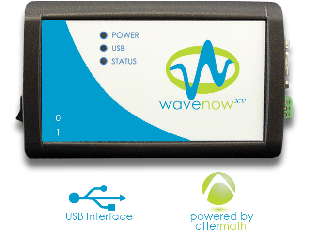 WaveNowXV Potentiostat Bundles
Such potentiostats are capable of applying and maintaining a constant potential between the working and reference electrodes while at the same time accurately measuring the flow of charge (current) through the working electrode.
WaveNowXV Potentiostat Bundles
Such potentiostats are capable of applying and maintaining a constant potential between the working and reference electrodes while at the same time accurately measuring the flow of charge (current) through the working electrode.
WaveNowXV Potentiostat Bundles
Such potentiostats are capable of applying and maintaining a constant potential between the working and reference electrodes while at the same time accurately measuring the flow of charge (current) through the working electrode. 3Background
As the potential of working electrode moves toward more negative values, electrons at the working electrode surface become more readily available to reduce ions in the solution. Nickel(II) cations in solution are reduced to nickel metal.
The standard half-cell reaction for this process can be described as follows:
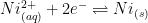 |
(1) |
The reduction potential for Ni(II) (see Equation 1) is E0 = -0.25 V vs. SHE. Under acidic plating conditions (pH = 3), the reduction of hydronium (H+) to form hydrogen gas is the main side reaction that consumes additional electrical charge (see Equation 2).
 |
(2) |
In electrochemistry, the reduction potential of hydronium is arbitrarily set to zero; i.e., E0 = 0 V vs. SHE. Faraday’s law states that the extent of chemical reaction (i.e., mass of electroplating metal, m) caused by the flow of current is proportional to the amount of electric charge (Q, in Coulombs) passed through the electrochemical cell (see Equation 3).
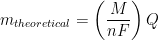 |
(3) |
In Equation 3, M is the molar mass of the deposited metal, n is the number of electrons transferred in the reaction (oxidation state of the metal ion), and F is Faraday’s Constant (96,485 C/mol). It is common to simplify Equation 3 by introducing a new term, Z, called the electrochemical equivalent, which is a constant of proportionality (see Equation 4).
 |
(4) |
Therefore, the electrochemical equivalent, Z, for the case of electroplating of Ni from Ni2+ solution is 3.041 x 10⁻⁴ g/C. This value means that consumption of one coulomb (C) of electric charge can electrodeposit a maximum of 3.041 x 10⁻⁴ g of nickel onto the cathode. Side reactions often reduce the overall electroplating current efficiency below 100%.
One can calculate the electrodeposition (plating) efficiency (W) by taking the ratio of actual mass plated and theoretical mass plated (see Equation 5).
 |
(5) |
The actual plating efficiency is always less than 100% due to various unwanted side reactions that also occur, consuming additional electric charge.
4 Chemicals
4.1Plating Solution
Prepare 1 L of standard Watts nickel plating solution as follows: add 290 g nickel sulfate hexahydrate (NiSO4 • 6H2O), 30.0 g of boric acid (H3BO3), and 8 g of sodium chloride (NaCl) to a 1 L volumetric flask and dilute to the mark with distilled water. This nickel plating solution is rather stable.
4.2Initial Mass Measurements
Subsequent analytical calculations depend on accurate initial measurements. The screen-printed electrode must be massed prior to experimentation to determine the mass of nickel plated.
Rinse the SPE with deionized water. Allow to dry. You can speed up the drying process by gently dabbing the SPE with a lab wipe or blowing a light stream of N2 over the surface of the SPE.
After the electrode has dried, mass the entire SPE on a tared analytical balance. Record the mass to four significant digits (if available) in your notebook as the initial mass of the SPE.
4.3Electroplating Procedure
The cell (see Figure 2) should be filled with approximately 10 mL of Watts plating solution. Insert the SPE into the cell grip mount (the cell grip mount is two-sided, allowing SPE electrodes to be loaded in either direction). Use between one to two spacers on the backside of the SPE to ensure the electrode is held tightly in place. Place the grip mount loaded with the SPE into the cell cap and connect to the vial containing the Watts plating solution. Connect the electrode to the potentiostat. When viewing the blue surface facing downwards, connect the mini-USB-style plug to the receptacle to the left of the SPE face.
Create a “Bulk Electrolysis (BE)” experiment in AfterMath.
 Bulk Electrolysis (BE)
Set the parameters to apply a negative potential (-1.2 V) to the carbon working electrode for 60 minutes (see Figure 3). The potential of the working electrode is held constant with respect to the Ag/AgCl reference electrode during the electrolysis experiment. This means the electrode potential is 1.2 V more negative than the potential of the silver/silver chloride reference electrode. This potential is sufficiently negative (cathodic) to cause nickel ions in the plating solution to be reduced to metallic nickel at the surface of the carbon working electrode; thus, nickel naturally forms a thin film on the electrode surface.
Bulk Electrolysis (BE)
Set the parameters to apply a negative potential (-1.2 V) to the carbon working electrode for 60 minutes (see Figure 3). The potential of the working electrode is held constant with respect to the Ag/AgCl reference electrode during the electrolysis experiment. This means the electrode potential is 1.2 V more negative than the potential of the silver/silver chloride reference electrode. This potential is sufficiently negative (cathodic) to cause nickel ions in the plating solution to be reduced to metallic nickel at the surface of the carbon working electrode; thus, nickel naturally forms a thin film on the electrode surface.
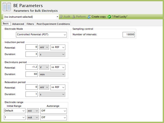
Figure 3. AfterMath Bulk Electrolysis Parameters
Observe the working electrode surface at regular intervals during the electrolysis. During the early minutes of the plating process, you should observe white nickel gradually covering the black carbon working electrode surface. Record observations in your notebook and include the electrolysis duration time that has elapsed when making these observations.
AfterMath will monitor the current at the working electrode throughout the plating procedure. The current is a measure of how fast the electrons flow from the working electrode and reduce chemical species in the solution, including but not limited to, the nickel cations.
Initially, you will observe a larger current that fairly rapidly decays (exponentially). As more nickel ions are reduced to the electrode surface, the solution around the working electrode becomes depleted of additional nickel. Therefore, the current, a measure of electron transfer at the working electrode (reduction of nickel ion to nickel metal), will decay slowly over time. When left long enough, no additional nickel would plate onto the electrode unless the solution was stirred.
4.4Post-Plating Mass Measurement
After an hour of electrolysis, there should have formed a visibly thick layer of nickel on the working electrode surface. Carefully remove the SPE from the compact voltammetry cell and dry the electrode as before, being careful with a lab wipe. The ideal method to dry the surface is with a gentle stream of N2 gas or compressed air. After the electrode is dried, obtain the mass of the SPE on a tared analytical balance. Record the mass to four significant digits (if available) in your notebook as the final mass of the SPE.
5Electrochemical Data
As described, during a constant potential bulk electrolysis, current is measured as a function of time. Your data will resemble a typical chronoamperogram (see Figure 4).
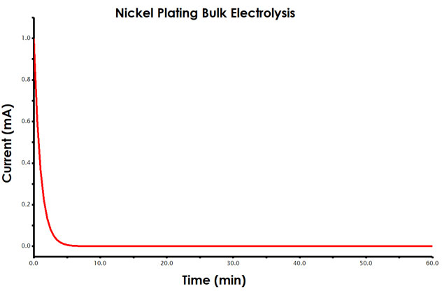
Figure 4. Current vs. Time Plot (Chronoamperogram) for Bulk Electrolysis Experiment
From Faraday’s law, you know that the total amount of charge passed during an electrolysis is proportional to the mass of metal reduced at the working electrode surface (see Equations 3-5). During analysis, you will determine the charge passed during the total electrolysis using AfterMath tools.
6Analysis
6.1Electrodeposition Mass
Calculate the mass of nickel plated to the electrode surface. Record this value in your notebook.
6.2Charge Determination
Find the amount of charge passed during the electrolysis. This can be accomplished in AfterMath. The first step in analyzing your results is to obtain the charge data from the chronoamperogram. Charge is the area beneath the current vs. time plot. Current has the unit of amperes (A), where 1 A = 1 coulomb/second (C/s). If you were to multiply each current measurement by the elapsed time (C/s x S = C) and sum the charge across the entire experiment, you would determine the total charge passed during electrolysis.
The AfterMath software provides an easy way to measure charge from a chronoamperogram, using the area tool (see Figure 5). Measure the charge (area) for your nickel plating electrolysis. Record the total charge in your notebook.
It may take some time to become familiar with the tools in AfterMath. Consult with your instructor if you have any difficulties using the tools to determine charge.
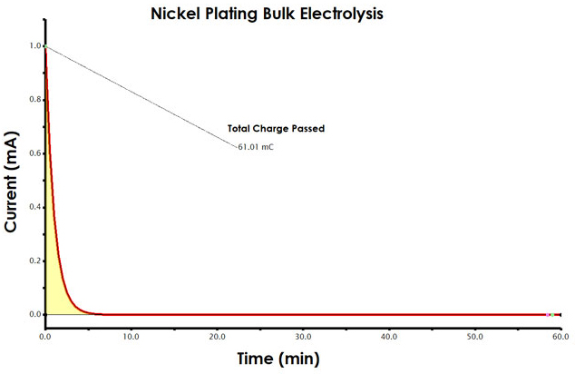
Figure 5. Determination of Charge from a Chronoamperogram in AfterMath
6.3Calculate Electrodeposition Efficiency
For the final calculation, you will have to combine all pieces of data collected thus far. Review Section 3 to gain familiarity with Faraday’s law. Pay attention to units. Calculate the electrodeposition efficiency using Equation 5.
7Report Questions
- What is the color of nickel metal? When two electrons are removed from nickel, what color will result?
- Did you observe anything on the surface of the electrode as the potential was applied and the deposition occurred? What did you see and what do you think it could be? (Hint: A molecule of water is composed of two atoms of hydrogen and one atom of oxygen)
- Was your average plating efficiency less than or greater than one hundred percent? Why do you think that this was the case?