 This article is adapted from Section 6 of the User Manual for the Pine Modulated Speed Rotator (MSR).
Related Links: MSR User Manual, MSR Rotator Support Page, Pine Research Instrumentation
Table of Contents
6.1 Routine Cleaning
Regular maintenance of the rotator primarily consists of keeping the external surfaces of the system clean by wiping them with a towel moistened with water or a mild, non-abrasive cleaner.
After about two weeks of continuous use, open the brush chamber and vacuum out any dust or debris. If necessary, remove the lower bearing assembly for better access to the brush chamber (see Section 6.3), and use a towel moistened with water or a mild, non-abrasive cleaner to clean the inner surfaces of the brush chamber.
The electrode brushes may deposit silver-carbon dust inside the brush chamber and deposit a film on the surface of the rotating shaft. A thin film on the shaft actually improves the contact between the brush and the shaft. This film does not need to be cleaned off of the shaft unless the film is rough or bumpy.
6.2 Brush Replacement
The brushes contact the rotating shaft, slowly wearing during normal use, and periodically, the brushes must be replaced. A simple brush replacement kit is available, or in the case of serious damage to the entire brush assembly, the brush and its PTFE holder can be replaced.
6.2.1 Internal Brush Replacement
Rotating shaft. Entanglement hazard.
Turn off the power to the rotator and disconnect the power cord from the power source before continuing with this procedure.
AVERTISSEMENT:
Arbre en rotation. Danger d’enchevêtrement.
Éteignez le rotateur et débranchez le cordon d’alimentation de la source d’alimentation avant de poursuivre cette procédure.
- The standard brush replacement kit contains a small hex key, a new brush, and a new set screw (installed in the brush).
A special brush replacement kit should be used when the rotator is routinely operated in low humidity conditions such as inside a glove box.
Part numbers for brush replacement kits are listed in Section 7.1. - Remove the entire brush assembly from the rotator by unscrewing it as shown below. It should be possible to remove the brush assembly by hand.
- Use the small hex key to remove the set screw. Note that the required hex key (
) is included with the brush replacement kit.
- After removing the set screw, remove and discard the old brush, but do not discard the empty brush holder.
- The new replacement brush includes a set screw which is already installed.
- Temporarily remove this set screw.
- Be careful not to misplace the set screw.
- Carefully slide the new spring-loaded brush into the brush holder.
Be careful to properly align the set screw hole with the slot on the side of the brush holder. - While squeezing the new brush into the brush holder, use the hex key to reinstall the set screw.
Tighten the set screw until it stops turning. - Reinstall the brush assembly by threading it back into the side of the rotator.
Hand-tighten the brush assembly. Do not use tools to tighten the assembly.
6.2.2 Complete Brush Assembly Replacement
In the event that the main body of the brush assembly is damaged, it may be necessary to replace the entire brush assembly.
Rotating shaft. Entanglement hazard.
Turn off the power to the rotator and disconnect the power cord from the power source before continuing with this procedure.
AVERTISSEMENT:
Arbre en rotation. Danger d’enchevêtrement.
Éteignez le rotateur et débranchez le cordon d’alimentation de la source d’alimentation avant de poursuivre cette procédure.
- Remove the old brush assembly from the rotator by unscrewing it as shown below.
- Remove the old brush assembly by hand. (Use tools only if necessary!)
- Install the new brush assembly by threading it by hand into the side of the rotator. Do not use tools to tighten the brush assembly.
6.3 Lower Bearing Replacement
The lower bearing assembly is a common replacement item due to mechanical wear and also due to exposure to corrosive vapors from the cell solution. The standard lower bearing assembly contains a stainless steel bearing which is generally resistant to corrosive attack. In laboratories where particularly corrosive solutions are used, an assembly based on a ceramic bearing can be used instead. Part numbers for bearing assemblies are listed in Section 7.1.
Rotating shaft. Entanglement hazard.
Turn off the power to the rotator and disconnect the power cord from the power source before continuing with this procedure.
AVERTISSEMENT:
Arbre en rotation. Danger d’enchevêtrement.
Éteignez le rotateur et débranchez le cordon d’alimentation de la source d’alimentation avant de poursuivre cette procédure.
- Disconnect the motor control cable from the connector on top of the motor unit. If there is a shaft presently installed the motor unit, remove the shaft. Disconnect any signal cables from the brush banana jacks (red and blue).
Use a flathead screwdriver to loosen the four screws that secure the lower bearing assembly to the motor unit. As you are loosening the final screw with one hand, catch the bearing assembly with your other hand. - Align the four screw holes on the new bearing assembly with the four threaded holes in the motor unit.
- Thread the four screws into the holes by hand. Then, tighten the screws with a flathead screwdriver.
6.4 Removing the Motor-Coupling Assembly
On rare occasions (such as when replacing a failed motor), it may be necessary to remove the motor-coupling assembly from the motor unit.
Rotating shaft. Entanglement hazard.
Turn off the power to the rotator and disconnect the power cord from the power source before continuing with this procedure.
AVERTISSEMENT:
Arbre en rotation. Danger d’enchevêtrement.
Éteignez le rotateur et débranchez le cordon d’alimentation de la source d’alimentation avant de poursuivre cette procédure.
- Disconnect the motor control cable from the top of the motor unit.
- If there is a shaft presently installed in the motor unit, remove the shaft.
- Disconnect any signal cables from the brush banana jacks (red and blue).
- There are two screws which hold the cowling in place (front and back). Use a flathead screwdriver to remove these two screws from the cowling.
- Carefully begin removing the cowling from the motor unit. The internal cable assembly will prevent the cowling from being completely removed. However, there is a junction in the middle of the internal cable assembly where two white connectors are joined together. By disconnecting the cable assembly at this junction, it is possible to remove the cowling completely. Disconnect the junction by releasing the locking mechanism that holds the connectors together.
- The internal cables are secured to the motor using two plastic cable ties. In order to remove the motor, the lower cable tie must be cut and removed.
- There are four screws which hold the motor in place.
- Using a flathead screwdriver, loosen and remove these four screws.
- As the fourth and final screw is being removed, be sure to support the motor and brush chamber from below to prevent damage from a sudden fall.
- Carefully lower the motor out of the support while guiding the fragile motor and tachometer cables through the support.
- Carefully separate the motor from the brush chamber.
CAUTION:
DO NOT REMOVE the upper cable tie. The upper cable tie protects the fragile connections to the motor.
ATTENTION:
NE RETIREZ PAS l’attache de câble supérieure.
L’attache de câble supérieure protège les câbles fragiles de connexion au
moteur.
The red (positive) and black (negative) lines are connected to the tachometer, and the white (positive) and green (negative) lines are connected to the motor.
6.5 Installing a New Motor-Coupling Assembly
After removing the old motor-coupling assembly (see Section 6.4), a new motor-coupling assembly may be installed.
![]() CAUTION:
CAUTION:
After installing a new motor, it is necessary to recalibrate the rotation rate using an optical tachometer (see Section 6.6).
ATTENTION:
Après l’installation d’un nouveau moteur, il est nécessaire de recalibrer la vitesse de rotation à l’aide d’un tachymètre optique (voir Section 6.6).
Rotating shaft. Entanglement hazard.
Turn off the power to the rotator and disconnect the power cord from the power source before continuing with this procedure.
AVERTISSEMENT:
Arbre en rotation. Danger d’enchevêtrement.
Éteignez le rotateur et débranchez le cordon d’alimentation de la source d’alimentation avant de poursuivre cette procédure.
- Disconnect the motor control cable from the top of the motor unit.
- Disconnect any signal cables from the brush banana jacks (red and blue).
- Examine the new motor coupling unit.
- Examine the new motor coupling unit. There should be one cable tie securing the cables to the motor (black) as shown below. Do not remove this cable tie.
- Remove any extra cable ties (i.e., around the green part of the motor) so that the cable can move freely.
- Align the threaded holes in the new motor with those in the brush chamber and push the motor up into the support. Carefully feed the cables through the hole as shown in the figure below.
- Perform the following:
- Secure the motor and chamber to the support using four screws.
- Connect the internal cable within the cowling to the motor by joining the two white connectors together.
- Replace the cowling on top of the motor and secure it with two screws.
Motor Control Cable Wiring
The motor control cable is a 15-conductor cable that is wired “straight thru” from a male HD-15 connector on one end to a female HD-15 connector on the other end. Although there are 15 conductors, only four signals actually travel through the cable, and several conductors are grouped together (see Table 6.1). The HD-15 connector on top of the motor unit connects (internally) with the motor wiring harness which has four colored signal wires (see Table 6.2).
 |
|
| pins | description |
| 1-4 | Motor Supply (-) |
| 6-9 | Motor Supply (+) |
| 11-12 | Tachometer (+) |
| 13-14 | Tachometer (-) |
Table 6.1: Motor Control Cable Wiring
 |
|
| wire color | description |
| green | Motor Supply (-) |
| white | Motor Supply (+) |
| red | Tachometer (+) |
| black | Tachometer (-) |
Table 6.2: Internal Motor Cable Wiring
6.6 Rotation Rate Calibration
The rotation rate is controlled by a tunable analog feedback circuit located inside the control unit. This circuit is tuned and calibrated at the factory prior to shipment, but if the rotator needs to be recalibrated by the owner at a later date, the procedure below describes the best method for calibrating and verifying the rotation rate control circuit.
The most important tool required for calibrating the rotator is a non-contact optical tachometer. Pine offers such a simple tachometer (see Figure 6.1) as part of the MSR Calibration Kit, and this simple tachometer is suitable for routine verification or calibration of the rotation rate by the owner. The MSR Calibration Kit is sold separately (see Section 7.1 for part number).
In the event that the rotation rate must be rigorously traceable to a national or international standards organization, a more sophisticated and professional tachometer with traceable certification should be used (see Figure 6.2). When a rotator is manufactured at the factory (or when a rotator is returned to the factory for service), recalibration is performed using a traceable tachometer.
The tachometer reads the rotation rate when it is pointed at a rotating shaft equipped with a reflective target (see Figure 6.3). The MSR Calibration Kit includes a shaft suitable for use as a target. Alternately, a stainless steel rod (;
) may be mounted in the motor coupling, and a mark can be made on the rod with a marker.
Figure 6.1: Rotator Calibration Toolkit (including simple handheld tachometer)
Figure 6.2: Professional Optical Tachometer with Traceable Calibration
Figure 6.3: Use of Optical Tachometer with Reflective Target
The calibration process involves making adjustments to various trimmer potentiometers (trimmers) on the circuit board. The MSR Calibration Kit includes a trimmer adjustment tool for this purpose. Alternately, a small flathead screwdriver can be used to make these adjustments.
A calibrated digital voltmeter is required to confirm certain signal levels on the circuit board. It is recommended that a digit voltmeter be used for this purpose. The calibration process also requires a known voltage source (
). This known source can be a power supply or waveform generator, and the value of the known voltage (
) should be verified using the calibrated digital voltmeter.
Other tools required are a medium sized Phillips screwdriver (to remove the top panel of the control unit) and a small () hex key (to turn the hex screws on the motor coupling when installing or removing a shaft). The hex key is included with the purchase of a new rotator and it is also available at many retail hardware supply stores.
6.6.1 Detailed Calibration Procedure
DANGER:
High voltage. Risk of electric shock.
This procedure must be performed by an electrician or a qualified technician. This procedure requires working inside the control unit while the control unit is powered on and operating.
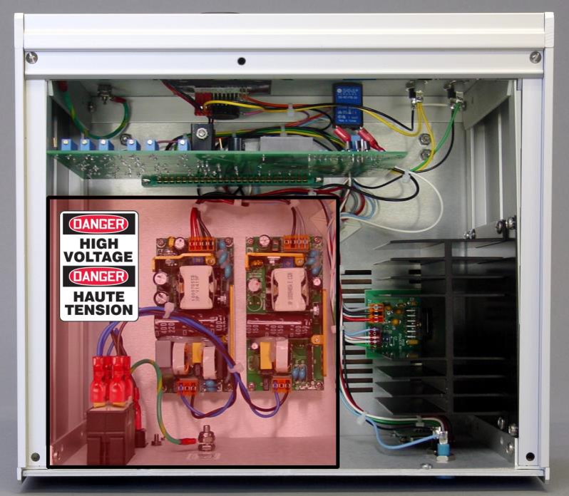
High voltages are present inside the control unit at the power entry module and on the two internal power supply modules as shown in the shaded and outlined portion of the image below.
KEEP HANDS AND TOOLS AWAY FROM THE POWER ENTRY MODULE AND THE TWO POWER SUPPLY MODULES!
DANGER:
Haute Tension. Risque de décharge électrique.
Cette procédure doit être confiées à un électricien ou un technicien qualifié. Cette procédure requiert de travailler à l’intérieur de l’unité de commande lorsque cette dernière est alimentée et en fonctionnement.
Des tensions élevées sont présentes dans l’unité de commande au niveau du module d’entrée d’alimentation et sur les deux modules d’alimentation internes tel qu’indiqué dans la portion grisée et mise en évidence de l’image ci-dessous.
GARDEZ VOS MAINS ET VOS OUTILS ÉLOIGNÉS DU MODULE D’ENTRÉE D’ALIMENTATION ET DES DEUX MODULES D’ALIMENTATION!
CAUTION:
Static electricity may damage electronic components.
Ensure proper grounding when handling static sensitive components by wearing a grounding strap.
ATTENTION:
L’électricité statique est susceptible d’endommager les composants électriques.
Veillez à disposer d’une mise à la terre appropriée lorsque vous manipulez des composants sensibles en portant un ruban de mise à la terre.
When performing a traceable rotation rate calibration, verify the dates on the calibration certificates for the tachometer and voltmeter and confirm that the certificates have not expired.
- Switch off power to the rotator and disconnect the power cord.
- With the power cord disconnected, remove the cover from the control unit.
- While the power is switched off, note the positions of the various trimmers located along the top of the main circuit board.
- A trimmer adjustment tool (or a flathead screwdriver) is required to adjust these trimmers.
- While the power is switched off, install the tachometer target into the motor coupling on the motor unit.
- This target should be a metal rod with the appropriate diameter (
or
).
- Many tachometers require that a piece of reflective tape be attached to the end of the shaft as shown.
- This target should be a metal rod with the appropriate diameter (
- Turn the rotation rate knob fully counter-clockwise. This is the position which corresponds to a nearly zero rotation rate.
- Reconnect the power cord and carefully switch on the rotator.
- Using the tachometer to monitor the actual rotation rate, slowly adjust the rotation rate knob on the front panel until the tachometer indicates a rotation rate of approximately
.
- After the one hour waiting period, turn the rotation rate knob fully counter-clockwise. This is the position which corresponds to a nearly zero rotation rate.
- Locate testpoints TP2 and TP3 on the circuit board.
- These testpoints are accessible without the need to remove the circuit board from the control unit.
- Connect the black lead of the digital voltmeter to one of the two black banana jacks (DC common) on the front panel of the control unit.
- Connect the red lead of the digital voltmeter to testpoint TP3 on the circuit board.
- Adjust trimmer P3 until the voltmeter reads
.
- Adjust trimmer P3 until the voltmeter reads
- Connect the red lead of the digital voltmeter to testpoint TP2 on the circuit board and keep it connected to perform the following steps.
- Adjust trimmer P2 until the voltmeter reads
.
- Adjust trimmer P3 until the voltmeter reads approximately
.
- At this point, the motor should be rotating at a very slow rate. The direction of this slow rotation should be counterclockwise when looking down on the motor unit from above.
- Adjust trimmer P2 until the voltmeter reads
- Turn the rotation rate control knob very slowly until the motor comes to a complete stop.
- Adjust trimmer P7 until the rotation rate display on the front panel reads
.
- Connect the red lead of the digital voltmeter to the OUTPUT signal jack on the front panel. Confirm that the signal level at this jack is
.
- Using the tachometer to monitor the actual rotation rate, slowly adjust the rotation rate knob on the front panel until the tachometer indicates a rotation rate of
.
- Adjust trimmer P7 until the rotation rate display on the front panel reads
- While the shaft is rotating at
, adjust trimmer P6 until the rotation rate display on the front panel of the control unit reads
.
- Connect the red lead of the digital voltmeter to the OUTPUT signal jack on the front panel. Confirm that the signal level at this jack is
.
- Slowly turn the rotation rate control knob counterclockwise until the motor comes to a complete stop.
- Connect a DC voltage source to the rotation rate input signal jacks on the front panel of the control unit. The positive lead from the voltage source should be connected to the INPUT signal jack (gray banana jack), and the negative lead from the voltage source should be connected to the DC Common (black banana jack).
- Determine the setting for the input rotation rate ratio (
) by carefully examining the position of jumper JP2 on the circuit board.
- Using the DC voltage source, apply
to the rotation rate INPUT signal and observe the reading on the front panel display. The proper reading will depend upon the position of jumper JP2 as follows:
- If JP2 is set for
, the display should read
.
- If JP2 is set for
, the display should read
.
- If JP2 is set for
, the display should read
.
- If JP2 is set for
- Adjust P5 until the rotation rate display on the front panel is within the
tolerance. The optical tachometer should also indicate a rotation rate within this tolerance.
- Disconnect the voltage source from the INPUT jacks on the front panel.
- Verify the calibration at the several different rotation rates (suggested rates are
).
- At each rotation rate, the rotation rate display on the front panel, the rotation rate indicated by the optical tachometer, and the rotation rate indicated at the OUTPUT jack on the front panel should all agree to within one percent (
).
- The readings noted during this step should be recorded in a log book or on a certification sheet.
- At each rotation rate, the rotation rate display on the front panel, the rotation rate indicated by the optical tachometer, and the rotation rate indicated at the OUTPUT jack on the front panel should all agree to within one percent (
- Switch off power to the rotator and disconnect the power cord.
- Use a small (
) hex key to loosen the hex screws in the motor coupling and remove the shaft from the rotator.
- Use the hex key to securely retighten the hex screws into the motor coupling.
- Close the clamshell doors on the brush chamber and secure the latch.
- Secure the enclosure around the rotator motor unit (see Figure 4.6).
- Verify that the shaft has been removed from the rotator.
- Verify that the hex screws in the motor coupling are tightened.
- Verify that the clamshell doors are closed and latched.
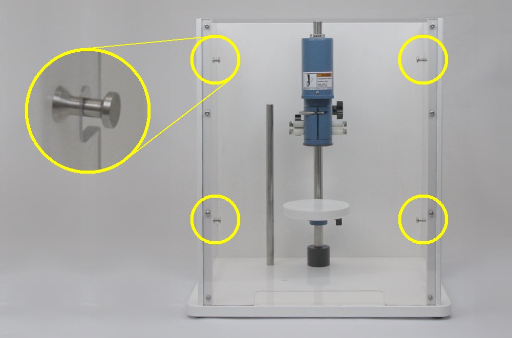
- Verify that the enclosure window is secured to all four pins as shown below.
- Vérifiez que l’arbre a été retiré du rotateur.
- Vérifiez que les vis hexagonales du raccord avec le moteur sont bien serrées.
- Vérifiez que les portes de la coque sont fermées et verrouillées.
- Vérifiez que les quatre broches de fermeture de la fenêtre du boîtier sont fermées tel qu’indiqué ci-dessous.
- Turn the rotation rate knob fully counter-clockwise. This is the position which corresponds to a nearly zero rotation rate.
- Reconnect the power cord and carefully switch on the rotator.
- Slowly turn the rotation rate control knob fully clockwise to the fastest rotation rate.
- The rotation rate display on the front panel of the control unit should read approximately
.
- Adjust trimmer P4 until the rotation rate display on the front panel of the control unit reads
- Turn the rotation rate knob fully counter-clockwise. This is the position which corresponds to a nearly zero rotation rate.
- The rotation rate display on the front panel of the control unit should read approximately
- Switch off power to the rotator and disconnect the power cord. While the power cord is disconnected, replace the cover on the control unit.
- At this point the calibration procedure is complete. Make a note in a log book or place a sticker on the control unit to record the calibration date.
Laser radiation.
Many optical tachometers use a laser beam as a light source.
Do not look directly at the laser beam. Do not point the laser beam into the eye.
AVERTISSEMENT:
Rayonnement laser.
Un grand nombre de tachymètres optiques utilisent un faisceau laser comme source de lumière. Ne regardez pas directement le faisceau laser. Ne pointez pas le faisceau laser dans l’oeil.
Rotating shaft. Very high rotation rates!
The next part of the calibration procedure involves rotation rates at or above .
Before continuing, verify each of the following points:
AVERTISSEMENT:
Arbre en rotation. Vitesses de rotation extrêmement élevées!
La prochaine partie de la procédure d’étalonnage implique des vitesses de rotation supérieures ou égales à .
Avant de continuer, vérifiez chacun des points suivants:
6.6.2 Sample Calibration Certificate
A blank calibration certificate can be found at the link below. Each time the rotator is (re)calibrated, it is a good idea to record the results of the calibration procedure on this form and then keep a copy of this form in a log book near the instrument.
6.7 Changing the Input Rotation Rate Ratio
The rotation rate can be controlled by applying an external voltage signal to the input jacks on the front panel of the control unit. The proportionality ratio used to convert the applied voltage signal to the rotation rate can be set to one of three different values: .
Normally, the value for the rotation rate ratio is selected to match the control signal provided by a particular potentiostat. When shipped from the factory, the MSR rotator is pre-configured with a ratio of because this ratio is compatible with Pine potentiostat systems.
CAUTION:
Static electricity may damage electronic components.
Ensure proper grounding when handling static sensitive components by wearing a grounding strap.
ATTENTION:
L’électricité statique est susceptible d’endommager les composants électriques.
Veillez à disposer d’une mise à la terre appropriée lorsque vous manipulez des composants sensibles en portant un ruban de mise à la terre.
- With the power cord disconnected, remove the cover from the control unit.
- Loosen the screw that secures the main analog board to the front panel, and then carefully remove the analog board.
- On the board, locate the configuration pins with the designation JP2. There is a small jumper that can be used to short together one of three pairs of pins.
- Place the jumper across one of the three pairs of pins at JP2.
- Choose the ratio required for the particular potentiostat being used with the rotator.
- Reinstall the board in the control unit and secure the board to the front panel.
- Replace the cover on the control unit.
- At this point the input ratio has been changed. Make a note in a log book or place a sticker on the control unit to indicate the new input ratio.
(Note: MSR rotator factory setting is )
6.8 Changing the Motor Stop Signal Logic
The motor stop signal on the back panel of the control unit is a digital signal that can be used to bring the motor to a complete stop. This digital signal can be configured for either “active high” or “active low” logic.
The motor stop signal usually originates from a potentiostat that is controlling the rotator. A cable from the potentiostat applies the signal to the Motor Stop banana jack (blue) on the back panel. This signal is a TTL-type digital logic signal with a voltage level that is measured versus the DC Common (i.e., any of the black banana jacks on either the front or back panel).
If the motor stop signal logic is configured for “active HIGH” logic, the behavior is as follows: The motor is allowed to rotate if a signal greater than is applied to the blue Motor Stop banana jack. The motor is stopped if the Motor Stop signal is driven to DC Common (i.e., it stops if the blue Motor Stop banana jack is shorted to any of the black DC Common jacks).
If the motor stop signal logic is configured for “active LOW” logic, the behavior is as follows: The motor is stopped if a signal greater than is applied to the blue Motor Stop banana jack. The motor is allowed to rotate if the Motor Stop signal is driven to DC Common (i.e., it rotates if the blue Motor Stop banana jack is shorted to any of the black DC Common jacks).
Normally, the choice for the Motor Stop signal logic is selected to match the control signal provided by a particular potentiostat. When shipped from the factory, the MSR rotator is pre-configured with “active HIGH” logic because this logic is compatible with Pine potentiostat systems.
CAUTION:
Static electricity may damage electronic components.
Ensure proper grounding when handling static sensitive components by wearing a grounding strap.
ATTENTION:
L’électricité statique est susceptible d’endommager les composants électriques.
Veillez à disposer d’une mise à la terre appropriée lorsque vous manipulez des composants sensibles en portant un ruban de mise à la terre.
- With the power cord disconnected, remove the cover from the control unit.
- Loosen the screw that secures the main analog board to the front panel, and then carefully remove the analog board.
- On the board, locate the configuration pins with the designation JP1. There is a small jumper that can be placed in one of two positions at this location.
- Place the jumper across one of the two positions shown below.
- Choose the position required for the particular potentiostat being used with the rotator.
- Reinstall the board in the control unit and secure the board to the front panel.
- Replace the cover on the control unit.
- At this point the motor stop signal logic has been changed. Make a note in a log book or place a sticker on the control unit to indicate the new logic.
Active LOW Position (AL) – Active HIGH Position (AH)
WaveNow Documents
This page contains useful links to documentation for the WaveNow USB Potentiostat offered by Pine Research Instrumentation.
- WaveNow Potentiostat Support Page.
- Document Index
- Document ID: LMTPCWUSB (Guide to Using Certified Wireless USB with the WaveNow & WaveNano Potentiostats)
MSR Rotator: User Description
 This article is adapted from Section 2 of the User Manual for the Pine Modulated Speed Rotator (MSR).
Related Links: MSR User Manual, MSR Rotator Support Page, Pine Research Instrumentation
Table of Contents
Section 2 – Description
The MSR rotator provides excellent steady-state control of constant rotation rates, but it also offers outstanding acceleration/deceleration control for those applications where the rotation rate must be modulated. The base rotation rate (for steady-state constant rate control) may be manually adjusted from to
by turning a ten-turn potentiometer knob located on the front panel of the control unit. As the knob is turned, a built-in tachometer measures the actual rotation rate, and this rate is continuously displayed on the front panel of the control unit. Manually turning the knob and observing the rotation rate is by far the most common manner in which the rotation rate is selected.
More complex control of the rotation rate is possible when the MSR rotator is connected to a potentiostat system capable of supplying an analog rotation rate signal. While specific details vary from one system to another, the basic idea is that the potentiostat produces an analog signal that is proportional to the target rotation rate. This analog signal is carried by a cable (supplied by the potentiostat manufacturer) to a pair of input banana jacks on the front panel of the rotator’s control unit. This connection permits the software which controls the potentiostat to control the rotation rate using a constant voltage level (for steady-state rotation) or a more complex waveform such as a sine wave (for hydrodynamically modulated voltammetry).
The rotator is able to accurately follow complex waveforms and create the desired rotation rate response by using a high rate, low inertia, permanent magnet DC motor in combination with a high voltage, bi-polar power supply. In general, the MSR can track and follow low frequency (less than ) external input signals with amplitudes that do not exceed
of the baseline rotation rate. The usual proportionality between the external input signal and the rotation rate is
, but a hardware jumper setting inside the control unit may be used to select the different ratios (see Section 6.7).
The rotation rate is typically monitored by observing the front panel display on the control unit. In addition, the tachometer measurement can be monitored by connecting an oscilloscope, voltmeter, or other recording device across the two output banana jacks on the front panel. The voltage signal from the tachometer presented at these output jacks is proportional to the rotation rate. The ratio used for this signal is .
The control unit is connected to the motor unit using a 15-conductor cable with “straight thru” wiring terminated on each end with HD-15 connectors.The usual cable length is (
), but longer distances can be spanned by chaining together multiple cables.
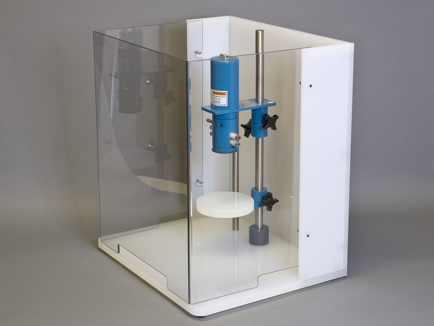
The motor unit can be positioned vertically along a center post that is mounted in a sturdy and chemically resistant enclosure base. A flat cell platform can also be positioned along the center post, making it easy to raise and lower the cell with respect to the motor unit. The electrochemical cell can be further secured by clamping it to a side post located adjacent to the center post.
Rotating shaft.
Do not turn on the rotator or rotate the electrode shaft unless the enclosure window is secured to all four pins as shown below.
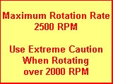
Use extreme caution when operating the rotator at rotation rates above
AVERTISSEMENT:
Arbre en rotation.
Ne mettez pas le rotateur en marche et ne marche ni l’arbre de l’électrode en rotation si la fenêtre du boîtier n’est pas fermée à l’aide des quatre broches tel qu’indiqué ci-dessous.
Soyez extrêmement prudent lorsque vous utilisez le rotateur à des vitesses de rotation supérieures à .
The motor unit and electrochemical cell are enclosed on the back side by a rear wall permanently attached to the enclosure base. The cell and motor are further enclosed on the front side by a transparent enclosure window. The enclosure window can be removed to set up the cell, but the enclosure window must be securely mounted to the enclosure base before rotating the electrode.
The rotator may be used with rotating disk electrodes (RDEs), rotating ring-disk electrodes (RRDEs), and rotating cylinder electrodes (RCEs). Connections to the rotating electrode shaft are made by two pairs of silver-carbon brushes. For RDEs and RCEs, all four brushes make contact with the rotating shaft and may be shorted together to obtain four points of contact. For RRDEs, the upper brush pair contacts the disk electrode, and the lower pair contacts the ring electrode.
2.1 Major System Components
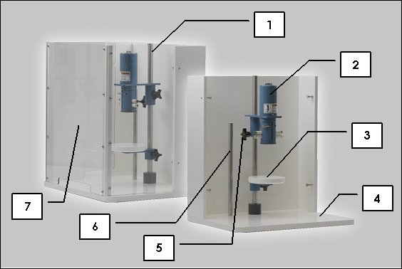
The table and photo below (see Figure 2.1) show the major system components.
1. Center Post – The cell platform, support collar, and motor unit are supported by the center post.
2. Motor Unit – The motor unit is mounted on the center post and holds the motor and brushes.
3. Cell Platform – The cell platform supports cells with flat bottom surfaces.
4. Enclosure Base – The support frame is fabricated from a chemically-resistant polymer.
5. Support Collar – The support collar helps prevent motor from unexpectedly sliding down center post.
6. Side Post – The side post is a support for cell clamps and can be installed in one of two positions.
7. Enclosure Window – This is a transparent window covering the front of the overall enclosure.
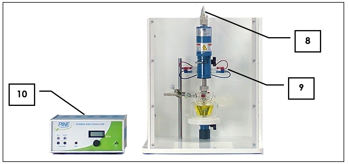
8. Motor Control Cable – This cable connects the control unit to the motor unit.
9. Banana Cables (red and blue) – The upper pair of brush contacts (red) is used with rotating disk electrodes (RDE) and rotating cylinder electrodes (RCE). The lower pair of brush contacts (blue) is only used with rotating ring-disk electrodes (RRDE), in which case the lower pair of brushes contact the ring while the upper pair of brushes contact the disk.
10. Control Unit – The control unit contains the power supply and rotation rate control circuitry.
2.2 Enclosure Variations
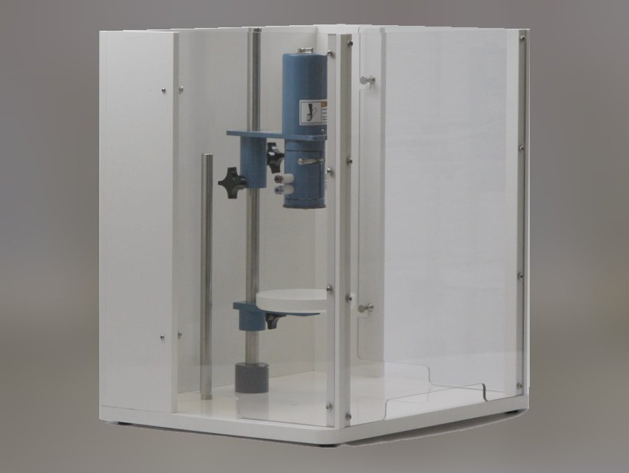
The enclosure consists of the enclosure base (fabricated from an opaque white polymer) and an enclosure window (transparent). The enclosure window may be a single pane (see Figure 2.2, left) or it may be assembled from three separate panes (see Figure 2.2, right).
Figure 2.2: Two Styles of Enclosure Window
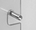
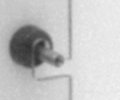
There are four hooks on the enclosure window which are secured to four anchor pins on the enclosure base. There are three styles of anchor pins.
Figure 2.3: Three Styles of Anchor Pins
The anchor pins may be simple straight pins (see Figure 2.3, left), or they may combine a pin with a rubber bumper (see Figure 2.3, middle), or they may be tapered pins (see Figure 2.3, right).
2.3 Control Unit Components
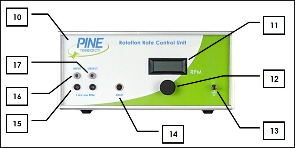
The tables and photos below (see Figure 2.4) show the control unit components.
10. Control Unit – The control unit contains the power supply and rotation rate control circuitry.
11. Rotation Rate Display – 4 ½ digit display of rotation rate ()
12. Rotation Rate Knob – 10 turn knob for manual rotation rate control
13.  Earth Ground – This connection to the control unit chassis and the motor unit chassis (via the motor control cable) is also connected to earth ground via the power cable “third prong”.
14. Reset Button – Motor circuit breaker reset
15. Signal Ground – DC signal common (isolated from chassis)
16. Rotation Rate Input Signal – External control of the rotation rate is possible by applying a voltage signal across these banana jacks (see Section 4.7.3). (, or
ratio,
impedance)
17. Rotation Rate Output Signal – A voltage signal proportional to the rotation rate is presented at these banana jacks. (,
output impedance)
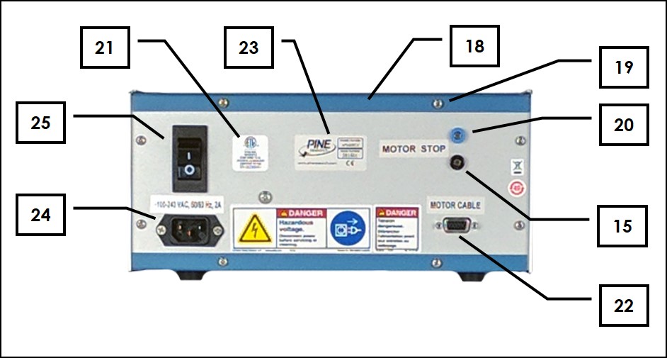
18. Control Box Cover – Metal cover
19. Control Box Cover Screws – Metal screws that hold cover on control unit
20. Motor Stop Input Signal – This digital logic signal is used to stop electrode rotation (see Section 4.6.4).
21. NRTL Mark – Nationally Recognized Testing Laboratory compliance label (ETL Mark from Intertek)
22. Motor Cable Connector – Accepts one end of motor control cable
23. Serial Number Plate – Unique system serial number
24. Power Cord Connector – Connects to external electrical power cord
25. Power Switch – Main power switch (with circuit breaker)
2.4 Motor Unit Components
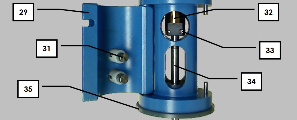
The table below and the photographs (see Figure 2.5) identify the major components of the motor unit.
26. Motor Cable Connector – Accepts one end of motor control cable
27. Upper Brush Pair (red) – These upper brushes make contact on opposing sides of the rotating shaft and are used to make contact with rotating disk electrodes and rotating cylinder electrodes.
28. Lower Brush Pair (blue) – These lower brushes make contact on opposing sides of the rotating shaft and are used to make contact with the ring electrode when working with rotating ring-disk electrodes.
29. Clamshell Doors – These doors open to permit access to the brush chamber
30. Door Latch – Secures clamshell doors in closed position
31. Brush Contact – Spring-loaded silver-carbon brush provides electrical contact with the rotating shaft
32. Motor Coupling – Used to attach the shaft to the motor
33. Motor Coupling Hex Screw Pair – Hex screws located on either side of the motor coupling tighten to hold the shaft inside the motor coupling
34. Electrode Shaft – The top end of the rotating shaft is mounted in motor coupling and the active electrode surface is at the bottom end of the shaft.
35. Lower Bearing Assembly – An easily replaceable bearing assembly stabilizes the rotating shaft at the point where the shaft exits the motor unit. Metal and ceramic bearings are available.
2.5 Typical Rotating Disk Electrode Design
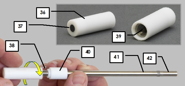
Most rotating disk electrodes consist of two parts (see Figure 2.6), a shaft and a tip, but in some cases the entire electrode may be a single piece.
36. Insulating Shroud on Tip – This insulating shroud material is typically a polymer such as PTFE, PEEK or PCTFE.
37. Electrode Surface – The electrode surface is typically polished to mirror smoothness.
38. Threads on shaft – These threads are normally in electrical contact with disk.
39. Threads inside tip – These threads are normally in electrical contact with disk.
40. Insulating Shroud on Shaft – This insulating shroud material is typically a polymer such as PTFE, PEEK or PCTFE.
41. Disk Contact Area – This metal area on the shaft is normally in electrical contact with disk.
42. Shaft Mounting Area – This electrically-isolated portion of the shaft is used to physically mount the shaft in the motor coupling.
2.6 Typical Rotating Ring-Disk Electrode Design
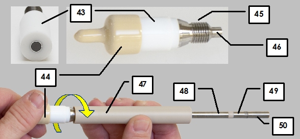
Rotating ring-disk electrode tips mount on to a special two-conductor shaft (see Figure 2.7). In some cases, the tip can be taken apart into smaller pieces.
43. Insulating Shroud on Tip – This insulating shroud material is typically a polymer such as PTFE, PEEK or PCTFE.
44. Plastic Cover – Cover protects electrode when not in use.
45. Ring Threads on Tip – These threads contact the ring electrode.
46. Disk Core on Tip – This disk core is in electrical contact with the surface of the disk electrode.
47. Insulating Shroud on Shaft – This insulating shroud material is typically a polymer such as PTFE, PEEK or PCTFE.
48. Ring Contact Area – This metal area on the shaft is normally in electrical contact with the ring electrode.
49. Disk Contact Area – This metal area on the shaft is normally in electrical contact with the disk electrode.
50. Shaft Mounting Area – This electrically-isolated portion of the shaft is used to physically mount the shaft in the motor coupling.
Taking Care of Your E3 Series Rotating Disk Electrode
-
Your rotating disk electrode (RDE) is a precision research tool that has been carefully machined and tested. It is guaranteed to be leak-free at the time of shipment.
-
Your electrode was leak tested at ambient temperature and should not be used at elevated temperatures. The electrode should only be used at temperatures from
(
) to
(
). Higher temperatures may create a leak between the shroud and the electrode material.
-
After using the electrode, clean it and replace the protective cover to prevent the electrode surface from being scratched.
-
Rotating electrodes must be mounted securely in the rotator. While mounting, do not apply excessive force to the PTFE shroud as this may cause the shroud to slip along the shaft of the electrode.
-
Rotating electrodes should be submerged at least
(
) below the surface of the solution.
-
Rotating electrodes should be mounted in such a way that they do not rub against surfaces (such as the inner wall of the cell).
Using an E3 Series RDE Tip with an MSR Rotator
-
Use shaft AFE3M when attaching an E3 Series RDE tip to an MSR rotator.
-
A line drawing showing the AFE3M shaft and an E3 Series RDE tip is provided below. Note that approximate dimensions are given in millimeters.
-
When properly mounted in an MSR rotator, the first
of the AFE3M shaft are inserted up inside the rotator. The remaining portion of the shaft extends down below the rotator.
Using Certified Wireless USB with Pine Potentiostats
Document ID: LMTPCWUSB (REV 1) 17-FEB-2009

This document describes how to use a certified wireless USB hub in conjunction with the WaveNow and WaveNano USB Potentiostats offered by Pine Research Instrumentation. Note that the Certified Wireless USB protocol is one of several competing types of wireless USB protocols. Devices which use Certified Wireless USB are usually marked with the logo shown to the right.
Introduction
Pine offers a Certified Wireless USB kit for use with the Pine WaveNow and WaveNano potentiostats. This kit contains a four-port hub, a power cord, a standard USB cable, and a CD-ROM used to install required device drivers on your computer.
It is absolutely necessary to install the software and hardware in the sequence described by the original manufacturer.
Installation Instructions
The four main steps are:
-
1. Insert the CD and install the software
-
2. Connect the powered-on wireless hub to the computer using the supplied special cable
-
3. Disconnect the wireless hub from the computer after the “association” process is complete (detailed description and screenshots in manufacturer's directions)
-
4. Connect the wireless adapter
Follow the instructions provided by the original manufacturer when installing the device driver software and hardware on your computer. These instructions can be found in both the original manufacturer's “Quick Installation Guide” (shipped with the product inside the manufacturer's packaging) and also at the link shown below:
Performance Expectations
The manufacturer claims a wireless range of “up to” 30 feet. In our experience, 10 to 20 feet of unobstructed, line-of-sight range should be expected. The performance also seems to be negatively affected by movement, including movement of the wireless hub, the wireless adapter, and people/animals within the room (walking between the hub and adapter).
Part Numbers
This Certified Wireless USB Kit for WaveNow and WaveNano Potentiostats was given Pine Research Part #: AKWUSB.
WaveNow & WaveNano Potentiostats: Read This First
Document ID: LMTPFIRST (REV 1) 03-APR-2009
This document provides links to important information about how to set up your WaveNow or WaveNano USB Potentiostat.
Documentation
All documentation for your potentiostat and the AfterMath software package can be found at our on-line “knowledgebase” site. There are several very useful entry points to our knowledgebase site listed below:
Cell Connections
Both the WaveNow and WaveNano have connections for a working electrode DRIVE signal and a working electrode SENSE signal. For conventional “three-electrode” voltammetry, the DRIVE and SENSE lines must be shorted together at a point near the electrochemical cell (see link below for more information):
Software Updates
From time to time, Pine will post updates to the AfterMath software.
Additional Support
As always, if you need any help with any Pine product, please feel free to give us a call or contact us via e-mail.
WaveDriver 20 Bipotentiostat: Read This First
Document ID: LMWD20FIRST (REV 002) 12-OCT-2012
This document provides links to important information about how to set up your WaveDriver 10 Potentiostat or WaveDriver 20 Bipotentiostat.
Documentation
All documentation for your potentiostat and the AfterMath software package can be found at our on-line “wiki” site. There are several very useful entry points to our wiki site listed below:
Cell Connections
The WaveDriver potentiostats have separate connections for working electrode DRIVE signals and a working electrode SENSE signals. For conventional “three-electrode” voltammetry, the DRIVE and SENSE lines must be shorted together at a point near the electrochemical cell (see links below for more information):
Software Updates
From time to time, Pine will post updates to the AfterMath software.
Additional Support
As always, if you need any help with any Pine product, please feel free to give us a call or contact us via e-mail.
Pine Research Instrumentation Electrode Documentation
This page contains useful links to documentation for many of the electrode offered by Pine Research Instrumentation. Some of these documents are maintained on Pine's commercial web site, while others are maintained in whole or in part on this website.
Screen-Printed Electrodes
Rotating Disk Electrodes (RDE)
Rotating Ring-Disk Electrodes (RRDE)
Rotating Cylinder Electrodes (RCE)
Traditional 3-Electrode Voltammetry
Device Driver for Avantes AvaSpec Spectrometers
USB Device Driver
A USB device driver must be installed on Microsoft Windows computers in order to use Avantes AvaSpec spectrometers. This device driver software is a product supplied by Avantes BV.
As of February 2015, the supported version of the device driver is available for download as an executable file.
Installation Instructions
Download and run the executable file for the driver installation. It may be necessary to choose the “Run as Administrator…” option when you attempt to execute the driver installer.
Activation
To activate the device driver, your Windows system must “discover” the new instrument connected to your system.
As with most USB-connected devices, this discovery occurs when you turn on and connect the device to your system via a USB cable. The device driver should be installed BEFORE connecting the device, and the device should be connected BEFORE running Aftermath. If the driver installation was successful, then the instrument should appear in the instrument list in the lower-left corner of the AfterMath screen.
Additional Resources
Related Software Links: AfterMath Support Page, AfterMath User Guide, AfterMath Electrochemistry Guide, AfterMath Installation Guide
AfterMath Viewer

This article is part of the AfterMath Data Organizer User’s Guide
AfterMath Viewer can be used to see (and print) experiment results that have been previously collected by full versions of our AfterMath software.
AfterMath Viewer is also able to import data files obtained using our classic PineChem software for the Pine AFCBP1 bipotentiostat.
Click here for comparison of AfterMath to the older PineChem software.
Click here to get the latest AfterMath version with:
-
No device drivers
-
No experiment techniques


