


This article is part of the Pine WaveNow USB Potentiostat User's Guide
Cable Kit Description
The most generic cell cable kit available for the WaveNow Potentiostat (part number AKCABLE3) provides four signal lines which terminate in banana plugs and/or female BNC connectors. This kit also comes with alligator clips that slide on to the banana plugs. This cable kit uses the standard PRI electrode color scheme used on all Pine products since the year 2007.


One one end of the cable is a sturdy male HD-15 connector which mates with the cell port on the side of the WaveNow potentiostat. Four separate signal lines emerge from this connector; two of these lines are coaxial cables, and the other two are banana cables which terminate with stackable banana plugs.
The signals carried in the banana cables drive current through the cell. The RED banana cable should be connected to the working electrode, and the GREEN banana cable should be connected to the counter electrode. The main current path through the electrochemical cell is between the working electrode and counter electrode, so most of the current flowing through the cell will travel through the RED and GREEN banana cables.
The signals carried in the two coaxial lines are sensitive high-impedance measurements of cell potentials. Very little current flows through these signal lines. The coaxial line marked with the WHITE band is connected to the reference electrode so that the potentiostat can carefully measure the reference electrode potential.
The other coaxial line, marked with an ORANGE (or sometimes red) band is the working electrode sense line. The potentiostat uses this signal line to carefully measure the potential of the working electrode. This should be connected to the working electrode at a point very near the electrochemical cell.
Tip: Working Electrode Sense Connection
The easiest way to connect the working electrode sense line at a point near the electrochemical cell is to simply insert the orange banana plug into the back end of the red (stackable) banana plug. Then, make the connection to the working electrode using an alligator clip on the red banana plug (see below).

If you are using the WaveNow potentiostat with a Pine rotating disk electrode, insert the red banana plug into the the disk electrode jack first. Then, insert the orange banana plug into the back end of the red banana plug.
Tip: Reference Electrode Connection
If you are using a reference electrode with a “pin” connector, then simply slide an alligator clip on to the white banana plug and use the clip to attach to the pin connector.
Some reference electrodes sold by Pine already have a long coaxial cable with a male BNC plug at the end of the cable. This kind of reference electrode can be connected to the Universal Cell Cable by taking apart the cable apart at the BNC junction as shown in the photo below. After taking apart the cable, there is a female BNC connector to which can mate with the reference electrode's male BNC connector.

Ordering Information
AKCABLE3 can be purchased from Pine Research Instrumentation at the provided link
Part numbers for various items in this kit are provided in the table below.
Part Number
AKCABLE3
RRTPE10
RRTPE11
RRTPE12
THCLIP
Description
This is the complete cable kit
This is the main portion of the cable which breaks out of the HD-15 connector
This is the coax cable terminating at a white banana plug (for reference electrode)
This is the coax cable terminating at an orange banana plug (working electrode sense)
This is the alligator clip that slides on to a banana plug
Read More
WaveNow: AKCABLE5
This article is part of the Pine WaveNow USB Potentiostat User's Guide
Cable Kit Description
This kit (Pine part number AKCABLE5) provides a generic cell cable which is compatible with the WaveNow and WaveNano potentiostats.
The WaveNow and WaveNano potentiostats feature an HD-15 cell connection port located on the side of the potentiostat. This port presents several signal, shield, and grounding lines for the working, counter, and reference electrode connections.
The Shielded Cell Cable kit breaks out the various cell port lines to shielded coaxial cables which terminate at stacked banana plugs. This kit also comes with alligator clips that slide on to the banana plugs. The banana plugs are color coded according to the standard PRI electrode color scheme used on all Pine products since the year 2007.


WaveNow/WaveNano Shielded Cell Cable Kit (part number AKCABLE5)
Current is driven through the electrochemical cell between the working electrode and the counter electrode. A pair of signal lines are used to drive charge between these electrodes. The working electrode drive line (working) is the coaxial cable which terminates at a RED banana plug. The counter electrode drive line (counter) is the coaxial cable which terminates at a GREEN banana plug. Because the primary current path through an electrochemical cell is between the working electrode and counter electrode, most of the charge flowing through the cell will travel through these two cables.
Potentials in the electrochemical cell are sensed using signal lines with high input impedance. Very little charge flows through these high impedance signal lines. The potential difference between the working electrode and the reference electrode is measured using a pair of high impedance sense lines. The working electrode sense line (working sense) is the coaxial cable which terminates at an ORANGE banana plug. The reference electrode sense (reference) line is the coaxial cable which terminates at the WHITE banana plug.
A separate signal ground line which terminates at a BLACK banana plug is also provided. This ground line should be connected to any Faraday cage that might be in use to shield the electrochemical cell from electromagnetic noise sources. If you are using a rotating electrode, it is a good idea to connect this ground line to the metal body of the rotator.
Color Code
GREEN
WHITE
RED
ORANGE
BLACK
Description
Counter Electrode
Reference Electrode
Working Electrode (drive line)
Working Electrode (sense line)
DC Common (signal ground)
Tip: Working Electrode Sense Connection
The working sense signal should be shorted together with the working drive line at a point very near the electrochemical cell. This is usually accomplished by stacking the ORANGE banana cable with the RED banana cable. Alternately, you may clip the alligator clip of the working sense line (ORANGE) to the alligator clip on the working drive line (RED).


Short the Working Sense to the Working Electrode
If you are using this cable kit to make connections to a Pine rotating electrode, you may connect the working drive line (RED banana plug) to one of the disk pickup brushes and then connect the working sense line (ORANGE banana plug) to the opposite disk pickup brush.
Tip: Reference Electrode Connection
If you are using a reference electrode with a “pin” connector, then simply slide an alligator clip on to the WHITE banana plug and use the clip to attach to the pin connector.

Connect Alligator Clip to Reference Electrode Pin
Ordering Information
Part numbers for various items in this kit are provided in the table below.
Part Number
AKCABLE5
RRTPE30
THCLIP
Description
This is the complete cable kit
This is the main cable which breaks the HD-15 connector out to the banana plugs
This is the alligator clip that slides on to a banana plug
AKCABLE5 can be purchased from Pine Research Instrumentation at the provided link
Read More

WaveDriver Potentiostat: Limited Warranty
PINE RESEARCH INSTRUMENTATION
LIMITED WARRANTY
The WaveDriver 10 or WaveDriver 20 Potentiostat (hereafter referred to as the “INSTRUMENT”) offered by Pine Research Instrumentation (hereafter referred to as “PINE”) is warranted to be free from defects in material and workmanship for a one (1) year period from the date of shipment to the original purchaser (hereafter referred to as the “CUSTOMER”) and used under normal conditions. The obligation under this warranty is limited to replacing or repairing parts which shall upon examination by PINE personnel disclose to PINE's satisfaction to have been defective. The customer may be obligated to assist PINE personnel in servicing the INSTRUMENT. PINE will provide telephone support to guide the CUSTOMER to diagnose and effect any needed repairs. In the event that telephone support is unsuccessful in resolving the defect, PINE may recommend that the INSTRUMENT be returned to PINE for repair.
This warranty being expressly in lieu of all other warranties, expressed or implied and all other liabilities.
All specifications are subject to change without notice.
The CUSTOMER is responsible for charges associated with non-warranted repairs. This obligation includes but is not limited to travel expenses, labor, parts and freight charges.
WaveNow Quickstart: Cables

Note: This is one of many articles describing how to use the Pine WaveNow USB Potentiostat
WaveDriver Potentiostat: Limited User Warranty
This article is part of the Pine WaveDriver Potentiostat User's Guide
PINE RESEARCH INSTRUMENTATION
LIMITED WARRANTY
The WaveDriver 10 or WaveDriver 20 Potentiostat (hereafter referred to as the “INSTRUMENT”) offered by Pine Research Instrumentation (hereafter referred to as “PINE”) is warranted to be free from defects in material and workmanship for a one (1) year period from the date of shipment to the original purchaser (hereafter referred to as the “CUSTOMER”) and used under normal conditions. The obligation under this warranty is limited to replacing or repairing parts which shall upon examination by PINE personnel disclose to PINE's satisfaction to have been defective. The customer may be obligated to assist PINE personnel in servicing the INSTRUMENT. PINE will provide telephone support to guide the CUSTOMER to diagnose and effect any needed repairs. In the event that telephone support is unsuccessful in resolving the defect, PINE may recommend that the INSTRUMENT be returned to PINE for repair.
This warranty being expressly in lieu of all other warranties, expressed or implied and all other liabilities.
All specifications are subject to change without notice.
The CUSTOMER is responsible for charges associated with non-warranted repairs. This obligation includes but is not limited to travel expenses, labor, parts and freight charges.
WaveDriver Potentiostat: QuickStart Guide
This article describes a very fast way to test your WaveDriver potentiostat system. By connecting the potentiostat to a well behaved network of resistors and capacitors (known as a “Dummy Cell”), the potentiostat circuitry can be tested to assure that it is working properly.
Cyclic Voltammetry
This section describes how to set up AfterMath and the WaveDriver to perform cyclic voltammetry. Step-by-step instructions are provided below.
Step 1
Login to the AfterMath software (which you should have previously installed on your computer).
Installation instructions may be found here.

Step 2
Connect the WaveDriver Potentiostat to your computer using a USB cable.

Step 3
Connect the power supply to the potentiostat and then connect the power supply to power source (wall outlet) using an appropriate power cord. Note that Pine offers a variety of international power cords for use around the world, and the power supply is compatible with power sources ranging from 100 to 240 VAC (50 or 60 Hz).


Step 4
Turn on the potentiostat using the front panel power switch and wait for the WaveDriver to appear in the AfterMath Instrument List (see below).

Step 5
Check the status light on the WaveDriver Potentiostat. It should be green, indicating that the potentiostat is idle. The USB indicator light should flicker occasionally.

Step 6
Connect one end of the cell cable to the front panel of the WaveDriver. Connect the other end to the universal dummy cell (use cell “B” as shown below). Connect the black banana plug on the cell cable to the chassis ground connector on the dummy cell. Connect all of the other banana plugs to the banana jacks with corresponding colors on the dummy cell. Note that the BLUE and VIOLET banana plugs are only found on the WaveDriver 20 Bipotentiostat cell cable. The WaveDriver 10 Potentiostat does not have the BLUE and VIOLET banana plugs.

Step 7
Examine the Instrument Status (see below). Initially, the status should indicate that the cell is in a “disconnected” state. If desired, you may use the controls to apply a known idle condition to the cell. In the example below, the instrument has been adjusted to idle in the potentiostat mode while applying +1.2 volts to the working electrode.

Step 8
Starting from the AfterMath Experiments menu, navigate to the Dual electrode methods sub-menu and select the Dual Electrode Cyclic Voltammetry (DECV) option from the experiment list. A new DECV experiment specification is created and placed in a new archive (see below). To configure the parameters properly, (1) first click on the “I Feel Lucky” button, then change the current ranges, (2) and (3), to the 1.0 mA range, and finally, (4) change the mode to “Window”.

Step 9
Select the Advanced tab. Set the Threshold to “None” under Sampling. If your version of AfterMath does not offer “None” as an option, enter zero.
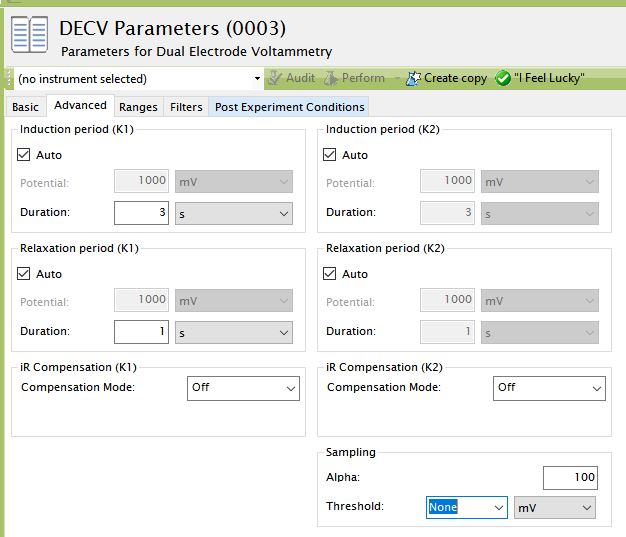
After setting threshold, return to the Basic tab.
Step 10
Choose the WaveDriver potentiostat in the drop-down menu (to the left of the “Audit” button). Then, press the “Perform” button to start the experiment.

Step 11
Monitor the progress of the experiment on the real time plot or the progress bar.

Step 12
When the experiment is finished, the results of the experiment are placed in a study folder in the archive. In addition to the main plot of the voltammogram, additional graphs are created in the “Other Plots” folder. The results are also available in tabular form.

![]() Note:
Note:
The diagonal traces in the plot above are not actual voltammograms. This slope of these traces represent the expected result for the resistance in the dummy cell circuit.
Using Your Own Electrochemical Cell
When you are ready to connect the cell cable to your own electrochemical cell, it is important to understand the signals associated with each of the seven banana plugs on the cell cable. Consult the following documentation describing the cell cable and how to connect the cell cable to various types of electrochemical cells:
![]() IMPORTANT NOTE:
IMPORTANT NOTE:
The WaveDriver working electrode connections feature separate working electrode DRIVE and SENSE lines. The SENSE and DRIVE lines are normally shorted together at a point near the electrochemical cell. This connection is quite easily accomplished by pushing the SENSE line banana plug into the back of the DRIVE line banana plug. Failure to short the DRIVE and SENSE lines together makes the potentiostat unstable and produces invalid results.
Additional Resources
Related Software Links: AfterMath Support Page, AfterMath User Guide, AfterMath Electrochemistry Guide, AfterMath Installation Guide
Related Hardware Links: WaveDriver 10 Potentiostat, WaveDriver 20 Bipotentiostat
WaveDriver Potentiostat: System Specifications

The WaveDriver Potentiostat is a benchtop USB potentiostat capable of performing a wide range of electroanalytical techniques. It has a small footprint, fast and easy computer interface, and robust data control and data organizer software, AfterMath.
Electrode Connections
Part Name
Product Name
Cell Port
Reference Electrode
Counter Electrode
First Working Electrode
Second Working Electrode
AFP1
WaveDriver 10
combination coaxial DSUB connector (front panel)
sense line with driven shield
drive line
separate sense and drive lines, each with driven shield (current measurement via passive shunt)
separate sense and drive lines, each with driven shield (current measurement via passive shunt)
Grounding
Part Name
Product Name
Signal Ground
Instrument Chassis
AFP1
WaveDriver 10
isolated from USB port, floats with respect to instrument chassis
banana binding post connection (back panel)
Measured Current
Part Name
Product Name
Practical Range§
Ranges
Resolution (at each range)
Autoranging
Accuracy
Leakage Current
ADC Input
Filter
AFP1
WaveDriver 10
100 pA to 1.0 A
±1 A, ±100 mA, ±10 mA, ±1 mA, ±100 μA, ±10 μA, ±1 μA, ±100 nA
31.3 μA, 3.13 μA, 313 nA, 31.3 nA, 3.13 nA, 313 pA, 31.3 pA, 3.13 pA
Yes
± 0.2% setting; ±0.05% of range
10 pA at 25˚C
16 bits
10 Hz, 30 Hz, 100 Hz, 1 kHz, 10 kHz (2-pole, low pass Bessel filter)
Applied Current (galvanostat mode)
Part Name
Product Name
Ranges
Resolution (at each range)
Accuracy
ADC Input
AFP1
WaveDriver 10
±1 A, ±100 mA, ±10 mA, ±1 mA, ±100 μA, ±10 μA, ±1 μA, ±100 nA
31.3 μA, 3.13 μA, 313 nA, 31.3 nA, 3.13 nA, 313 pA, 31.3 pA, 3.13 pA
± 0.2% setting; ±0.05% of range
16 bits
Power Amplifier (counter electrode amplifier)
Part Name
Product Name
Output Current
Compliance Voltage
Speed
Bandwidth
Rise Time
AFP1
WaveDriver 10
±1.0 A (maximum)
> ±16.5 V
9 available speed settings
> 200 kHz (on fastest speed setting)
10 V/μsec (on fastest speed setting)
Electrometer (reference electrode amplifier)
Part Name
Product Name
Input Impedance
Input Current
CMRR
Bandwidth
AFP1
WaveDriver 10
>1013 Ω in parallel with < 10 pF<10 pA leakage/bias current at 25˚C
> 84 dB at 0 to 1 kHz; > 74 dB at 10 kHz
> 11 MHz (3 dB)
Applied Potential (potentiostat mode)
Part Name
Product Name
Ranges
Resolution (at each range)
Accuracy
DAC Output
CV Scan Rate (min)
CV Scan Rate (max)
AFP1
WaveDriver 10
±10.0 V, ±2.5 V
313 μV, 78 μV
± 0.2% setting, ± 1.0 mV
16 bits
10 μV/sec (313 μV per 31.3 sec or 78 μV per 7.8 sec)
125 V/sec (10 mV step per 80 μsec)
Measured Potential
Part Name
Product Name
Ranges
Resolution (at each range)
Accuracy
ADC Input
Filters
AFP1
WaveDriver 10
±10.0 V, ±2.5 V
313 μV, 78 μV
± 0.2% setting; ±0.05% of range
16 bits
10 Hz, 30 Hz, 100 Hz, 1 kHz, 10 kHz (2-pole, low pass Bessel filter)
Rotator Control Connections (back panel)
Part Name
Product Name
Connector A
Connector B
Rate Control Signal
Digital Enable Signal
AFP1
WaveDriver 10
7-pin mini circular DIN includes analog and digital signal grounds, digital rotator enable
signal, auxiliary digital output signal, and analog rotation rate control signal
3-pin connector includes analog signal ground, digital rotator enable signal, and analog
rotation rate control signal.
±10.0 V, ±2.5 V
open drain (TTL compatible)
Data Acquisition
Part Name
Product Name
Clock Resolution
Point Interval*
Synchronization
Raw Point Total
AFP1
WaveDriver 10
10 nsec (minimum time base)
80 μsec (minimum)
simultaneous sampling of all analog input signals
< 10 million per experiment
Accessories
Part Name
Product Name
Universal Dummy Cell
Cell Cable
AFP1
WaveDriver 10
external dummy cell (included)
combination DSVB connector to multiple banana plugs via shielded coaxial cables (included)
Auxiliary Connections (back panel)
Part Name
Product Name
Connector C
Trigger Input
Trigger Output
BNC female, TTL compatible
K1 Input, K2 Input
Auxiliary Analog Output
Auxiliary Analog Input
AFP1
WaveDriver 10
9-pin DSUB connector includes digital signal ground, two digital output signals, and
three digital input signals
BNC female, TTL compatible
BNC female, ±10 V differential input, 20 kΩ impedance, ±0.5% accuracy; allows external
waveform to be summed directly to the working electrode excitation signal
(K2 Input available only on WaveDriver 20 bipotentiostat)
BNC female, ±10 V bipolar output, 313 μV resolution, 0.2% accuracy
(available only when second working electrode not in use)
BNC female, ±10 V differential input, 313 μV resolution, 20 kΩ impedance,
0.2% accuracy (available only when second working electrode not in use)
General Specifications
Part Name
Product Name
Power Required
Power Adapter
Power Cable
LED Indicators
Instrument Dimensions
Instrument Weight
Shipping Dimensions
Shipping Weight
Temperature Range
Humidity Range
AFP1
WaveDriver 10
24.0 VDC (±5%), 4 A (low voltage DC device)
100 to 240 VAC, 2.3 A, 50 to 60 Hz
various international cables available separately (C13 type)
power, USB, and status
140 x 305 x 248 mm (5.5 x 12.0 x 9.75 in.)
3.6 kg (8 lb)
254 x 356 x 457 mm (10 x 14 x 18 in.)
7.7 kg (17 lb)
10˚C to 40˚C
80% RH Maximum, non-condensing
*Data acquisition using the minimum point interval is possible for short duration bursts. The burst duration depends upon the available host PC USB bandwidth and is typically at least 3 seconds.
§The “practical range” of measurable currents goes from the maximum current output of the amplifier down to the current level at which noise begins to interfere with the signal. Using proper grounding, a cell shielded by a Faraday cage and coaxial cell cables, it is possible to routinely measures signals as low as 100 pA.
WaveDriver Potentiostat: Universal Dummy Cell
This article is part of the Pine WaveDriver Potentiostat User's Guide
A universal “dummy cell” is available for use with any Pine potentiostat (see link below).
https://pineresearch.com/shop/products/accessories/universal-dummy-cell-aqueous/
Note that one universal dummy cell is included with the purchase of each WaveDriver potentiostat system.
Related Links: Electrochemist's Guide to AfterMath, AfterMath Support Site, WaveDriver Support Site
WaveDriver Potentiostat: Introduction
This article is part of the Pine WaveDriver Potentiostat User's Guide
Scope of this Guide
This User's Guide describes the basic functions of the WaveDriver 10 potentiostat/galvanostat and the WaveDriver 20 bipotentiostat/galvanostat systems, including product specifications and limitations, product warranty, proper electrical connections, and other technical information.
This guide deals primarily with initial installation of the WaveDriver system and proper connections from the potentiostat to an electrochemical cell. Because the WaveDriver is primarily controlled using software, it is important to read and understand the following guides pertaining to Pine's AfterMath Data Organizer software:
This guide is written for the professional scientist or engineer (or student of science and engineering) and assumes a basic knowledge of scientific measurement and data presentation. Portions of this manual devoted to electrochemical concepts assume some familiarity with the subject of electrochemistry.
WaveDriver Potentiostat: AfterMath Software
The WaveDriver User Guide has two sections describing the AfterMath software:
In addition, more information on how to run experiments in the AfterMath software can be found at the Quickstart Guide for the WaveDriver Potentiostat.
Related Links: Electrochemist's Guide to AfterMath, AfterMath Support Site, WaveDriver Support Site