
 Are you looking to purchase a new potentiostat for your research lab? Whether you’re a new faculty, veteran electrochemist, graduate student, or industrial chemist, finding the right potentiostat can be difficult. Understanding specifications such as potential and current range is reasonably straight forward, but what about compliance voltage, ADC inputs, input impedance, and CMRR? Are these important? How will you know the optimal potentiostat specifications for an experiment you’ve never performed? Rest assured. In this article, we hope to debunk some of these specifications and provide you with real information you need when deciding which potentiostat to purchase.
Before diving into the topic of potentiostat specifications, a brief mention on terminology. Without even referring to a potentiostat, electrochemistry itself is full of confusing jargon. In describing the usefulness of certain specifications, this article will use the phrase “voltage” and “potential.” A voltage refers to the difference between two electrodes, and we use the term “voltage” when describing energy storage devices like batteries and fuel cells. We will use the phrase “potential” when referring to an individual electrode, redox reaction, and traditional 3-electrode solution phase electrochemistry experiments.
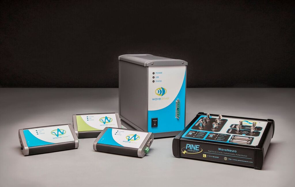
Regarding potentiostat terminology, the name “potentiostat” actually describes its function. “Potentio” refers to electrical potential, and “stat” stems from the Greek word “stato,” which means standing or set. Similarly, you use a “thermostat” to set the temperature in a room. You may recall from analytical chemistry or an instrumentation course that a potentiostat is made up of several operational amplifiers with the sole purpose of maintaining a controlled potential through feedback loops. However, performing electrochemical experiments require additional equipment. A potentiostat, waveform generator, and chart recorder were some of the items used by researchers when potentiostats were first developed. These early systems didn’t include controlled current techniques (galvanostat) or electrochemical impedance spectroscopy (EIS) and required separate circuitry. A modern potentiostat, by contrast, contains most of these components to form a single “out-of-the-box” instrument for electrochemistry experiments. Some potentiostats have multiple channels and are referred to as bi and multi-channel potentiostats. Another phrase that is tossed around is “electrochemical workstation” or “potentio/galvanostat system.” All of these terms make up what we call a “potentiostat” and they all refer to the same thing…a black box with a bunch of cables coming out of it that you hook up to your electrochemical system, and pray to the ghost of Michael Faraday that your experiment works.
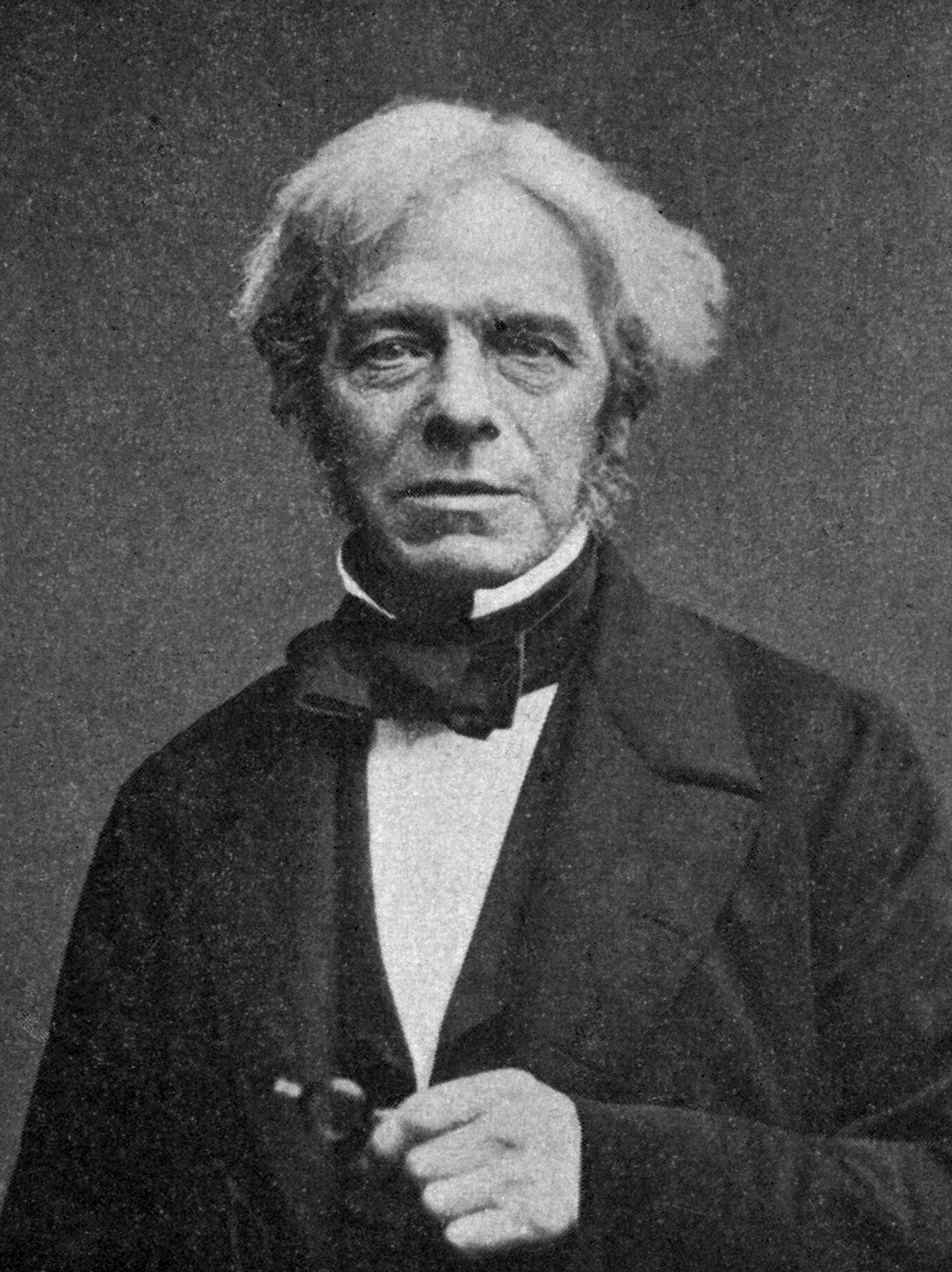
The Great Michael Faraday, we can only hope to aspire to his awesome electrochemistry skills – p. 290 of Millikan and Gale’s Practical Physics (1922), Public Domain, https://commons.wikimedia.org/w/index.php?curid=2525521
Now that the terminology is understood, let’s start with the most important question when choosing a potentiostat (or any analytical instrument for that matter). Will the instrument work for your application? In the world of scientific research, you never know if an experiment is going to work. Most of the time, it does not. You may feel comforted to know this is somewhat “par for the course,” particularly in the field of electrochemistry (Michael Faraday frowns upon us). However, an inadequate instrument should not be the reason why an experiment fails. When purchasing a potentiostat, you need to make sure that it has the capability to measure what you are trying to study. For example, if you are working in highly resistive solutions, your potentiostat needs a high compliance voltage to overcome the solution resistance. As you read this article, keep in mind the kind of data you will require of your potentiostat based on your experimental design.
What potential range do you need?
The potential range needed will depend on your application. For electrochemistry at a solid-liquid interface, we need to recognize differences between using aqueous and non-aqueous solvents. The electrolysis of water is your primary limiting factor when working in aqueous solvents. The potential window for water is roughly -1 to +1 V vs. the normal hydrogen electrode (NHE).1 This window can vary with supporting electrolyte, working electrode material, and pH, but as a ballpark estimate, your potentiostat does not likely need capabilities beyond -2 to +2 V vs. NHE for aqueous electrochemistry.
Non-aqueous solutions, on the other hand, carry a much wider potential range. For example, acetonitrile has a potential window between -2.5 to +2.5 V vs. NHE.1 Regarding non-aqueous solvents, there two things to note.
- The potential range of the solvent is highly dependent on contamination. Techniques such as cyclic voltammetry are very sensitive to trace contaminants. Small quantities of water will begin to electrolyze at extreme potentials (both positive and negative), effectively limiting your potential window in a non-aqueous solvent.
- The potential range may be characterized as bipolar and symmetric. “Bipolar” refers to the accessibility of positive and negative potentials, and “symmetric” means the potential range is centered around zero.
In the previous example, the -1 to +1 V potential range for water is both bipolar and symmetric. The non-aqueous solvent dimethylformamide, on the other hand, has a potential window between -2.75 to +1.5 V vs. NHE.1 Dimethylformamide is bipolar (positive and negative potentials are accessible), but not symmetric (the range is not centered around zero). As another example, ammonia has a potential range from -3 to 0 V vs. NHE.1 In this case, ammonia is neither symmetric nor bipolar, since only the negative potential range is accessible and it is not centered around zero. If you are working with non-aqueous solvents, we recommend your potentiostat should have minimum potential range capabilities of +4 to -4 V.
Research in energy storage devices like batteries and fuel cells have different voltage range requirements. Often in this research area, the voltage range does not necessarily need to be bipolar or symmetric. Energy storage devices are a source of power; this means it inherently carries a positive voltage, hence your potentiostat does not require negative voltages. For batteries, the selection of potentiostat will depend on the kind of battery you are studying (i.e., chemistry, form factor, half or full cells) and whether you are stacking them in various series or parallel configurations. Li-ion batteries typically have a cell voltage around +3.0 V.2 The cell voltage for zinc oxide under alkaline conditions is around +1.65 V,3 and lead-acid batteries around +2.05 V.4 When working with coin cells, the potentiostat should be able to supply at least +5 V. When moving to larger cylindrical and pouch cells where stacked series/parallel combinations are often used, you’ll need a minimum of +10 V. For large battery packs, up to + 30 V can sometimes be necessary.
Fuel cells that use hydrogen and oxygen (e.g., proton-exchange membrane fuel cells, or PEMFCs) operate in a relatively narrow voltage window up to +1 V for a single cell. The maximum achievable operating voltage for a PEMFCs is +1.23 V, because the 4-electron oxygen reduction reaction (ORR) at the cathode is +1.23 V and the hydrogen oxidation reaction (HOR) has an equilibrium potential of 0 V .5 In practice, PEMFC cell voltage is much lower than +1.23 V (unless you are Michael Faraday). Whether you are working with a PEMFC, solid oxide fuel cell (SOFC), or an alkaline-exchange membrane fuel cell (AEMFC), the cell voltage will likely be around +1 V or slightly higher.6 Similar to batteries, you might be stacking fuel cells to get more voltage and/or current. Keep that in mind when selecting a potentiostat.
How much current do you need?
It can be deceiving how much current your potentiostat needs to supply or measure because researchers often report in current density, which is the current response divided by the electrode area, instead of the absolute current value. Additionally, chemists tend to think in terms of moles and molecules, which doesn’t readily translate into current. When converting between moles and current, remember that current (i) is equal to
 |
where q is the charge in coulombs passed through the electrode, and t is time. Current is the amount of charge passed per unit time. And thanks to Michael Faraday, we can convert the charge in coulombs to moles via Faraday’s constant (96,485.34 C/mol). In addition to this straight forward conversion, electrochemists use several equations to relate the current to parameters like the electrode area, the diffusion coefficient, scan rate, and temperature. The measured current for a technique like cyclic voltammetry is dependent on the scan rate. For example, faster scan rates typically cause a higher background and faradaic current, hence requiring in a larger current range. We’ve seen a lot of electrochemistry experiments, and while it is difficult to predict the current you will need for your experiment, below are some ballpark numbers for expected current values to help you choose the correct current range for your potentiostat.
For a 1 mM solution of a redox species on an electrode between 2-5 mm in diameter, the expected current will be in the 1 to 100 μA range. Using the same 1 mM solution and an ultra-microelectrode (UME), of 10 to 50 μm diameter, the expected current would be in the 10 to 100 nA range. Current in an electrochemistry experiment changes linearly with concentration and electrode area. An order of magnitude change in area or concentration will result in the same order of magnitude change in current. Keep the above rule in mind if you are scaling up an electrolysis experiment. If you are performing an electrocatalysis experiment, you should expect at least a 10-fold to 100-fold increase in current, compared to the non-catalytic case. Remember, these are ballpark estimates to give you a sense of how much current you need for your experiments.
With energy storage devices like batteries and fuel cells, the current requirements are significantly different. When working with large area anodes and cathodes in batteries, the current density might be small, while the actual current passed could be quite large. This relationship can work to your advantage. If you work with smaller batteries or coin cells where the area is small, you can report high current densities with a potentiostat that doesn’t have a large current range. Approximately 1 mA of current is normally sufficient for small batteries and coin cells. However, the required current range quickly ramps up when you move to cylindrical/pouch cells, where you may need at least -5 to +5 A. Sometimes, stacking cells in parallel can lead to higher current requirements in the -20 to +20 A range. As the current range increases, so does the cost of the potentiostat. High currents require bigger cables, larger heat sinks, and more rigorous electronic safety standards, all of which get factored into the price of your potentiostat. This is one reason why a current booster is sold as a separate accessory.
What is the compliance voltage? Is it important?
Let’s review two potentiostat fundamentals.
- The potential of the working electrode is measured with respect to the potential of the reference electrode.
- The current is driven between the counter electrode and the working electrode.
When the potentiostat changes the potential of the working electrode with respect to the reference electrode, it is the result of adjusting the voltage between the counter and working electrode. The maximum voltage that can be applied between the counter and working electrode is called the compliance voltage.
The counter electrode supplies the cell current which, in turn, provides the extra voltage needed to drive the working electrode to the desired potential with respect to the reference electrode. Below is a small diagram to help explain the cell compliance.
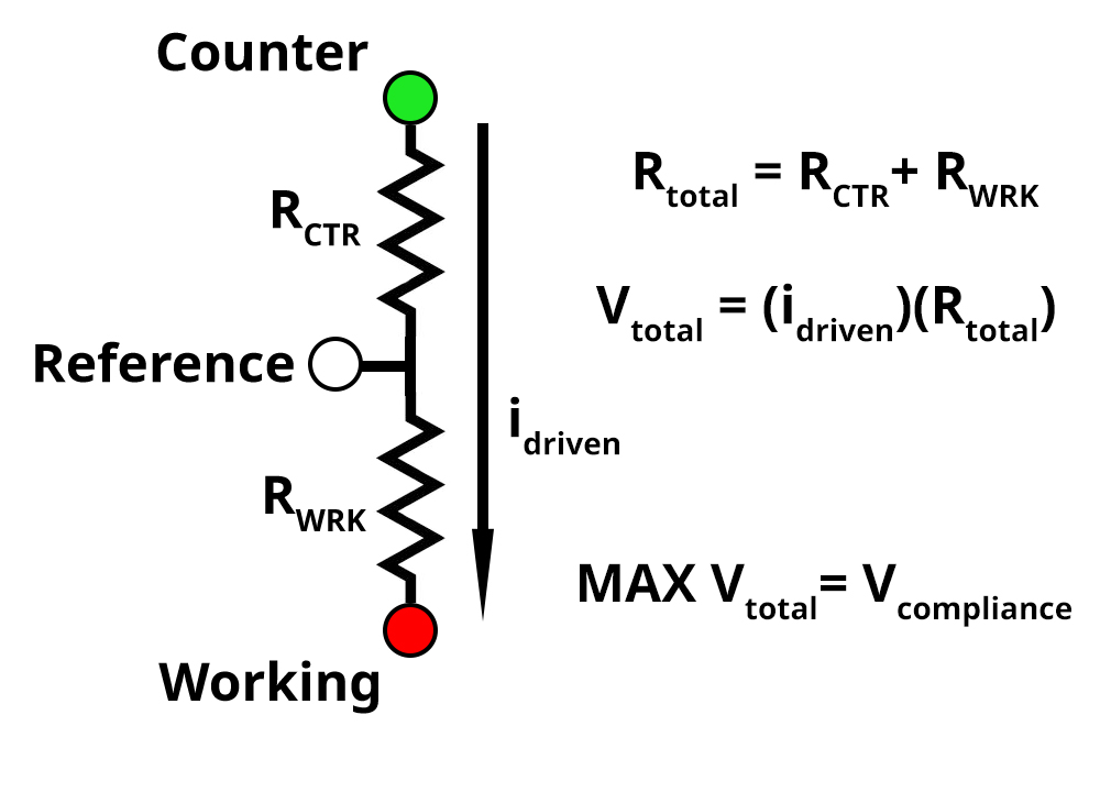 The green, white, and red circles represent the counter, reference, and working electrode leads on our potentiostat respectively. RCTR represents resistive elements between the counter and reference electrode, and RWRK represents resistive elements between the working and reference electrode. The resistive elements can vary depending on your electrochemical system. For example, in solution phase electrochemistry, the RWRK consists of the double layer capacitance, charge transfer resistance, and uncompensated solution resistance. If your solution is highly resistive, the potentiostat must apply a higher voltage to create the desired potential difference between the working and reference electrode.
If RWRK is 1 kΩ, applying 1 V between the working and reference electrode would result in a measured current of 1 mA based on Ohm’s law. This is equivalent to performing a bulk electrolysis experiment by applying 1 V and measuring 1 mA. If RCTR is 1kΩ, there is now two 1 kΩ resistors in series between the counter and the working electrode. To achieve the measured current of 1 mA, the voltage between the counter and working electrode must be 2 V. An additional 1 V is needed to meet the measured result of 1 mA. The maximum voltage (MAX Vtotal) a potentiostat can supply to meet the desired potential and current response is the compliance voltage. For you physics and circuit buffs out there, the diagram above should look a lot like a voltage divider….because it is.
Now that you have a better understanding of cell compliance, what is the minimum compliance voltage your electrochemical system needs? Well…it’s difficult to say, only Michael Faraday really knows. An electrochemical system may suddenly require double the compliance voltage if the measured current suddenly doubles. Thinking back to our diagram, if the measured current doubles, then the voltage Vtotal also doubles. This also applies to an increase in the resistance (RCTR). It’s not uncommon that the addition of a membrane or fritted tube to separate the counter and working electrode results in a compliance voltage issue for an otherwise normal electrochemical system.
We recommend that your potentiostat has a larger compliance voltage than your present research requires. For example, your future research may involve scaling up a reaction (requiring more current) or adding a membrane in-between your working and counter electrode. Specifically, we recommend you double or quadruple the intended voltage range you plan to operate in. For example, if you plan on working in aqueous solutions with a +1 to -1 V range (a span of 2 V), your potentiostat should have a compliance voltage of 4 to 8 V.
For energy storage devices such as batteries, compliance voltage is less of an issue because you are working in a two-electrode configuration. In a two-electrode configuration, the counter and reference electrode are shorted, which bypasses RCTR from the diagram above. If your research involves a two electrode configuration, the applied and measured voltage range of the potentiostat will be roughly equal to the minimum requirement in compliance voltage.
The Electrometer
On a potentiostat specifications page, there is a section titled “Electrometer.” The electrometer is part of the complex feedback loop in all potentiostats, but simply put, the electrometer measures the voltage between the reference and working electrode. A common specification on the electrometer section is the “input impedance,” which is a number like 1012 to 1014 Ω. The input impedance is the internal resistance of the electrometer, effectively allowing near “zero” current to flow through the electrometer. This is important as current that flows through the reference electrode can change its composition, thereby compromising its value and stability. In reality, there is a tiny bit of current that passes through the input impedance, called the “leakage current.” The leakage current is also a reported specification in the electrometer section. The lower the leakage current, the better. Rumor has it, Michael Faraday had a potentiostat with “actual” zero leakage current.
Additionally, the input impedance should be significantly higher than the resistance between the working and reference electrode. When working in aqueous and non-aqueous solvents the resistance values can range from 1 Ω to 103 Ω. If the input impedance is 1012 Ω, you will have no issues measuring the potential in your system. In general, the higher the input impedance, the more accurate your potential measurements will be.
In addition to the electrometer input impedance, potentiostat vendors will also report the input capacitance and the electrometer bandwidth. The bandwidth will limit the maximum frequency you can apply and measure for both current and voltage signals. The input capacitance is the capacitive element of the input impedance and is important for high-frequency measurements. Ideally, you want a large bandwidth and a low capacitance. If you are performing EIS, the electrometer specifications are an important consideration. However, the potentiostat accuracy contour plot (ACP) is the best way to determine if a potentiostat is appropriate for your EIS experiments. We’ll discuss the ACP in more detail later.
Another typical specification listed in the electrometer section is the CMRR, which stands for the common mode rejection ratio. To cut to the chase, you don’t need to worry about the CMRR. Most potentiostat companies have very similar, if not the same, specifications for the CMRR. However, if you are curious about what the CMRR is, continue reading. If not, skip to the next section on ADC and DAC.
Oh you’re still here? Great! As the name implies, the CMRR is a ratio that reflects how well the electrometer rejects signal with the same frequency, amplitude, and phase. The differential amplifier in a potentiostat takes the difference between two input signals and amplifies it. Perhaps you’ve seen the equation for an operational amplifier
 |
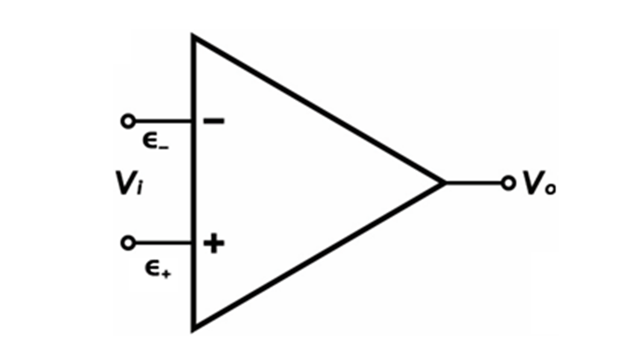
Simple operational-amplifier diagram
Where Vi is the input voltage, A is the gain, ε– is the non-inverting input, ε + is the inverting input, and Vo is the output voltage. In a perfect world, electronic signal with the same frequency, amplitude, and phase that enters the two input terminals (ε – and ε +) is rejected by the amplifier (Vo is zero). But we don’t live in a perfect world now do we? Experiments fail, reviewer 3 wants to reject your manuscript, and differential amplifiers don’t perfectly reject signal with the same frequency, amplitude, and phase. What this means is that outside electronic signals (electronic noise) can be amplified and show up in your experiments. The specifications listed on the CMRR is a measure of how well the amplifier can reject common-mode noise.
The ability to reject common-mode noise is a function of frequency. Potentiostat vendors will list several frequencies with a corresponding ratio in units of decibels. A decibel describes a unit of proportion by a power of 10. For example, 20 dB is a 100:1 ratio, while 80 dB is 100,000,000:1. A listed CMRR of 60 dB at 100 kHz means that two identical 100 kHz signals which enter both input terminals (same amplitude and phase) are attenuated by a factor of 1,000,000. In general, it’s harder for the electrometer to reject noise at higher frequencies. As a rule of thumb, the higher the CMRR, the better.
ADC and DAC: Another three-letter acronym on your spec sheet
Analog to digital and digital to analog converters (ACD and DAC, respectively) are necessary for all potentiostats that interface with a computer. At one point in time, potentiostats were controlled with buttons and knobs, and data were recorded on paper using a chart recorder. Crazy right? But most modern potentiostats require a computer to control the instrument and record data. On a specifications table, ADC and DAC are characterized by the number of bits and the sampling rate. A larger number of bits means higher resolution on the current and potential range. A higher sample rate yields better time resolution or higher frequency limit of measurements. You might think that the higher the bit count the better? But sometimes there is a tradeoff between the current or voltage resolution vs. the sampling rate. A 24-bit ADC and DAC can have a 100 – 400 kHz sampling rate. While a 16-bit ADC and DAC can have a 1 – 10 MHz sampling rate. Modern potentiostats typically have a 16-bit ADC and DAC, and that is sufficient for most electrochemistry experiments. 24-bit ADC and DAC’s tend to be more expensive and require additional circuitry for potentiostat operation than a 16-bit ADC and DAC. The additional cost of the component plus added circuitry gets passed on to you when purchasing the potentiostat. Additionally, if you are looking for higher resolution, a potentiostat with a lower-bit ADC and DAC should also have several current and voltage ranges you can adjust depending on the experiment. This way you can achieve high current or voltage resolution without a high bit ADC and DAC. If a potentiostat company doesn’t give ADC bit counts, they might convey the same information through the current and potential resolution or smallest current and potential steps possible. For more information about ADC’s and DAC’s, check out our knowledgebase article on the Electrode Range.
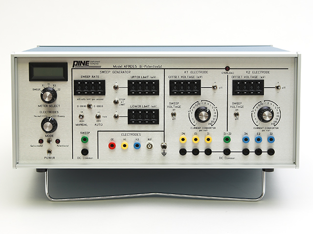
You would need to hook this up to a charter recorder to collect data. Thankfully modern potentiostats hook up to computers for data collection!
Do I need Electrochemical Impedance Spectroscopy (EIS)?
If you have a traditional chemistry background, EIS (one of the AC techniques) might not have been part of your formal training. Perhaps DC voltammetry techniques such as cyclic voltammetry were sufficient for your research. Michael Faraday didn’t use EIS, why should I? You might ask yourself if techniques like EIS add value to your research, or is it unnecessary and just adds cost to your potentiostat? Over the last few years, more and more reviewers of electrochemistry publications require EIS data, regardless of whether it is appropriate to the paper. EIS is traditionally used by battery, corrosion, and fuel cell researchers, but is now increasingly applied to many other electrochemical experiments. Specifically, EIS is valuable because it allows you to model your chemical system as an equivalent circuit. In batteries, corrosion, and fuel cells, these circuit diagrams can be extremely complex, making circuit fitting software very helpful. If you are performing electrochemistry on a redox-active molecule in a liquid electrolyte, your system is generally modeled by a Randles-equivalent circuit. Information such as the charge transfer resistance, double-layer capacitance, and the uncompensated solution resistance can be determined using EIS between 100 kHz to 10 μHz. Higher frequencies beyond 1 MHz are mostly useful for studying solid state devices. However, for ordinary electrochemical systems, such as solution phase redox processes, one rarely needs frequencies above 1 MHz and 100 kHz is the upper limit for some battery reactions. Potentiostat prices can increase when adding EIS. The price increases even more when the potentiostat is capable of higher frequencies.
The Accuracy Contour Plot (ACP), and how to read it
If you’ve decided that your potentiostat needs EIS, then you should look at the ACP of the potentiostat. However, unless you are a potentiostat manufacturer, then you’ve probably never had to read an ACP. So what is an ACP? In short, an ACP is a visual representation of the potentiostat’s impedance and frequency limitations. Below is the ACP for the WaveDriver 100 potentiostat and WaveDriver 200 bipotentiostat.

In an ACP, the y-axis shows the measured impedance, the x-axis shows the applied frequency of the EIS signal, and both axes are plotted using a logarithmic scale. This is also the same plotting convention as what is used on half of a Bode Plot (the secondary y-axis on a Bode Plot shows phase angle). Parts of the ACP are shaded differently to represent the measurement accuracy at an impedance and frequency value.
The accuracy is reported as being within a certain percentage of the real impedance value and within a certain degree of the phase angle. For example, according to the ACP above, if you were to perform EIS on a 10 kΩ resistor, the impedance you collected at 100 Hz would be within 1% of the actual value. Additionally, the phase angle of the resistor would be within 1° of the real value (which in the case of a pure resistor is 0°). However, if you measure a 10 MΩ resistor at 100 kHz (which is in the yellow shaded region), the measured impedance would only be accurate within 5% of the actual value, and the phase angle would only be within 5° of the actual value. If you perform an experiment whose frequency and/or impedance fall outside the range of the ACP, measurement accuracy may be severely compromised. This is one reason researchers sometimes can be fooled into thinking their potentiostat is performing poorly when, in reality, their experimental demands are beyond the instrument’s AC capability. It is essential to understand where your EIS experiment lies in the spectrum of an instrument’s ACP to determine if the results should be considered accurate or not.
All that being said, the ACP should be taken with a grain of salt. No information within an ACP mentions how the measurements were taken. It can be assumed that the data used to construct an ACP was collected under ideal conditions, with very low noise, and correct cable orientation. Let’s recall the first thing when it comes to choosing a potentiostat. Your instrument should be able to perform the experiments that you are interested in. The ACP represents the fundamental limitations of the potentiostat’s EIS capabilities. You should consult the potentiostat vendor if you think the EIS experiment you are trying to perform is at the edge of, or beyond the published ACP limits. For more on ACPs, check out our knowledgebase article.
Software and Support
Perhaps you’ve found multiple potentiostats from different vendors that all do exactly what you need, and they are all about the same price. Then what? How do you choose from that point? The next thing to consider when purchasing a potentiostat is the software and user experience. Is the software easy to use? What kind of functionality does it offer? Do you need multiple licenses? Is the software glitchy and does it run the risk of crashing? You should ask for a trial or free version of the software. A trial version should give you a good sense of how easy it is to import and export data or understand how data files are structured. Some software comes with analytical tools such as peak position, area calculator, baseline correction, and more. If you are doing EIS, does the software come with EIS fitting and simulating software?
What about the technical support provided by the potentiostat vendor? When a problem occurs (and it will, this is research we’re talking about!), how quickly and efficiently does the vendor communicate and provide support to you? In addition to the communication and support speed, are the technical support staff helpful, easy to work with, and engaging? As strange as it sounds, quite often the Pine Research technical support staff get technical questions on other vendor’s potentiostats because they don’t provide sufficient technical support themselves.
Final verdict
There are a lot of considerations when purchasing a potentiostat. First and foremost, the potentiostat should perform the experiments you are interested in. Once you’ve confirmed that the potentiostat can do the job, determine if the software is easy to use. But to be absolutely sure you’re making the right decision, most potentiostat vendors have demo units you can test out. Once you’ve done some research about which potentiostat you are interested in, ask the vendor for a demo unit. Typically, they can ship a potentiostat to you to test out for three weeks to a month. But be careful! Sometimes the first potentiostat you demo becomes the basis for comparing other potentiostats. This can lead to unintended bias. Make sure you take an objective look at how the potentiostat functions and your overall experience using it. May Michael Faraday smile upon your experiments and provide you with the wisdom you seek in choosing your potentiostat.
References
1. Bard, A.J.; Faulkner, L. A. Electrochemical Methods: Fundamentals and Applications, 2nd ed. Wiley-Interscience: New York, 2000.
2. Atkins, Peter (2010) Inorganic chemistry 5th edition. New York: W.H. Freeman and Company, New York
3. C. Chakkaravarthy, A.K. Abdul Waheed, H.V.K. Udupa, Journal of Power Sources, Volume 6, Issue 3, 1981, 203-228
4. Geoffrey J. May, Alistair Davidson, Moris Monahov, Journal of Energy Storage, Volume 15, 2018, 145-157
5. Ma, R., Lin, G., Zhou, Y. et al, A review of oxygen reduction mechanisms for metal-free carbon-based electrocatalysts. npj Comput Mater, 5, 78 (2019)
6. A. Kirubakaran, Shailendra Jain, R.K. Nema, A review on Fuel Cell Technologies and power electronic interface, Reviewable and sustainable Energy Reviews, 13, 9, 2009, 2430-2440

Comments: